

EdilKamin H2 Oceano 15, H2 Oceano 23, H2 Oceano 28 Installation, Use And Maintenance Manual
H
OCEANO 15-23-28
2
I Installazione, uso e manutenzione pag. 2
UK Installation, use and maintenance pag. 20
F Installation, usage et maintenance pag. 38
E Instalación, uso y mantenimiento pag. 56
D Installations-, Betriebs- und Wartungsanleitung pag. 74
NL Installatie, gebruik en onderhoud pag. 92
SL Vgradnja, uporaba in vzdrževanje str . 110
- 1 -

Dear Sir/Madam
Congratulations and thank you for choosing our product.
Please read this document carefully before you use this product in order to obtain the best performance in complete safety.
For further details or assistance, please contact the DEALER where you purchased the product or visit our website
www.edilkamin.com. and click on DEALERS.
Please note that a quali¿ ed dealer MUST install the ¿ replace as is stipulated in the Italian Ministerial Decree No. 37 ex Italian
Law No. 46/90.
For installations implemented outside Italy, please refer to the local regulations in the country of use.
ENGLISH
NOTE
- After having unpacked the boiler-¿ replace, ensure that its contents are complete and intact (“cold hand” handle, guarantee
booklet, glove, technical data sheet/CD).
In case of anomalies please contact the dealer where you purchased the product immediately.
You will need to present a copy of the warranty booklet and valid proof of purchase.
- Commissioning/ testing
Commissioning and testing must be performed by the DEALER. Failure to do so will void the warranty.
Commissioning, as speci¿ ed in standard UNI 10683 Rev. 2005 (section “3.21”) consists in a series inspections to be
performed with the boiler-¿ replace installed in order to ascertain the correct operation of the system and its compliance to
applicable regulations.
- Incorrect installation, incorrect maintenance, or improper use of the product, shall relieve the manufacturer from any damage
resulting from the use of this product.
- the proof of purchase tag, necessary for identifying the boiler-¿ replace, is located:
- on the top of the package
- in the warranty booklet found inside the ¿ rebox
- on the nameplate af¿ xed on the right side of the device;
This documentation must be saved for identi¿ cation together with the valid proof of purchase receipt. The data contained
therein must be reported when requesting information and made available should servicing be required;
- All images are for illustration purposes only; actual products may vary.
The undersigned EDILKAMIN S.p.a. with head of¿ ce headquarters at Via Vincenzo Monti 47 - 20122 Milano - Italy - VAT 0192220192
Declares under its own responsability as follows:
The wood Thermo Fireplaces illustrated below conforms to Regulation EU 305/2011 (CPR) and to the harmonised European
Standard EN 13229:2001 - A1:2003 - A2:2004 - AC:2006 - AC:2007
THE WOOD THERMO FIREPLACES, trademark EDILKAMIN, called H
2OCEANO 15-23-28
YEAR OF MANUFACTURE: Ref. Data nameplate Declaration of performance (DoP - EK 078-079-080) Ref. Data nameplate
EDILKAMIN S.p.a. will decline all responsability of malfunctioning or damage to the equipment in case of unauthorized substitution, assembly or modi¿ cations of any sort on the said equipment on the part of non-EDILKAMIN personnel.
- 20 -
TECHNICALAND HEATING SPECIFICATIONS
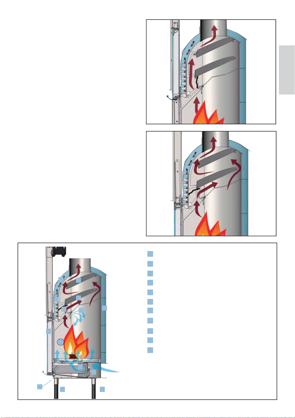
When turning on with the frame open, to facilitate combustion
start-up, the smoke damper (
) remains in the opening position
so that smoke can directly and easily reach the chimney ŏ ue.
When combustion has been started up, the smoke damper
also closes automatically when the door is closed (
- Ŏ g. b
In this mode, before reaching the chimney ŏ ue, the smoke
deviates in such a way to lap and give off heat to the water in
an efŎ cient manner.
The by-pass is automatically controlled by the door’s movement.
H2OCEANO is designed to heat water by the combustion of
wood in the hearth.
The water contained in the thermo Ŏ replace is heated and sent
into the heating system (radiators, heated towel rails, underŏ o-
or heating panels) and also heats the room in which it is located
via natural convection radiation.
The thermo Ŏ replace MUST NEVER FUNCTION WITHOUT
WATER IN THE SYSTEM.
The water heats up, circulating in the cavity that runs around
the entire semi-circular wall and dome of the hearth.
The hollow space is constructed in thick steel sheet.
The hearth is closed in the front by a door that slides up and
down and side to side for cleaning the glass.
INNOVATIVE PATENTED ASH GRILLE
This allows for the distribution of primary combustion air not
only from the bottom up, but also horizontally to achieve high
oxygenation of the ŏ ame, better combustion and increased power.
“GASKET-SAVING” DOOR
During sliding, the door remains slightly ajar from thermo Ŏ re-
place inlet in order to protect the gaskets. In the closed position
the door is perfectly ŏ anked against the thermo Ŏ replace to en-
sure maximum sealing and therefore optimal performance. The
handle is removable or it can be Ŏ xed to the door (see pg. 29)
(a)
(b)
s
ENGLISH
AUTOMATIC SMOKE BY-PASS
When turning on with the frame open, to facilitate combustion
start-up, the smoke damper (SS
so that smoke can directly and easily reach the chimney ŏ ue.
When combustion has been started up, the smoke damper
also closes automatically when the door is closed (SS
In this mode, before reaching the chimney ŏ ue, the smoke
deviates in such a way to lap and give off heat to the water in
an efŎ cient manner.
The by-pass is automatically controlled by the door’s movement.
) remains in the opening position
- Ŏ g. b))..
H
I
S
A
A
C
H
s
Deŏ ectors/Ceilings
A
Grill motor housing
B
Post-Combustion
C
Automatic external air inlet adjustment valve (optional)
D
Possibility of applying adjustable feet (optional)
E
Calibration for automatic adjustment of combustion air
F
G
Up/down sliding door
H
Enveloping cavity for water containment
Safety coil for thermal relief (CS version)
G
B
L
D
F
E
E
I
L
Primary combustion air distribution ash grille
Smoke diversion damper
S
- 21 -
SAFETY INFORMATION
IMPORTANT: ONLY THERMO FIREPLACES WITH
COILS DRIVEN BY A THERMAL RELIEF VALVE
SHOULD BE INSTALLED ON CLOSED TANK SY-
STEMS (version marked with the abbreviation CS).
• The installer is responsible for the correct installation of the
system, which is to be compliant with UNI standards 10683 –
ENGLISH
9615/90 – 10412:2
• All must be performed by qualiŎ ed personnel according to
Ministerial Decree 37 ex Law 46/90
H2OCEANO MUST NEVER BE MADE TO OPERATE WITHOUT WATER IN THE SYSTEM.
MUST BE MADE WITH A PRESSURE OF ABOUT 1.5 BAR.
IT CAN BE DAMAGED IF IT IS IGNITED WITH NO WATER IN THE SYSTEM.
• The thermo Ŏ replace is designed to heat water by means of
wood combustion in the hearth.
• The only hazards that can derive from using the thermo Ŏ re-
place pertain to non-compliance with the installation instructions, direct contact with live electrical parts (inside), contact
made with the Ŏ re and hot parts or foreign substances being put
in the Ŏ replace.
• For the thermo Ŏ replace to function properly installation
must be carried out according to the instructions given in this
booklet and the door must only be opened to reŎ ll the hearth
with wood.
• Never put foreign substances in the hearth.
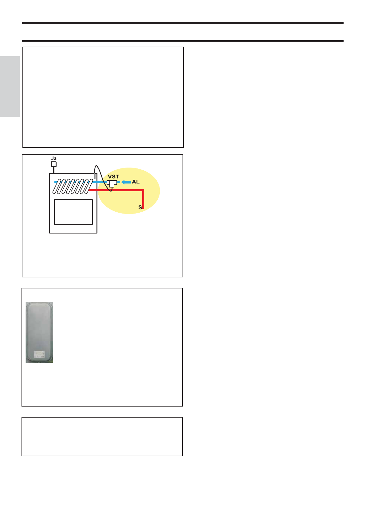
The thermal relief valve (TRV - provided by Edilkamin) must
be connected to the cooling circuit (AL) with a minimum
pressure of 1.5 bar.
JA = automatic relief valve
S = drain
Litres ?
• The heating system must include an expansion tank dedicated
only to the thermo Ŏ replace, evaluated based on the volume of
water present in the system itself (an expansion tank shared with
other generators is not allowed).
• Whilst functioning, the door must never be opened. In fact,
combustion is fully automatic and requires no manual interven-
tion.
• Do not use ŏ ammable products to clean the smoke channel
(the ŏ ue section connecting the boiler-Ŏ replace smoke outlet to
the chimney ŏ ue).
• The glass can be cleaned when COLD with a suitable product
(e.g. GlassKamin) and a cloth. Do not clean when hot.
• The exhaust pipes and the door become very hot when the
thermo Ŏ replace is used.
• Do not place anything that is not heat resistant close to the
thermo Ŏ replace.
• NEVER use liquid fuel to ignite the thermo Ŏ replace or to
rekindle the embers.
• Do not obstruct the external air inlets in the room where the
Ŏ replace is installed or the air inlets of the thermo Ŏ replace
itself.
• Do not wet the thermo Ŏ replace and do not go near the elec-
trical parts of the system with wet hands.
1 Year
• The safety and thermal relief valves must be checked at least
once a year by qualiŎ ed personnel according to Ministerial De-
cree 37 ex Law 46/90.
• Do not use reducers on the smoke exhaust pipes.
• The thermo Ŏ replace must be installed in a place that is sui-
table against Ŏ re hazards and equipped with all that is required
(power and air inlets/outlets) for it to function properly and
safely.
- 22 -

GENERAL SAFETY REGULATIONS
IN CASE OF INSTALLATION ON OPEN
TANK SYSTEMS
The connections, commissioning and veriŎ cation of proper
operation of the thermo Ŏ replace must be carried out by quali-
Ŏ ed personnel, who can implement all connections in accordance with the laws in force, particularly with Italian D.M 37
Law No. 46/90, apart from complying with these instructions.
For installations implemented outside Italy, please refer to the
local regulations in the country of use.
The thermo Ŏ replace and the system are Ŏ lled with water that
ŏ ows from the water inlet pipe (the diameter must not be less
than 18 mm) to the open expansion tank.
All the vents of the radiators must be opened during this
phase so as to prevent air pockets from forming in the system,
which would obstruct the circulation of water.
NB:
• The open tank should be positioned at a height greater than
3 m higher than the highest component of the primary circuit
and less than 15 m from the edge of the thermo Ŏ replace.
IN CASE OF INSTALLATION ON CLOSED
TANK SYSTEMS
(provisions in addition to those provided for open tank
systems)
• Be careful not to exceed 1.5 bar when Ŏ lling the system.
• Only if a thermal relief valve actuates the coil can the
Ŏ replace be installed on a CLOSED TANK system (version
marked with the abbreviation CS).
• When connecting a thermo Ŏ replace to an existing system,
an assessment must be made regarding a need for another
CLOSED TANK on the system.
- The upstream pressure of the cooling circuit must be at least
1.5 bar (UNI 10412/2 point 6.2).
ENGLISH
• In any case, the tank must be high enough to create a greater
pressure than that produced by the pump (circulator).
• The system must never be Ŏ lled directly from the water
mains as the pressure may be greater than that stipulated on
the data plate of the thermo Ŏ replace, with resulting damage
to the thermo Ŏ replace itself.
• The safety pipe to the expansion tank must allow the water
to ŏ ow freely without shut-off valves and be appropriately
insulated to prevent the water inside from freezing, which
would compromise the connection.
• The water inlet pipe must not have taps nor curves.
• The maximum operating pressure must not exceed 1.5 bar
• The testing pressure is 3 bar.
• It is a good idea to add an anti-freeze liquid to the water
contained in the system or to observe standard UNI 8065.
• Never ignite the Ŏ re in the thermo Ŏ replace (not even as a
test) unless the system is Ŏ lled with water as this could cause
irreparable damage.
• Connect the drains of the thermal relief valve (TRV) and
the safety valve (SV) (diagrams are found on the following
pages).
• The ŏ ow test of the system must be carried out with the
expansion tank open.
• It is recommended to install a 6 bar safety valve on the hot
sanitary water circuit so as to drain any excessive increase in
the volume of the water in the heat exchanger.
• Place all the components of the system (circulator, heat
exchanger, valves, etc.) in easily accessible points for routine
and special maintenance procedures.
WATER TREATMENT
If need be, antifreeze, descaling and anticorrosive solutions
are to be added to the water.
A softener must be used if the hardness of the water used to
reŎ ll and top-up the system exceeds 35°f (French degrees).
Please refer to UNI 8065-1989 standard (water treatment in
domestic heating systems).
- 23 -
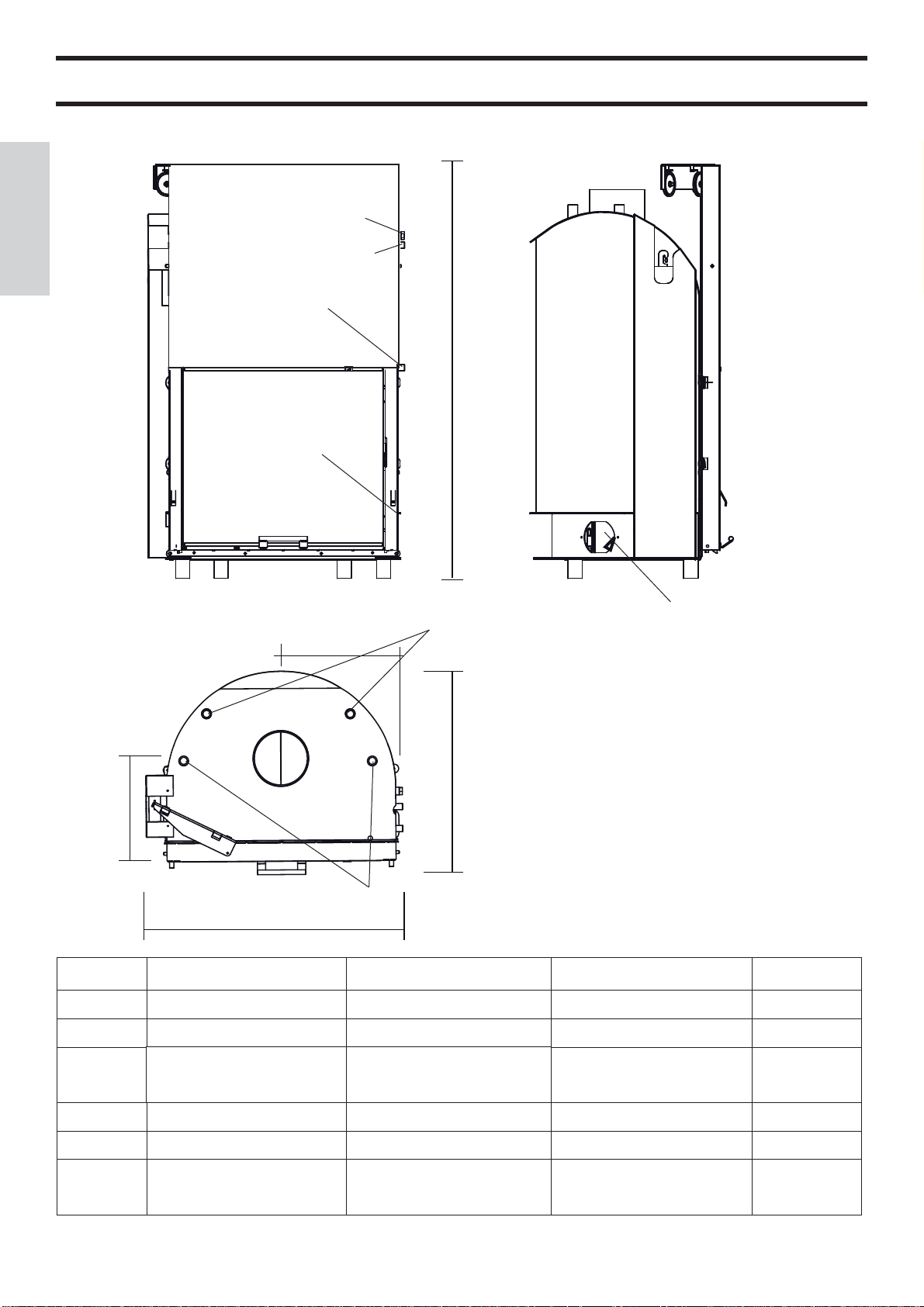
DIMENSIONS
FRONT SIDE
well for probe
ENGLISH
SYSTEM
thermal relief coil ŏ ow 1/2” M
(closed tank version)
thermal relief coil return 1/2” M
(closed tank version)
H
drain
combustion air
water return to system 1” M
X
P
Y
water ŏ ow to system 1” M
L
H2OCEANO 15 - 15/CS H2OCEANO 23 - 23/CS H2OCEANO 28 - 28/CS
L 74 88 106 cm
P62 68 83cm
H
X34 34 51cm
Y36 37 50cm
internal
hearth
dimensions
135 without feet
(with feet + 14 cm)
50x38 60x50 78x60 cm
147 without feet
(with feet + 14 cm)
147 without feet
(with feet + 14 cm)
cm
THE INLET AND OUTLET PIPES MUST BE CROSSED FOR THIS TO FUNCTION PROPERLY
- 24 -

TECHNICALAND HEATING SPECIFICATIONS
15-15/CS 23-23/CS 28-28/CS
Thermal output (burnt) 18,5 27,8 34,8 kW
Rated power 14,8 22,2 27,8 kW
Water heating power 12,1 18,2 22,8 kW
Approx. overall efŎ ciency 80 80 80 %
Approx. water efŎ ciency 82 82 82 %
Class efŎ ciency (EN 303-5) > 3 > 3 > 3 -
ø female smoke outlet 18 22 25 cm
Maximum operating pressure 1,5 1,5 1,5 bar
Fuel consumption 4,5 7 8,5 kg/h
Water capacity 50 100 130 litres
Heating capacity * 355 535 670 m³
Weight including packing 240 285 325 kg
Hot sanitary water production (kit 1- 3 - N3 - N3bis)** 13-14 13-14 13-14 litres/min
ø external air inlet 12,5 12,5 12,5 cm
ENGLISH
System return (male) 1” 1” 1” inches
System ŏ ow (male) 1” 1” 1” inches
N.B.: DATA PROJECT (Refer to standard EN 13229)
* The heatable room dimensions are calculated on the basis home insulation in compliance with Italian law 10/91, and subsequent
changes together with an expected heat output of 33 Kcal/m³ per hour.
* It is also important to consider the position of the boiler-Ŏ replace in the room to be heated.
* * boiler temperature is 70° - (ðT=25K)
THE DIAMETER OF THE CHIMNEY FLUE TO BE USED MUST BE ASSESSED BY THE INSTALLER ACCORDING TO THE HEIGHT OF THE CHIMNEY FLUE ITSELF.
THE INLET AND OUTLET PIPES MUST BE CROSSED FOR THIS TO FUNCTION PROPERLY
The data shown above is purely indicative.
EDILKAMIN s.p.a. reserves the right to change the products at its discretion without notice.
- 25 -
INSTALLATION
NO
IMPORTANT ADVICE REGARDING THE
INSTALLATION
Other than that described in this documentation, you are also
asked to note the following UNI standards:
- No. 10683 - Ŏ rewood heat generators:
installation requirements
- No. 9615/90 - calculating the internal dimensions of Ŏ replaces
- No. 10412:2 - hot water heating systems.
ENGLISH
SpeciŎ c safety requirements for systems provi
ded with residential solid fuel burning applian
ces and combined boiler, not exceeding a total
nominal heat input of 35 kW.
Particularly:
- Before carrying out any assembly it is important to verify
compatibility of the appliance, as stipulated in UNI 10683
standard, paragraphs 4.1 / 4.1.1 / 4.1.2.
- When assembly is completed, the installer must implement
“start-up operations” and issue documentation as required
by UNI 10683 standard in paragraphs 4.6 and 5, respectively.
- The connections, commissioning and veriŎ cation of pro-
per operation of the thermo Ŏ replace must be carried out
by qualiŎ ed personnel, who can implement the electrical and
plumbing connections as required by UNI standards 10683,
paragraph 4.5 and 10412:2, apart from complying with these
assembly instructions.
- VeriŎ cation must be carried out with the Ŏ replace on and
after having been on for a couple of hours, before covering the
thermo Ŏ replace, so that you can intervene if need be.
After which, the Ŏ nishing operations such as:
- setting-up the Ŏ replace mantel
- mounting the Ŏ replace covering
- pilasters, painting, etc.
are carried out, once the tests are completed successfully.
Consequently, EDILKAMIN does not accept responsibility for
expenses deriving from demolition as well as construction even
if either occurs as a result, after having replaced any damaged
parts of the thermo Ŏ replace.
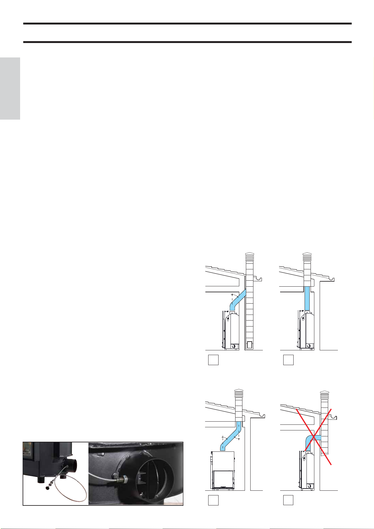
CHIMNEY FLUES AND CHIMNEYPOT
The thermo Ŏ replace smoke outlet has a circular crosssection
so that stainless steel pipes can be used. If the chimney ŏ ue
inlet is not vertically above the thermo Ŏ replace, the connection
from the Ŏ replace to the ŏ ue must not have a narrowing
section or inclinations greater than 45° (Ŏ g. 1-2-3-4).
If the chimney ŏ ue is not brand new or too big, it is recommen-
ded to Ŏ t in stainless tubes of an appropriate diameter and with
suitable insulation.
If the chimney ŏ ue is installed outside, it is recommended to
use an insulated, double walled, stainless steel ŏ ue.
The characteristics of the construction must be suitable to
withstand a smoke temperature of at least 450° C, with particular reference to the mechanical resistance, insulation and the
gas tight sealing.
The junction of the steel ŏ ue inlet and the smoke outlet of the
Ŏ replace must be sealed with high temperature mastic.
The fundamental characteristics of the chimneypot are:
- an internal cross-section at the base, which is the same as that
of the chimney ŏ ue.
- an outlet cross-section which is no smaller than twice that of
the chimney ŏ ue.
- its position must be high enough to catch the wind and avoid
downdraft areas in turbulent wind.
In addition to that mentioned above, please consider the
indications stipulated in UNI 10683/2005 standard, paragraph 4.2: “connection to the smoke outlet system” and its
subsections.
max.45°
EXTERNAL AIR INLET
An external connection with a 12,5 cm diameter crosssection throughout (refer to the technical table) is absolutely
necessary for the thermo Ŏ replace to function properly and
is therefore imperative for this to be implemented.
This connection must link the air adjustment mechanism (E),
delivered separately. The mechanism, delivered separately,
can be assembled either right or left of the thermo Ŏ repla-
ce. Connection can be made with a ŏ exible aluminium pipe.
Ensure that the points where there may be dispersion of air are
sealed well. The air adjustment mechanism (E) can be removed and mounted on the right side of the thermo Ŏ replace. It is
recommended to place a protection grille on the outer part of
the air inlet channel, however, ensure that this does not reduce
the cross-section. For distances longer than 3 m or with bends,
increase the given cross-section by a minimum of 10% to a maximum of 20%. The intake of external air must enter at ŏ oor
level (it cannot enter from above).
E
E
- 26 -
3
1
45°
45°
2
4

INSTALLATION
If combining with a pre-fabricated Edilkamin covering, to deŎ -
ne the exact positioning of the thermo Ŏ replace, it is important
to take the chosen covering model into consideration.
The positioning is implemented according to the model chosen
(refer to the installation instructions found inside the packaging
of each thermo Ŏ replace covering).
Always ensure the thermo Ŏ replace is level during the installa-
tion process.
- Drill a hole into the wall or the ŏ ooring for the external air
intake and connect the air adjustment mechanism to the hole as
described in the chapter called “external air inlet”.
- Use a stainless steel ŏ ue to connect the thermo Ŏ replace to the
chimney ŏ ue, adhering with the diameters indicated in the spe-
ciŎ cations table and the guidelines given in the chapter called
“chimney ŏ ues”.
- Verify that all moving parts function properly before setting
the thermo Ŏ replace covering in place.
- This system must be tested and ignited for the Ŏ rst time
before the covering is set in place.
INSTALLATION COVERING, FIREPLACE MANTEL AND VENTILATION OUTLETS
The base of the thermo Ŏ replace covering must allow the
internal air to be recycled. Therefore, suitable slots or apertures
must be made for the air to pass through. Parts of the thermo
Ŏ replace covering that are made of marble, stone and bricks
must be mounted with a small gap between them and the Ŏ re-
place so as to prevent possible breakage due to expansion and
excessive overheating.
Wooden parts must be protected by Ŏ re resistant panels and
no part must touch the thermo Ŏ replace, on the contrary, there
must be an appropriate distance of at least 1 cm to allow the
air to ŏ ow, preventing heat accumulation. The Ŏ replace mantel
can be made of Ŏ reproof plasterboard panels or gypsum board
and, however, of completely Ŏ reproof material. Air should be
allowed to ŏ ow inside the Ŏ replace mantel (through the gap
between the door and the beam). Through convective motion,
the air will ŏ ow out from the grille installed at the top, resulting
in heat recovery and preventing excessive overheating.
The Ŏ replace mantel must have appropriate openings to carry
out maintenance on the Ŏ ttings.
In addition to that mentioned above, please consider the indications stipulated in the UNI 10683 standard, paragraphs
4.4 and 4.7: “insulation, Ŏ nishing, Ŏ replace covering and
safety recommendations”.
Insulating mats must be applied when using an installation
KIT so as to protect it from the heat radiation emitted by
the thermo Ŏ replace.
INLET FRAME (OPTIONAL)
To facilitate coupling with the covering’s components, the thermo Ŏ replace can be Ŏ tted with a frame (A) to be applied on the
front of the inlet.
Plasterboard
A
ENGLISH
INSTRUCTIONS FOR USE
Practical advice
It is recommended to keep the radiators closed in the room
where the thermo Ŏ replace is installed; The heat emitted from
the outlet may be sufŎ cient to heat.
- An incomplete combustion process causes excessive fouling
on the heat exchanger pipe.
To prevent this you must:
- burn dry wood.
- ensure the hearth contains a bed of embers and burning carbon before adding more wood.
- place larger logs together with smaller ones.
- make sure the temperature of the return water is at least 50 °C
(use temperature control valve).
Igniting the Ŏ replace
- Ensure that at least one radiator is always open.
- Actuate the switches of the electronic regulator.
- Place a pile of medium-thin dry wood in the thermo Ŏ replace
and ignite the Ŏ re.
- Wait a few minutes until it reaches sufŎ cient combustion.
- Close the door
- Set the thermostat on the electronic regulator (*) at a temperature between 50 and 70° C.
NOTE: There may be a slight smell of paint the Ŏ rst few times
it is ignited, however, this will disappear quickly.
A
3-way valve
- During ignition the 3-way valve (*) diverts the ŏ ow of water,
forcing it to return directly to the thermo Ŏ replace;
when the set temperature is reached, the 3- way valve (*)
diverts the ŏ ow to the system (does not depend on the kit
installed).
By-pass damper
- When the door is closed, the by-pass damper automatically
diverts smoke, thus improving efŎ ciency.
- When the door is opened, the damper bypass opens automatically, allowing the smoke to reach the smoke ŏ ue directly,
preventing it from coming out of the inlet.
Thermal Relief Valve
If the water temperature exceeds 90° C (e.g. because of too
much wood being placed in the hearth) the thermal relief valve
will be activated and the acoustic signal triggered.
In this case you must proceed as follows:
Do not load additional fuel and wait for the temperature to fall
below 80°C checking the warning lights on the electronic regulator. The hot water tap can be opened to speed up the cooling
process if the thermo Ŏ replace is equipped with a hot sanitary
water production KIT.
(*) these components of the system are to be provided by the installer.
- 27 -

INSTRUCTIONS FOR USE
E
ENGLISH
Ŏ g. 1
External air regulation
The control, via the dedicated damper (E- Ŏ g. 1) located on the
external air intake, regulates the quantity of primary air necessary for combustion.
Push the knob to close the external air intake; pull the knob to
open the external air intake.
OPTIONAL THERMOSTATIC VALVE (FIG. 2)
Manual adjustment of combustion air (to be carried out
during installation)
To obtain the desired water temperature, manually calibrate the
thermostatic valve.
Using the Allen supplied (X - Ŏ g. 3) it is possible to regulate
the thermostatic valve using the screw located just below the
ash pan (Y - Ŏ g. 3).
• Screw on RT: combustion air on minimum
• Screw all the way to the LT: combustion air on maximum
• obviously, all intermediate settings are possible
NOTE: If a thermostatic valve must be installed, you must remove the manual air intake damper by removing the valve and
the cable with the knob (E- Ŏ g. 1).
Automatic adjustment of combustion air
The combustion air is captured by the external air intake via the
outlet (E - Ŏ g. 1) and reaches the hearth through the ash grille.
This is adjusted using valve V (Ŏ g. 2).
If the temperature inside the hearth is low,compared to that set
during calibration, the valve automatically positions itself in
the open position and vice versa, it closes when the temperature
is high.
This allows the right quantity of wood to be consumed for the
set thermal comfort to be reached and unnecessary waste is
avoided.
NOTE: when the thermostatic valve fully closes the combustion air inlet completely (the temperature in the hearth is very
high), limited but sufŎ cient access is allowed for the air to
enter and keep the glass clean.
Installation of thermostatic valve “V” is optional.
All operations must be performed with the thermo Ŏ re-
place off and fully cooled.
The mains power must also be disconnected.
Proceed as follows:
- Open the door and block it in the open position in order
to easily work inside the hearth (Ŏ g. 4).
- Remove the following components (Ŏ g. 5):
• ash pan
• cast iron grille
• hearth base
Note: The hearth base is only on rested on the gasket,
therefore to remove it simply lift it up (keep in mind that
if the thermo Ŏ replace has been used for a long period of
time there may be signiŎ cant adhesion between hearth
base and hearth).
- Install the pre-assembled thermostatic valve on the
Ŏ xing pate (Ŏ g. 6 - pg. 29).
- Secure the plate with the three screws supplied (S) to
the bottom of the hearth (Ŏ g. 7 - pg. 29).
Before Ŏ xing, make sure to pass the adjustment cable and
the probe wire through the prepared slots.
- The adjustment cable must be inserted into the front
hole under the ash pan (Ŏ g. 8 - pg. 29), and secured in
position using the elastic ring supplied.
- The probe wire must be unwound along the right side of
the ash pan proceeding then to the outside of the thermo
Ŏ replace (Ŏ g. 9 - pg. 29) via the hole on the right side.
- At this point insert the probe in the well on the thermo
Ŏ replace (pg. 24).
- Before putting back the hearth base check the wear condition of the gasket (if necessary replace it) and insert the
gasket on the perimeter of the Ŏ xing plate of the thermo-
static valve (Ŏ g. 8 - pg. 29).
Ŏ g. 2
Ŏ g. 3
V
Ŏ g. 4
Y
X
Ŏ g. 5
- 28 -

REAR VIEW
INSTRUCTIONS FOR USE
Probe positioning for OPEN TANK version
probe wire
ENGLISH
S
Ŏ g. 6
Ŏ g. 7
S
adjustment cable
S
adjustment cable
S
gasket
S
Ŏ g. 10
Probe positioning for CLOSED TANK version
First insert the probe for the temperature relief valve, then the
probe for the thermostatic valve.
S
Ŏ g. 12
Ŏ g. 11
Ŏ g. 13
Ŏ g. 8
Ŏ g. 9
adjustment cable
probe wire
probe wire
Ŏ g. 14
Ŏ g. 15
- 29 -

INSTRUCTIONS FOR USE
Door opening
- Use the provided removable handle to open the door (Ŏ g. 16).
- The same handle can be Ŏ xed to the door using the 2 grub
screws supplied.
ENGLISH
Ŏ g. 16
Installing counterbalances
The latch door is equipped with counterbalances which ensure
smooth movements as well as closure of the door.
The counterbalances can be regulated by adding platte/s
(additional counterbalances) that are supplied with the thermo
Ŏ replace (P - Ŏ g. 17).
P
Ŏ g. 17
MAINTENANCE
Cleaning the hearth
- The soot deposits that tend to accumulate on the internal walls
of the hearth decrease the efŎ ciency of heat transfer.
- It is therefore necessary to clean the Ŏ replace regularly, by
bringing the water temperature to 80 / 85° C to soften the fouling and then remove this with a steel spatula.
Glass cleaning
- Use an appropriate spray for ceramic glass to clean the glass
(Glasskamin - Edilakmin)..
- The glass must be cleaned when cold.
- For the opening swing of the door it is necessary to bring it in
the closed position.
- Insert the “cold handle” door handle on the latch between the
structure and the door and turn to open (Ŏ g. 18).
Ŏ g. 18
- 30 -

SYSTEM FOR AN OPEN TANK INSTALLATION
AN EXAMPLE OF A HYDRAULIC SYSTEM FOR A THERMO FIREPLACE WITH HOT SANITARY WATER PRODUCTION USING
Electricity
Mains
KIT 1
Safety pipe Ø> 28mm
Inlet pipe Ø> 18mm
Collector
ACS: Hot Sanitary Water
AF: Cold Water
EV: 3-way Solenoid Valve
F: Flow Switch
MI: System Flow
NA: Normally Open
NC: Normally Closed
P: Pump (circulator)
RA: Radiators
RE: Electronic Regulator
RI: System Return
S: Drain
Sc 20: 20-plate Heat Exchanger
ST: Temperature Sensor
TC: Thermo Fireplace
V: Valve
VE: Open Expansion Tank
VSP: 1.5 bar Pressurized Safety Valve
VST: Thermal Relief Valve
Ja: Automatic Relief Valve
Kit 1 is designed to facilitate the work carried out by the installers. In fact, it consists of all the necessary components for the
product to be properly installed.
NB: insulating mats must be applied so that the components of the kit are well-protected from the heat radiation emitted
by the thermo-Ŏ replace.
1. 1” Male-Female Brass Collector
2. 1” Ball Valve
3. Circulator with 1½” Fasteners (219660)
4. 1” Check Valve (261910)
5. 1” Male-Female 3-way Solenoid Valve
(143330)
6. Copper Fittings
7. 30-plate Heat Exchanger for heat transfer
with the gas boiler circuit (216620)
8. 20-plate Heat Exchanger for hot sanitary
water production (205270)
9. ¾” Thermal Relief Valve (72940)
10. ¾” 1.5 bar Safety Valve (143260)
11. Flussostato (220830)
12. ½” Thermometer Well + Sensor (175960)
13. Electronic Regulator (220780)
A ¾” System Return
B ¾” System Flow
C ¾” Fireplace Return
D 1” Fireplace Flow
E ½” Cold Sanitary Water
F ½” Hot Sanitary Water
20-plate heat
exchanger
Regulator
(included in the kit)
ENGLISH
Electrical Connections
Power Supply
230 Vac
Fuse
Circulator enabled
Overheating alarm
3-way valve
Display
20 - 80° C
Valve Setting
20 - 80° C
Circulator Setting
OFF
ON
Enable
Disable
Acoustic
Alarm
Sensor (insert in the
appropriate well)
SELECTOR FUNCTIONS
Selector: OFF Everything is switched off
Selector: MAN Driven Circulator
Valve is set
Selector: AUTO Circulator is set
Valve is set
Alarm selection No acoustic signal in the
OFF position
Circulator
Flow Switch
Attention: Connect the normally
3-way valve
closed contact
KIT 1 code 261880
THE INLET AND OUTLET PIPES MUST BE CROSSED FOR THIS TO FUNCTION PROPERLY
- 31 -

SYSTEM FOR AN OPEN TANK INSTALLATION
AN EXAMPLE OF A HYDRAULIC SYSTEM FOR A THERMO FIREPLACE THAT DOES NOT PRODUCE HOT
SANITARY WATER BUT HAS A WALL MOUNTED BOILER USING
ENGLISH
Electricity
Mains
Safety pipe Ø> 28mm
Inlet pipe Ø> 18mm
KIT 2
AF: Cold Water
CA: Wall Mounted Boiler
MI: System Flow
P: Pump (circulator)
RA: Radiators
RE: Electronic Regulator
RI: System Return
S: Drain
Ja: Automatic Relief Valve
Sc 30: 30-plate Heat Exchanger
ST: Temperature Sensor
TC: Thermo Fireplace
V: Valve
VE: Open Expansion Tank
VR: Check Valve
VSP: 1.5 bar Pressurized Safety Valve
VST: Thermal Relief Valve
Collector
Kit 2 is designed to facilitate the work carried out by the installers. In fact, it consists of all the necessary components for the
product to be properly installed.
NB: insulating mats must be applied so that the components of the kit are well-protected from the heat radiation emitted
by the thermo-Ŏ replace.
1. 1” Male-Female Brass Collector
2. 1” Ball Valve
3. Circulator with 1½” Fasteners (219660)
4. 1” Check Valve (261910)
5. 1” Male-Female 3-way Solenoid Valve
(143330)
6. Copper Fittings
7. 30-plate Heat Exchanger for heat transfer
with the gas boiler circuit (216620)
8. 20-plate Heat Exchanger for hot sanitary
water production (205270)
9. ¾” Thermal Relief Valve (72940)
10. ¾” 1.5 bar Safety Valve (143260)
11. Flow Switch (220830)
12. ½” Thermometer Well + Sensor (175960)
13. Electronic Regulator (220780)
A ¾” System Return
B ¾” System Flow
C ¾” Fireplace Return
D 1” Fireplace Flow
E ½” Cold Sanitary Water
F ½” Hot Sanitary Water”
30-plate heat
exchanger
Regulator
(included in the kit)
Electrical Connections
Power Supply
230 Vac
Fuse
Circulator enabled
Overheating alarm
3-way valve
Display
20 - 80° C
Valve Setting
Minimum temperature
setting for circulators to
be actuated 20 – 80° C
OFF
ON
Enable
Disable
Acoustic
Alarm
Sensor (insert in the
SELECTOR FUNCTIONS
Selector: OFF Everything is switched off
Selector: MAN Driven Circulator
Valve is set
Selector: AUTO Circulator is set
Valve is set
Alarm selection No acoustic signal in the
OFF position
appropriate well)
Circulator A
Circulator B
KIT 2 code 261890
THE INLET AND OUTLET PIPES MUST BE CROSSED FOR THIS TO FUNCTION PROPERLY
- 32 -

SYSTEM FOR AN OPEN TANK INSTALLATION
AN EXAMPLE OF A HYDRAULIC SYSTEM FOR A THERMO FIREPLACEITH HOT SANITARY WATER PRODUCTION AND A WALL MOUNTED BOILER USING
Electricity
Mains
Safety pipe Ø> 28mm
Inlet pipe Ø> 18mm
KIT 3
Collector
ACS: Hot Sanitary Water
AF: Cold Water
CA: Wall Mounted Boiler
EV: 3-way Solenoid Valve
F: Flow Switch
MI: System Flow
NA: Normally Open
NC: Normally Closed
P: Pump (circulator)
RA: Radiators
RE: Electronic Regulator
RI: System Return
S: Drain
Sc 20: 20-plate Heat Exchanger
Sc 30: 30-plate Heat Exchanger
TC: Thermo Fireplace
V: Valve
VE: Open Expansion Tank
VR: Check Valve
VSP: 1.5 bar Pressurized Safety Valve
VST: Thermal Relief Valve
Ja: Automatic Relief Valve
Kit 3 is designed to facilitate the work carried out by the installers. In fact, it consists of all the necessary components for the
product to be properly installed.
NB: insulating mats must be applied so that the components of the kit are well-protected from the heat radiation emitted
by the thermo-Ŏ replace.
1. 1” Male-Female Brass Collector
2. 1” Ball Valve
3. Circulator with 1½” Fasteners (219660)
4. 1” Check Valve (261910)
5. 1” Male-Female 3-way Solenoid Valve
(143330)
6. Copper Fittings
7. 30-plate Heat Exchanger for heat transfer
with the gas boiler circuit (216620)
8. 20-plate Heat Exchanger for hot sanitary
water production (205270)
9. ¾” Thermal Relief Valve (72940)
10. ¾” 1.5 bar Safety Valve (143260)
11. Flow Switch (220830)
12. ½” Thermometer Well + Sensor (175960)
13. Electronic Regulator (220780)
A ¾” System Return
B ¾” System Flow
C ¾” Fireplace Return
D 1” Fireplace Flow
E ½” Cold Sanitary Water
F ½” Hot Sanitary Water
30-plate heat
exchanger
20-plate heat
exchanger
Regulator
(included in the kit)
ENGLISH
Electrical Connections
Power Supply
230 Vac
Fuse
Circulator enabled
Overheating alarm
3-way valve
Flow Switch
Attention: Connect the
normally closed contact
Display
20 - 80° C
Valve Setting
Circulator Setting
20 - 80° C
OFF
ON
Enable
Disable
Acoustic
Alarm
Sensor (insert in the
appropriate well)
SELECTOR FUNCTIONS
Selector: OFF Everything is switched off
Selector: MAN Driven Circulator
Valve is set
Selector: AUTO Circulator is set
Valve is set
Alarm selection No acoustic signal in the
OFF position
3-way valve
Circulator A
Circulator B
KIT 3 code 261900
THE INLET AND OUTLET PIPES MUST BE CROSSED FOR THIS TO FUNCTION PROPERLY
- 33 -

SYSTEM FOR AN OPEN TANK INSTALLATION
AN EXAMPLE OF A HYDRAULIC SYSTEM FOR A THERMO FIREPLACEITH HOT SANITARY WATER PRO-
TA
V
VR
ACS
KIT N3
AF
V
VR
Collector
COLLETTORE
VR
V
RI
MI
V
CA: Wall Mounted Boiler
PR: Pump (circulator)
P1: Primary circuit pump
RE: Electronic regulator
TA: Room thermostat
VE: Expansion Tank
Ja: Air reŎ ef Valve
V: Intercept valve
Water
RETE
IDRICA
V
Mains
VR: Retaining valve
ST: Temperature Sensor
F: Flow switch
Sc: Heat plate exchanger
EV: 3-way solenoid valve
V
RI: Heating system return
RA: Radiators
MI: Heating system ŏ ow
AF: Cold water
RA
V
ACS: Hot sanitary water
S: Drain
DUCTION AND A WALL MOUNTED BOILER USING
RETE
ELETTRICA
AF
Sc
F
INT
CA
VR
ACS
RE
P1
V
Vs
circuit connected
Circuito collegabile al
to the room
termostato ambiente
(a discrezione del cliente)
thermostat
(implemented by
the client)
must be connected
Da collegare necessariamente
al circolatore dell’impianto
to the heating system
di riscaldamento
PR
circulator
PR
V
V
ENGLISH
Tubo di sicurezza Ø> 28 mm
Safety pipe Ø> 28mm
ST
S
TCN
VE
Ja
S
Electricity
Mains
V
Tubo di carico Ø> 18 mm
Inlet pipe Ø> 18mm
V
VR
Kit N3 is designed to facilitate the work carried out by the installers. In fact, it consists of all the necessary components for the
product to be properly installed.
NB: insulating mats must be applied so that the components of the kit are well-protected from the heat radiation emitted
by the thermo-Ŏ replace.
9
9
11
10
13
9
7
12
4
6
14
8
7
Cable duct
Passacavi
2
1
5
3
4
6
18
17
16
15
1
5
3
2
1. Heating system ŏ ow G 3/4”
2. EDILKAMIN generator ŏ ow G 3/4”
3. EDILKAMIN generator return G 3/4”
4. Heating system return G 3/4”
5. Cold sanitary water inlet G 1/2”
6. Hot water return to the sanitary system G 1/2”
7. Safety valve - temperature and pressure (90
°C - 3bar)
8. Flow Switch
9. Air relief valve G 3/8”
10. EDILKAMIN generator circuit circulator
11. 3-way heat exchanger
12. Intercept valve G 1”
13. Electronic regulator with wiring
14. Appropriate aperture for the cable duct to pass
through
15. Power cable
16. Cables for the heating system circulator (phase,
neutral, earth)
17. Temperature sensor
18. Room thermostat circuit
Electrical Connections
OFF
ON
Electricity
Mains 230 Vac
50 Hz +/- 10%
Sanitary-heating enabled
setting
40-80°C
Enabled
alarm
Primary circulator
enabled setting
30-40°C
Primary circuit pump
Heating pump
Room
thermostat
sensor
Flow sensor
EV
KIT N3 code 627690
THE INLET AND OUTLET PIPES MUST BE CROSSED FOR THIS TO FUNCTION PROPERLY
- 34 -

SYSTEM FOR AN OPEN TANK INSTALLATION
AN EXAMPLE OF A HYDRAULIC SYSTEM FOR A THERMO FIREPLACE WITH HOT SANITARY WATER PRODUCTION AND A WALL MOUNTED BOILER USING
INT
Water
RETE
ELETTRICA
Mains
VE
S
Tubo di sicurezza Ø> 28 mm
Safety pipe Ø> 28mm
bo di carico Ø> 18 mm
Tu
TCN
ST
Inlet pipe Ø> 18mm
Ja
S
V
AF
V
circuit connected
Circuito collegabile al
RE
P1
Vs
termostato ambiente
(a discrezione del cliente)
to the room
thermostat
(implemented by
the client)
V
ACS
Sc
Sc
V
P2
F
EV
CA
VR
V
V
By-pass
V
KIT N3 BIS
TA
AF
VR
Collector
COLLETTORE
V
V
RI
VR
ACS
CA Wall Mounted Boiler
P2 Pump (circulator)
P1 Primary circuit pump
RE Electronic regulator
TA Room Thermostat
VE Expansion Tank
Ja Air Relief Valve
v Intercept valve
Water
RETE
Mains
IDRICA
V
VR
VR Retaining valve
ST Temperature Sensor
F Flow switch
Sc Heat Plate Exchanger
EV 3-way Solenoid Valve
V
V
MI
V
RI Heating system return
RA Radiators
MI Heating system ŏ ow
AF Cold Water
ACS Hot Sanitary Water
RA
S Drain
INT Main switch
V
TCN Contact Thermostat
Kit N3BIS is designed to facilitate the work carried out by the installers. In fact, it consists of all the necessary components for the
product to be properly installed.
NB: insulating mats must be applied so that the components of the kit are well-protected from the heat radiation emitted
by the thermo-Ŏ replace.
1111
1111
17
13
2
1
15
14
12
9
14
5
4
3
11
11
16
Cable duct
Passacavi
8
6
10
19
18
7
4
2
1
20
7
8
17
6
5
3
1. Heating system ŏ ow G 3/4”
2. EDILKAMIN generator ŏ ow G 3/4”
3. EDILKAMIN generator return G 3/4”
4. Heating system return G 3/4”
5. Cold sanitary water inlet G 1/2”
6. Hot water return to the sanitary system G 1/2”
7. Sanitary hot water inlet to the gas boiler G 1/2”
8. Safety valve - temperature and pressure (90 °C 3bar)
9. Flow Switch
10. 3-way deviation solenoid valve
11. Air relief valve G 3/8”
12. EDILKAMIN generator circuit circulator
13. Heating system circuit circulator
14. Intercept valve G 1”
15. 3-way heat exchanger
16. Electronic regulator with wiring
17. Appropriate aperture for the cable duct to pass
through
18. Power cable
19. Temperature sensor
20. Room thermostat circuit
ENGLISH
Electrical Connections
OFF ON
Sanitary-heating enabled
setting
40-80°C
Enabled
alarm
Primary circulator
enabled setting
30-40°C
Room
thermostat
sensor
Flow sensor
Electricity
Mains 230 Vac
50 Hz +/- 10%
Primary circuit pump
EV
Heating pump
KIT N3 BIS code 627860
THE INLET AND OUTLET PIPES MUST BE CROSSED FOR THIS TO FUNCTION PROPERLY
- 35 -

ELECTRONIC REGULATOR
IMPORTANT ADVICE REGARDING THE INSTALLATION
The connections, commissioning and veriŎ cation of proper
operation of the Ŏ replace must be carried out by qualiŎ ed per-
sonnel, who can implement all connections in accordance with
the laws in force, particularly with Italian Law No. 46/90, apart
from complying with these instructions.
Compliance with regulations regarding the earth connection is fundamental for the safety of people.
ENGLISH
It is obligatory to install a differential circuit breaker switch
before the device and the entire electrical circuit of the thermo
Ŏ replace.
It is also obligatory to connect the pump, valve and metal parts
of the thermo Ŏ replace to an earthing system.
LEGEND
AA acoustic alarm switch
R way valve opening setting (KITS 1-3)
R circulators operation setting (KIT 2)
RIC internal pump setting
S MAN-OFF-AUTO selector
SP pump light
SS overheating light
ST temperature scale
SV 3-way valves light (KITS 1-3)
SV circulators setting (KIT 2)
OPERATION
- Control device:
• Thermometer
- Protection device (acoustic alarm system):
• Acoustic alarm (AA)
• Overheating alarm (SS)
This system intervenes when the water temperature exceeds
90° C and warns the user to stop adding fuel.
The acoustic alarm can be disabled from the switch (AA).
However, the alarm remains enabled by means of the overheating light (SS). To restore the initial settings, the switch (AA)
must be enabled after the water temperature in the thermo
Ŏ replace has cooled down.
Power supply device (circulation system):
• MAN-OFF-AUTO selector (S)
• Pump light (SP)
The pump remains on when in manual mode and off when in
OFF mode. When in AUTO mode, the pump is activated by the
system when the desired temperature is reached, by means of
the internal setting (RIC), which ranges from 20 to 80° C (this
is pre-set at 20° C).
- Operation device (setting system):
• 3-way valve opening setting (R)
• 3-way valve operating light (SV)
When the ŏ uid reaches the temperature set through the regu-
lator, the 3-way valve diverts the ŏ uid to the radiators and the
operating light (SV) goes on.
When the temperature of the ŏ uid drops below the set value,
the system opens the electrical circuit and the 3-way valve
bypasses the ŏ uid directly to the thermo Ŏ replace.
Attention: During normal operation check that the warning
lights (SV) and (SP) are lit.
TECHNICAL DATA
Power Supply (+15 – 10%) Vac 230
Degree of protection IP 40
Min/Max Room Temperature °C 0÷+50
Sensor range mt 1,2
Thermometer °C 30÷90
Maximum contact rating of the circulator W 400
Maximum contact rating of the 3-way valve W 250
Fuse mA 500
The electric control regulator allows you to monitor the operating conditions and is equipped with:
- MAN-OFF-AUTO selector (S)
- temperature scale (ST)
- acoustic alarm (AA)
- 3-way valve opening setting (R) (KIT1-3)
- circulators operation setting (R) (KIT2)
- internal pump setting (RIC)
- 3-way valve light (SV) (KIT1-KIT3)
- circulators setting light (SV) (KIT2)
- overheating pump (SS)
- pump light (SP)
POSITIONING
The electronic regulator must be installed close to the thermo
Ŏ replace. The sensor of the operation, protection and control
devices must be placed directly on the thermo Ŏ replace or at
most on the ŏ ow pipe, no more than 5 cm away from the ther-
mo Ŏ replace and in any case before any intercepting device.
The sensor must be immersed in the well.
INSTALLATION
The power supply must be disconnected from the mains
and the AUTO-OFF-MAN selector (S) must be in the OFF
position when all these operations are carried out.
Follow this procedure to install the electronic regulator correctly: loosen the fastening screw, remove the cover and fasten
it in place against the wall with the dowels supplied.
Then make the connections, paying utmost attention to the
wiring diagram and pass the wires through ducts that are in
conformity with the regulations in force. Put the cover back in
place and tighten the screw.
Connect the brown wire (phase) and blue wire (neutral) of the
3-way Valve, respectively, to terminals 5 and 6 of the regulator. Connect the yellow/green wire to the earth.
Follow the assembly instructions contained in the package to
connect the regulator to the system properly.
- 36 -

OPTIONAL ACCESSORIES
ELECTRONIC REGULATOR (Optional)
This lets you monitor the operating conditions and is equipped
with:
- MAN-OFF-AUTO selector
- temperature scale
- acoustic alarm
- 3-way valve opening setting
- internal pump setting
- pump light
- 3-way valve light
- overheating light
Electronic Regulator (220780)
The electronic regulator is part of various types of installation
kits (supplied as optionals)
HEAT EXCHANGER 20-PLATE FOR SANITARY
WATER (Optional)
This is a very simple and inexpensive device with guaranteed
performance that produces 13-14 litres of hot water per minute
according to the power plant. It is easily installed on the ŏ ow
pipe to the radiators, in the most suitable position according to
the layout of the system. This has the great advantage of being
removed for maintenance or replacement without affecting the
thermo Ŏ replace.
hot sanitary
cold water
from the mains
water
Valves Kit (421600) consisting
of: automatic air relief valve,
1.5 bar safety valve,
90 ° C thermal relief valve
H2OCEANO 15 - RISER FEET KIT raises the
Ŏ replace unit from 14 to 19 cm from the ŏ oor
OCEANO 23 - RISER FEET KIT raises the
H
2
Ŏ replace unit from 12 to 17 cm from the ŏ oor
OCEANO 28 - RISER FEET KIT raises the
H
2
Ŏ replace unit from 12 to 17 cm from the ŏ oor
Circulator
UPS 25-50 code 219660
UPS 25-60 code 238270
1 ” 3-way valve (143330) to
set the water
ŏ ow to the system
Exchanger 3-way
code 627780
20-plate Heat
Exchanger for
sanitary water
(262570)
Flow Switch
(220830)
ENGLISH
30-plate Heat
Exchanger for
sanitary water
(216620)
hot water from the
return water to
thermo Ŏ replace
the thermo Ŏ replace
The 20-plate heat exchanger is part of various types of
installation kits (supplied as optionals)
EXCHANGER 3-WAY (optional)
It produces hot water for a domestic circuit and a secondary
circuit (radiators), excluding, with respect to KIT 3, use of
3-way valve and a plate heat exchanger.
cold water
system
hot water from the
thermo Ŏ replace
cold
sanitary water
Thermostatic valve
H2OCEANO 15 code 739460
H
OCEANO 23 code 739440
2
H
OCEANO 28 code 739450
2
Roaster
H2OCEANO 15 code 750820
H
OCEANO 23 code 234560
2
H
OCEANO 28 code 236710
2
Hydraulic kit V for OPEN TANK
versions code 743430 (installation on
right)
- 37 -
Inlet frame
H2OCEANO 15 code 739390 - dim. 63x63 cm
H
OCEANO 23 code 739370 - dim. 77x68 cm
2
OCEANO 28 code 739380 - dim. 95x68 cm
H
2
Support for hydraulic kits A1-A2-B-C-D
(installation on right)
OCEANO 15 code 739510
H
2
H
OCEANO 23 code 739470
2
H
OCEANO 28 code 739490
2
Remote dispaly
741180
code

H2OCEANO 15
96
94
95
93
61
60
84
80
92
91
76
82
79
69
86
83
85
71
74
81
72
73
73
75
74
86
70
85
81
78
77
4
31
39
14
38
32
68
64
14
54
9
50
6
21
6
40
21
10
15
13
5
15
52
7
56
22
12
51
5
55
11
53
8
Optionals
89
87
90
88
42
36
67
16
17
37
3
41
35
59
34
19
65
33
22
45
43
47
46
44
48
29
49
60
61
27
57
1
30
28
2
24
25
26
66
23
58
- 128 -
63
18
20
62
H2Oceano 15KW

1
1
M14 x 20
* Ketelstructuur gesloten vat 1
* Heizkesselkörper geschlossenes ausdehnungsgefäss
Deur met katrollen 1
Einheit Tür Riemenscheiben
Bus schroefdraad bevestiging bev. 3
Gewindehülse Befestigung Sicherheitseinrichtungen
Stelpen M10
Einstellstift M10
Rook keerschot boven 1
Abnehmbarer Türgriff Afneembaar handvat deurtje 1
Oberes Rauchleitblech
Manija puerta pequeña extraíble
DeÀ ector superior humo
Schroef T.E.
M14 x 20
Schraube T.E.
M14 x 20
Tornillo T.E.
ITALIANO ENGLISH FRANÇAIS ESPAÑOL DEUTSCH NEDERLANDS pz.
2 Piano fuoco in ghisa Hearth made of cast iron Plan feu en fonte Plano del fuego en hierro fundido Brennraumboden aus Gusseisen Vuuroppervlak in gietijzer 1
3 Assieme frontale Front assembly Ensemble frontal Grupo frontal Frontale Einheit Voorkant 1
1 Struttura saldata VA Bolier structure open tank Structure chaudière vase ouvert Estructura de la caldera vaso abierto Heizkesselkörper offene sausdehnungsgefäss Ketelstructuur open vat 1
1 * Struttura saldata VC * Bolier structure closed tank * Structure chaudière vase fermé * Estructura de la caldera vaso cerrado
4 Assieme anta montata Mounted door assembly Ensemble porte montée Grupo puerta montada Baugruppe montierter TürÀ ügel Gemonteerde deur 1
M14 x 20
Poignée porte amovible
DéÀ ecteur supérieur fumée
Removable door handle
Upper smoke deÀ ector
5 Assieme scorrimento Sx Left slider Coulisse gauche Desplazamiento izqdo. Knagge Afvoer links 1
6 Guide scorrimento Slider guide Guides de coulissage Guías de desplazamiento Wärmeschutzgriff zur Türöffnung Geleiders afvoer 1
7 Cuscinetto Bearing Coussinet Cojinete Lager Dempertje 2
8 Assieme porta scorrevole sx LT sliding door assembly Ensemble porte coulissante gauche Grupo puerta corredera izq. Baugruppe Schiebetür links Schuifdeur l 1
9 Molla spinta anta Door push spring Ressort de poussée porte Muelle empuje puerta Druckfeder TürÀ ügel Duwveer deur 2
11 Gommino Pad Bouchon Tapón de goma Gummi Pakking 2
10 Pro¿ lo giunizione scorrimenti Slide coupling pro¿ le Pro¿ l de jonction coulissements Per¿ l unión deslizamientos Verbindungspro¿ l Gleitlauf Pro¿ el verbinding schuiven 1
12 Leva sicurezza per chiusura Safety lever for closure Levier sécurité pour fermeture Palanca de seguridad para cierre Sicherheitshebel für Verriegelung Veiligheidshendel voor afsluiting 2
13 Assieme scorrimento Dx Right slider Coulisse droite Desplazamiento dcho Stift für Türaufhängung Afvoer rechts 1
14 Assieme porta scorrevole dx RT sliding door assembly Ensemble porte coulissante droite Grupo puerta corredera dch. Baugruppe Schiebetür rechts Schuifdeur r 1
15 Assieme perno serratura Lock pin assembly Ensemble goujon serrure Grupo perno cerradura Baugruppe Verriegelungsstift Pen slot 2
16 Assieme porta puleggie Pulley holder assembly Ensemble porte poulies Grupo porta poleas
17 Puleggia con boccola Pulley with bushing Poulie avec douille Polea con casquillo Seilscheibe mit Lager Katrol met bus 2
18 Assieme contrappeso Counterbalance Contrepoids Contrapeso Gegengewicht Contragewicht 1
19 Fune L.1000 mm Counterbalance rope L.1000 mm Câble contrepoids L.1000 mm Cable contrapeso L.1000 mm Gegengewicht-Seil L.1000 mm Kabel contragewicht L.1000 mm 1
20 Carter contrappeso Interchangeable counterbalance casing Carter contrepoids Cárter contrapeso Beidseitiges Gegengewicht-Gehäuse Bekleding contragewicht 1
21 Fermo silicone D15 Silicone stop D15 Crochet silicone D15 Tope silicona D15 Silikonsicherung D15 Siliconen pal D15 2
22 Bussola ¿ lettata ¿ ssaggio sicurezze Threaded safety device ¿ xing bush Douille ¿ letée ¿ xation sécurités Casquillo roscado ¿ jación protecciones
23 Lamiera base Base sheet Tôle base Chapa base Sockelblech Basisplaat 1
24 Assieme cassetto cenere Ash pan assembly Ensemble tiroir cendres Grupo cajón cenizas Aschenladen-Einheit Aslade 1
25 Supporto cassetto cenere destro RT Ash pan support Support tiroir à cendres droite Soporte cajón cenizas dch. Halterung Aschenlade rechts Steun aslade rechts 1
26 Supporto cassetto cenere sinistro LT Ash pan support Support tiroir à cendres gauche Soporte cajón cenizas izq. Halterung Aschenlade links Steun aslade links 1
27 Griglia cenere Ash grill Grille cendres Parrilla cenizas Aschenbehälter Asla 1
28 Lamierino chiusura passaggio sonda Probe passage closure plate Tôle ¿ ne pour fermeture du passage sonde Chapa de cierre paso sonda Verriegelungsblech für Sondendurchgang Sluitplaatje doorgang meter 1
29 Tubo post-combustione dx RT post-combustion tube Tuyau post-combustion droit Tubo post-combustión dch. Nachverbrennungsrohr rechts Leiding post-verbranding r 1
30 Copertura entrata aria Air inlet covering Revêtement entrée air Cubierta entrada de aire Abdeckung Lufteinlass Afdekplaat luchtinvoer 1
33 Tubo post-combustione sx LT post-combustion tube Tuyau post-combustion gauche Tubo post-combustión izq. Nachverbrennungsrohr links Leiding post-verbranding l 1
31 Manofredda Cold hand Main froide Manofría Kalthandgriff Koude 1
34 Manicotto giunzione tubo post-comb. Post-combustion connection sleeve Manchon joint tuyau post-comb. Manguito unión tubo post-comb. Verbindungsstutzen Nachverbrennungsrohr Verbindingsmof leiding post-verb. 1
32 Perno regolazione M10 M10 adjustment pin Axe de réglage M10 Perno regulación M10
35 Cielino basso Low ceiling Plafond bas Parte superior baja Niedrige Decke Lage bovenkant 1
36 Controcielino Drop ceiling Faux-plafond Contra parte superior Zwischendecke Bovenkant 1
37 Assieme cielino con valvola Ceiling assembly with valve Ensemble plafond avec vanne Grupo parte superior con válvula Baugruppe Decke mit Ventil Bovenkant met klep 1
38 Maniglia antina asportabile
40 Molla di ritegno Retaining spring Ressort de retenue Muelle de retención Haltefeder Terugslagveer 1
41 Perno bloccaggio Locking pin Goujon de blocage Perno bloqueo Blockierstift Vergrendelpal 1
39 DeÀ ettore superiore fumo
42 Carter frontale Front casing Carter frontal Cárter frontal Frontabdeckung Bekleding voorkant 1
Vis T.E.
M14 x 20
Screws T.E.
Vite T.E. M14 x 20
46 Dado M10 Nut M10 Écrou M10 Tuerca M10 Mutter M10 Moer M10 2
47 Vite T.E. M10x40 Screws T.E. M10x40 Vis T.E. M10x40 Tornillo T.E. M10x40 Schraube T.E. M10x40 Schroef T.E. M10x40 1
44 Eccentrico by pass By-pass eccentric Came by-pass Excéntrico by pass Exzenter Bypass Excentrische bypass 1
45
43 Leva comando farfalla fumi Smoke butterÀ y valve control lever Levier commande papillon des fumées Palanca de mando de mariposa para humos Bedienungshebel Rauchdrossel Bedieningshendel rookklep 1
48 Vite T.E. M4X8 Screws T.E. M4X8 Vis T.E. M4X8 Tornillo T.E. M4X8 Schraube T.E. M4X8 Schroef T.E. M4X8 2
- 129 -

1
2
1
1
8
1
-
D4
TCL-TCR 4,2x6,5 2
Platte ring
Schroef
5x8 SchroefT.T.B zesk. intern M8x25 2
D4
Flache Unterlegscheibe
Schraube mitRundkopf undInnensechskant M
D4
Arandela plana
C.C. M5x8 4
Schroef T.E.
D5
Ring
D5
5 Unterlegscheibe
D
M6.3x25 1
D5
*Afvoerklep thermische veiligheid met put
Überhitzungsschutzventil mit Schacht
Holzschutzleiste Houtscherm
*
*Válvula de descarga de seguridad térmica con pozo
Schroef T.E.
Ring
D5
5 Unterlegscheibe
D
Poot 4
Aufbaufuß
Gelaste deur
Rooster rookafvoer beschermlaag (optie) 1
* Uitsluitend in het geval van de versie met spi-
raal (installatie met gesloten expansievat)
Luftauslassgitter Rauchfangabdeckung (auf Wunsch)
* nur für Ausführung mit Rohrschlange (Installation
mit geschlossenem Ausdehnungsgefäß)
* solo para versión con serpentín
(instalación con vaso cerrado
5x8 TornilloT.T.B hexag interno M5x8
D4
Rondelle plate
Vis tête ronde bombée hexagonale intérieur M
D4
Flat washer
5 Arandela
D
Rondelle
D5
5 Arandela
D
Soupape décharge sécurité thermique avec logem
*
Safety thermal relief valve with well
Rondelle
D5
Ensemble porte soudée Grupo puerta soldada Baugruppe geschweißter TürÀ ügel
Welded door assembly
* seulement pour version avec serpentin
(installation à vase fermé)
* only for versions with a coil
(closed Tank installation)
ITALIANO ENGLISH FRANÇAIS ESPAÑOL DEUTSCH NEDERLANDS pz.49Rondella piana D4
50 Vite zinc nera t.t.bomb.ei int. M5x8 T.T.B internal hexag screw M5x8
52 Dado basso M10 M10 low nut Écrou bas M10 Tuerca baja M10 Mutter niedrig M10 Lage moer M10 4
51 Vite aut-tcl-tcr s/pu 4,2x6,5 Screws TCL-TCR 4,2x6,5 Vis TCL-TCR 4,2x6,5 Tornillo TCL-TCR 4,2x6,5 Schraube TCL-TCR 4,2x6,5
53 Vite tsp -cava esag. M6X12 TSP allen head screw M6X12 Vis TSP tête cylindrique pans M6X12 Tornillo TSP cab hexágono M6X12 Zyl.-Kopf-Inbusschraube TSP M6X12 Schroef TSP cav zeskant M6X12 2
54 Vite T.E. C.C. M5x8 ScrewsT.E. C.C. M5x8 VisT.E. C.C. M5x8 TornilloT.E. C.C. M5x8 SchraubeT.E. C.C. M5x8
55 Vite TSP cava es M10x30 TSP allen head screw M10x30 Vis TSP tête cylindrique pans M10x30 Tornillo TSP cab hexágono M10x30 Zyl.-Kopf-Inbusschraube TSP M10x30 Schroef TSP cav zeskant M10x30 2
57 Paralegna Log retainer Pare-buche Protección leña
56 Rondella D5 Washer
*Valvola scarico sicurezza termica con pozzetto *
58 Lamiera aumento contrappeso Balance sheet growth Croissance du bilan Balance de crecimiento de la hoja Bilanzentwicklung Balans groei 1
59
60 Guarnizione carta ceramica girrarosto Rotisserie ceramic paper gasket Joint papier céramique pour tournebroche Empaquetadura papel cerámica rustidor Keramikpapierdichtung Bratspieß Papieren pakking keramiek spit 1
61 Supporto girarrosto Rotisserie support Support tournebroche Soporte rustidor Halter für Bratspieß Steun spit 1
62 Meccanismo presa aria External air inlet mechanism Mécanisme prise d’air externe Mecanismo toma de aire externo Außenlufteinlassmechanismus Mechanisme externe luchtinlaat 1
63 Vite aut t.e.brun 6.3x25 ScrewsT.E. M 6.3x25 VisT.E. M6.3x25 TornilloT.E. M6.3x25 SchraubeT.E. M6.3x25
65 Ruota battuta su by pass Stop wheel on by-pass Roue butée sur by-pass Rueda tope en by pass Anschlagrad auf Bypass Wieltje op bypass 1
64 Rondella D5 Washer
66 Piede di riporto Return foot Pied de soutien Pie de recubrimiento
67 Ogiva per sonde Ogive for probes Ogive pour sonde Caperuza para sondas Dichtkegel für Sonde Meterhouder 1
70 Vetro Glass Vitre Vidrio Scheiibe Glas 1
68 Guanto Glove Gant Guante Schutzhandschuh Handschoen 1
69 Assieme anta saldata
71 Chiavistello Bolt Verrou Pestillo Riegel Slot 1
72 Comando chiavistello Bolt control Commande verrou Mando pestillo Riegel Bedienelement Bediening klik 1
73 Busoola serratura Lock bushing Douille serrure Casquillo cerradura Verriegelungsbuchse Bus slot 2
74 Bussola guida serratura Lock guide bushing Douille guide serrure Casquillo guía cerradura Führungsbuchse Verriegelung Bus geleider slot 2
75 Copertura com.do chiavistello Bolt control cover Couverture commande verrou Cubierta mando pestillo Abdeckung Riegel Bedienelement Afdekking bediening slot 1
76 Fermavetro superiore Holder glass holders Pare-closes supèrieur Sujeta vidrios superior Obere Glashalteleisten Glashouder onderste 1
77 Fermavetro inferiore Lower glass holders Pare-closes infèrieur Sujeta vidrios inferior Linke Glashalteleisten Glashouder bonveste 1
78 Fermaguarnizione iinferiore Lower gasket stop Arrêt joint inférieur Tope empaquetadura inferior Befestigung für untere Dichtung Pal pakking onder 1
79 Fermaguarnizione superiore Lower gasket stop Arrêt joint inférieur Tope empaquetadura inferior Befestigung für untere Dichtung Pal pakking onder 1
80 Serranda aria Air damper Trappe air Compuerta de aire Luftklappe Luchtklep 1
81 Fermaguarnizione laterale Side gasket stop Bloc-joint latéral Protección empaquetadura lateral Seitliche Dichtungssperrung Klem pakking zijkant 2
82 Convogliatore aria anta Door air conveyor Convoyeur air porte Transportador aire puerta Luftableitblech TürÀ ügel Rookgeleider deur 1
83 Guarnizione Gasket Garniture Junta Dichtun Afsluiting 1
84 Attuatore by pass fumi Smoke by-pass actuator Actionneur by-pass fumées Actuador by pass de humos Stellantrieb Rauch-Bypass Actuator bypass rook 1
85 Piastra battuta vetro Plate glass joke Blague Verre plat Placa de vidrio de broma Flachglas Witz Spiegelglas grap 2
86 Piastrina dx fermavetro Right bead plate Droit plaque de talon Placa de cordón derecho Rechts Wulstplatte Rechts kraal plaat 2
87 Assieme cornice rastremata Tapered frame assembly Ensemble cadre fuselé Grupo marco ahusado Baugruppe verjüngter Rahmen Gelaste deur 1
88 Kit idraulico supporto Support hydraulic kit Kit hydraulique support Kit hidráulico soporte Halterung Hydraulik-Kit Conische steun 1
89 Kit regolazione aria automatica Automatic air regulation kit Kit de réglage air automatique Kit regulación de aire automática Kit für automatischen Luftregler Automatische regeling lucht 1
90 Piede rialzo KIT Kit lifting foot Pied de réhaussement KIT Pie elevación KIT KIT Fußerhöhung Pootje KIT 1
91 Asta girarrosto (optional) Spit rod (optional) Tige broche (optional) Varilla espetón (opcional) Bratspieß (optional) Spitstaaf (optioneel) 1
92 Prolunga asta girarrosto (optional) Roaster rod extension (optional) Rallonge tige tournebroche (optional) Extensión varilla rustidor (opcional) Bratspießverlängerung (optional) Verlenging spitstaaf (optioneel) 1
93 Motorino elettrico girarrosto (optional) Roaster electric motor (optional) Moteur électrique tournebroche (optional) Extensión varilla rustidor (opcional) Elektromotor Bratspieß (optional) Elektromotortje spit (optioneel) 1
94 Regolatore elettronico (optional) Electronic regulator (optional) Régulateur électronique (optional) Regulador electrónico (opcional) Elektronischer Regler (optional) Elektronische regelaar (optioneel) 1
(installazione a Vaso Chiuso)
- * solo per versione con serpentina
95 Griglia uscita aria interna controcappa (optional) Mantel air outlet grille (optional) Grille sortie air contre-hotte (en option) Rejilla salida del aire contra campana (opcional)
96 Griglia presa aria esterna (optional) External air inlet grille (optional) Grille prise d’air externe (optional) Rejilla toma aire externa (opcional) Gitter für Außenlufteinlass (optional) Rooster externe luchtinlaat (optioneel) 1
- 130 -

SLOVENŠýINA pz.
1 Zavarjeno ogrodje VA 1
1 * Zavarjeno ogrodje VC 1
2 Ognjišþe iz litoželeza 1
3 Sklop sprednjih delov 1
4 Sklop vgrajenih delov 1
5 Levi drsnik 1
6 Vodila drsnika 1
7 Ležaj 2
8 Sklop levih drsnih vrat 1
9 Vzmet za potisk vrat 2
10 Pro¿ l sklopa drsnikov 1
11 Gumijasti zamašek 2
12 Varnostni zapiralni roþaj 2
13 Desni drsnik 1
14 Desna drsna vrata 1
15 Zapiralni zatiþ 2
16 Nosilec škripcev 1
17 Škripec s pestnico 2
18 Protiutež 1
19 Kabel 1000 mm dolž. 1
20 Ohišje protiuteži 1
21 Zaustavitveni silikon D15 2
22 Navojni vložek za pritrditev varnostnih
elementov
23 Temeljna ploþevina 1
24 Sklop predala za pepel 1
25 Nosilec desnega predala za pepel 1
26 Nosilec levega predala za pepel 1
27 Rešetka za pepel 1
28 Zapiralna ploþevina za prehod tipala 1
29 Desna cev po izgorevanju 1
30 Pokrivalo zraþnega pretoka 1
31 "Mrzla" roþica 1
32 Regulacijski zatiþ M 10 1
33 Leva cev po izgorevanju 1
34 Sklopni roþaj cevi 1
35 Spodnja medkrovje 1
36 Medkrovje 1
37 Sklop medkrovja z ventilom 1
38 Roþica snemljivih vrat 1
39 Zgornja dimna loputa 1
40 Varnostna vzmet 1
41 Zaustavljalni klin 1
42 Sprednje ohišje 1
43 Krmilna roþica za dimno loputo 1
44 By pass ekscentra 1
45
Vijak T.E. M14 x 20
46 Matica M 10 2
47 Vijak T.E. M 10x40 1
48 Vijak T.E. M4X8 2
SLOVENŠýINA pz.
49
Plošþata podložka D4
50 Pocink.þrni vijak t.t. bomb. ei int. M5x8 2
51 Vijak aut-tct-tcr s/pu 4,2x6,5 2
52 Kratka matica M10 4
53 Vijak tsp - vdolb. šest. M6 X 12 2
54 Vijak T.E. C.C. M5x8 4
55 Vijak TSP vdolb. šest. M10x30 2
56 Podložka D5 2
57 Varovalo lesa 1
58 Ploþevina pospešitev protiuteži 1
59 Izpustni ventil termiþnega stikala z jaškom 1
60 Tesnilo keramiþnega ražnja 1
61 Nosilec ražnja 1
62 Sistem zraþnika 1
63 Vijak aut t. e. brun. 6.3x25 1
64 Podložke D5 8
65 By pass kolesce 1
66 Podstavek 4
67 Tesnilni stožec 1
68 Rokavica 1
69 Sklop zavarjenih vrat 1
70 Steklo 1
3
1
71 Kljuþavnica 1
72 Krmilo kljuþavnice 1
73 Nastavek kljuþavnice 2
74 Nastavek vodila za kljuþavnico 2
75 Pokrivalo krm. kljuþavnice 1
76 Zgornji nosilec stekla 1
77 Spodnji nosilec stekla 1
78 Spodnji nosilec tesnila 1
79 Zgornji nosilec tesnila 1
80 Loputa za zrak 1
81 Boþni nosilec tesnila 2
82 Usmerjevalec zraka 1
83 Tesnilo 1
84 Element dimnih plinov 1
85 Plošþa za steklo 2
86 Des. plošþica za steklo 2
87 Sklop okvirja 1
88 Hidravliþni nosilni kit 1
89 Kit za samodejno reguliranje zraka 1
90 Nastavek za dvig KITA 1
91 Drog ražnja (opcija) 1
92 Dodatni rog ražnja (opcija) 1
93 Elektriþni motor za raženj (opcija) 1
94 Elektronski regulator (opcija) 1
95 Rešetka za izhod zraka iz dimnike kape 1
96 Rešetka za zraþnik (vhod zraka) opcija 1
- * le za model z vijaþno cevjo (montaža z
zaprto eksp. posodo)
1
-
- 131 -

96
95
81
79
78
82
84
73
77
75
76
75
73
74
69
84
72
70
62
63
H2OCEANO 23
65
64
66
61
58
59
94
93
90
14
89
15
92
91
80
71
68
83
69
18
37
67
57
40
60
56
39
83
41
42
41
43
46
45
46
44
50
49
48
47
54
53
52
55
51
39
38
28
23
27
27
28
19
20
30
22
21
31
33
29
36
32
35
34
24
25
26
15
17
12
86
2
14
13
16
10
Optionals
87
88
6
4
3
11
5
4
7
1
9
85
- 132 -
8
H2Oceano 23KW

96
94
95
93
35
34
83
108
92
91
109
109
107
111
105
104
80
101
110
77
106
78
110
73
84
106
112
79
75
103
74
102
113
66
H2OCEANO 28
36
112
12
15
6
16
15
7
62
6
14
11
13
54
13
37
24
21
38
9
10
55
53
4
17
8
62
5
8
53
60
12
62
61
54
10
9
17
25
55
382138
90
89
88
40
42
23
39
67
44
43
10
45
35
46
49
50
34
51
30
28
64
19
20
68
41
71
2
1
26
33
69
29
32
27
31
72
Optionals
87
22
70
63
48
18
- 136 -

www.edilkamin.com
- 140 -
cod. 941000 11.13/D
 Loading...