

FLEXA
I Installazione, uso e manutenzione pag. 2
UK Installation, use and maintenance pag. 17
F Installation, usage et maintenance pag. 32
E Instalación, uso y mantenimiento pag. 47
D Installations-, Betriebs- und Wartungsanleitung pag. 62
NL Installatie, gebruik en onderhoud pag. 77
SL Vgradnja, uporaba in vzdrževanje str . 92
PT Instalação, uso e manutenção pág. 107
- 1 -

Gentile Signora / Egregio Signore
La ringraziamo e ci complimentiamo con Lei per aver scelto il nostro prodotto.
Prima di utilizzarlo, Le chiediamo di leggere attentamente questa scheda, al fi ne di poterne sfruttare al meglio ed in totale sicu-
rezza tutte le prestazioni.
ITALIANO
Per ulteriori chiarimenti o necessità contatti il RIVENDITORE presso cui ha effettuato l’acquisto o visiti il nostro sito internet
www.edilkamin.com alla voce CENTRI ASSISTENZA TECNICA.
NOTA
- Dopo aver disimballato il prodotto, si assicuri dell’integrità e della completezza del contenuto (rivestimento, libretto di garanzia, guanto, scheda tecnica, spatola, sali deumidifi canti).
In caso di anomalie si rivolga subito al rivenditore preso cui ha effettuato l’acquisto, cui va consegnata copia del libretto di garanzia e del documento fi scale d’acquisto.
- Messa in servizio/collaudo
Dev’essere assolutamente eseguita dal - Centro Assistenza Tecnica - autorizzato Edilkamin (CAT ) pena la decadenza della garanzia. La messa in servizio così come descritta dalla norma UNI 10683 Rev. 2005 (Cap. “3.21”) consiste in una serie di operazioni
di controllo eseguite a stufa installata e fi nalizzate ad accertare il corretto funzionamento del sistema e la rispondenza dello stesso
alle normative.
Presso il rivenditore, sul sito www.edilkamin.com o al numero verde può trovare il nominativo del Centro Assistenza più vicino.
- installazioni scorrette, manutenzioni non correttamente effettuate, uso improprio del prodotto, sollevano l’azienda produttrice da
ogni eventuale danno derivante dall’uso.
- il numero di tagliando di controllo, necessario per l’identifi cazione della stufa, è indicato :
- nella parte alta dell’imballo
- sul libretto di garanzia reperibile all’interno del focolare
- sulla targhetta applicata sul retro dell’apparecchio;
Detta documentazione dev’essere conservata per l’identifi cazione unitamente al documento fi scale d’acquisto i cui dati dovran-
no essere comunicati in occasione di eventuali richieste di informazioni e messi a disposizione in caso di eventuale intervento di
manutenzione;
- i particolari rappresentati sono grafi camente e geometricamente indicativi.
- 2 -

INFORMAZIONI PER LA SICUREZZA
FLEXA è progettata per scaldare, attraverso una combustione
automatica di pellet nel focolare, il locale nel quale si trova,
per irraggiamento e per emissione di aria calda dalla griglia
frontale.
• Gli unici rischi derivabili dall’impiego di FLEXA sono legati
ad un mancato rispetto delle norme di installazione, ad un
diretto contatto con parti elettriche in tensione (interne), ad un
contatto con il fuoco e le parti calde (vetro, tubi, uscita aria
calda) o all’introduzione di sostanze estranee.
• Usare come combustibile solo pellet di legno.
• Nel caso di mancato funzionamento di componenti, FLEXA
è dotata di dispositivi di sicurezza che ne garantiscono lo spegnimento, da lasciar avvenire senza alcun intervento da parte
dell’utilizzatore.
• Per un regolare funzionamento la stufa deve essere installata
rispettando le indicazioni riportate su questa scheda.
Durante il funzionamento non deve essere aperta la porta: la
combustione è infatti gestita automaticamente e non necessita
di alcun intervento.
• In nessun caso devono essere introdotte nel focolare o nel
serbatoio sostanze estranee.
• Assicurarsi che la stufa venga installata e accesa da CAT
abilitato Edilkamin (centro assistenza tecnica) secondo le
indicazioni della presente scheda.
• Durante il funzionamento della stufa, i tubi di scarico fumi
e la porta raggiungono alte temperature (non toccare senza
l’apposito guanto).
• Non depositare oggetti sensibili al calore nelle immediate
vicinanze della stufa.
• Non usare MAI combustibili liquidi per accendere la stufa o
ravvivare la brace.
• Non occludere le aperture di aerazione nel locale di installazione, né gli ingressi di aria della stufa.
• Non bagnare la stufa, non avvicinarsi alle parti elettriche con
le mani bagnate.
• Non inserire riduzioni sui tubi di scarico fumi.
• La stufa deve essere installata in locali adeguati alla prevenzione antincendio e serviti da tutti i servizi (alimentazione e
scarichi) che l’apparecchio richiede per un corretto e sicuro
funzionamento.
ITALIANO
• Per la pulizia del canale da fumo (tratto di canna che collega
il bocchettone di uscita fumi della stufa con la canna fumaria)
non devono essere utilizzati prodotti infi ammabili.
• Non effettuare alcun tipo di pulizia a caldo.
• Le parti del focolare e del serbatoio devono essere solo aspirate con aspirapolvere a FREDDO.
• Il vetro può essere pulito a FREDDO con apposito prodotto
(es. GlassKamin Edilkamin) e un panno.
La scrivente EDILKAMIN S.p.a. con sede legale in Via Vincenzo
Monti 47 - 20123 Milano - Cod. Fiscale P.IVA 00192220192
Dichiara sotto la propria responsabilità che:
La stufa a pellet sotto riportata è conforme al Regolamento UE
305/2011 (CPR) ed alla Norma Europea armonizzata
EN 14785:2006
STUFE A PELLET, a marchio commerciale EDILKAMIN,
denominata FLEXA
N° di SERIE: Rif. Targhetta dati
Dichiarazione di prestazione: (DoP - EK 057):
Rif. Targhetta dati
• ATTENZIONE:
IN CASO DI FALLITA ACCENSIONE, NON RIPETERE L’ACCENSIONE PRIMA DI AVER SVUOTATO IL
CROGIOLO.
IL PELLET SVUOTATO DAL CROGIOLO NON DEVE
ESSERE DEPOSITATO NEL SERBATOIO.
Altresì dichiara che:
stufa a pellet di legno FLEXA rispetta i requisiti delle direttive
europee:
2006/95/CE - Direttiva Bassa Tensione
2004/108/CE - Direttiva Compatibilità Elettromagnetica
EDILKAMIN S.p.a. declina ogni responsabilità di malfunzionamento dell’ apparecchiatura in caso di sostituzione, montaggio
e/o modifi che effettuate non da personale EDILKAMIN senza
autorizzazione della scrivente.
- 3 -
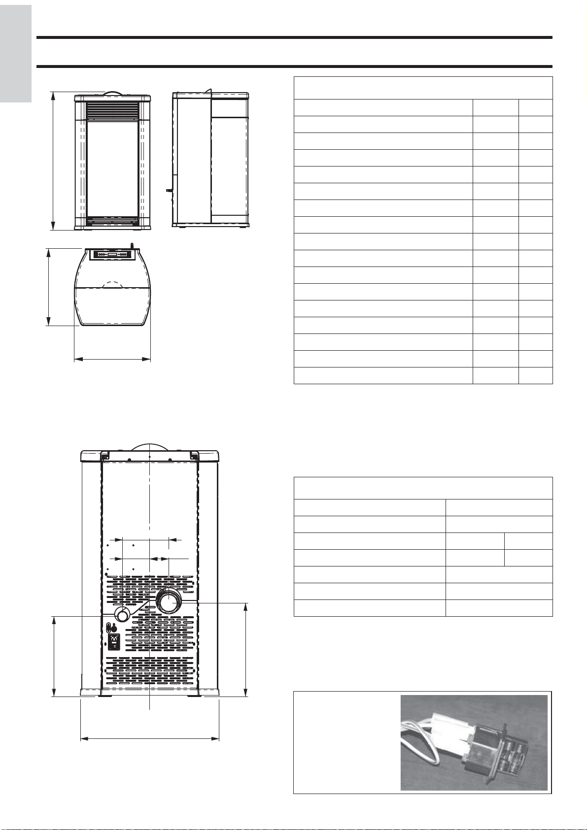
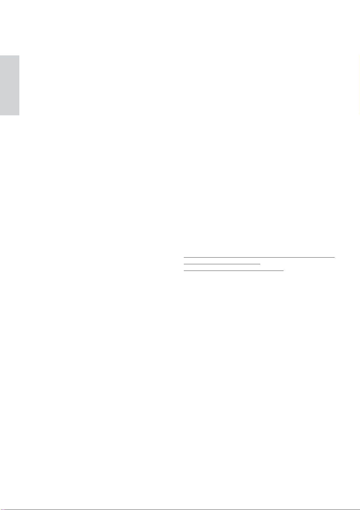
CARATTERISTICHE
ITALIANO
992
99
552
55
55
546
CARATTERISTICHE TERMOTECNICHE
Potenza nominale 8,0 kW
Rendimento potenza nominale 89,2 %
Emissione CO (13% O2) potenza nominale 0,07 %
Massa fumi potenza nominale 5,5 g/s
Potenza ridotta 3,4 kW
Rendimento potenza ridotta 92,6 %
Emissione CO (13% O2) potenza ridotta 0,028 %
Massa fumi potenza ridotta 2,9 g/s
Massima sovratemperatura fumi 175 °C
Tiraggio minimo 12 / 5 Pa
Autonomia min/max 6 / 15 ore
Consumo combustibile min/max 0,8 / 1,9 kg/h
Capacità serbatoio 15 kg
Volume riscaldabile * 210 m³
Peso con imballo (acciaio/ceramica) 169/187 kg
Diametro condotto fumi (maschio) 80 mm
315,2
31,5
18
10,5
181,5
7,5
74,9106,6
368
37
Diametro condotto presa aria (maschio) 40 mm
* Il volume riscaldabile è calcolato considerando l’utilizzo di
pellet con p.c.i. di almeno 4300 Kcal/Kg e un isolamento della
casa come da L 10/91 e successive modifi che e una richiesta di
calore di 33 Kcal/m³ ora.
* E’ importante tenere in considerazione anche la collocazione
della stufa nell’ambiente da scaldare.
CARATTERISTICHE ELETTRICHE
Alimentazione 230Vac +/- 10% 50 Hz
Interruttore on/off si
Potenza assorbita media 150 W
Potenza assorbita in accensione 400 W
Frequenza telecomando (optional) infrarossi
Protezione su alimentazione generale ** Fusibile F4 AL, 250
Protezione su scheda elettronica Fusibile F4 AL, 250
I dati sopra riportati sono indicativi.
EDILKAMIN s.p.a. si riserva di modifi care i propri prodotti
senza preavviso.
55
546
FUSIBILE
* sulla presa con interruttore posta sul retro
della stufa, sono inseriti
due fusibili, di cui uno
funzionale e l’altro di
scorta.
- 4 -
*
*
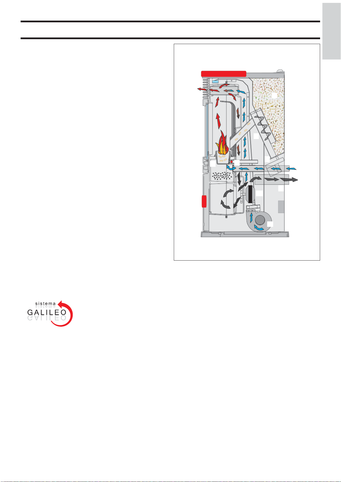
CARATTERISTICHE
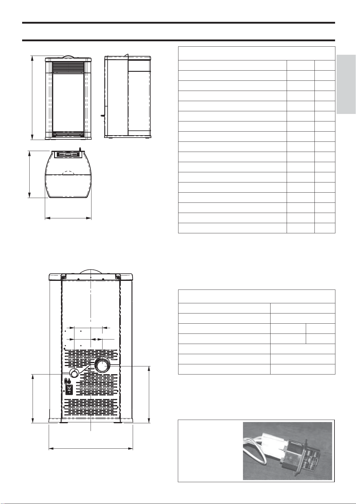
FUNZIONAMENTO
Il combustibile (pellet) viene prelevato dal serbatoio di stoccaggio (A) e, tramite una coclea (B) attivata da motoriduttore
(C) ,viene trasportato nel crogiolo di combustione (D).
L’accensione del pellet avviene tramite aria calda prodotta da
una resistenza elettrica (E) e aspirata nel crogiolo tramite un
ventilatore centrifugo (M).
I fumi prodotti dalla combustione, vengono estratti dal focolare
tramite lo stesso ventilatore centrifugo, ed espulsi dal bocchettone (F) ubicato nella zona bassa del retro della stufa.
Tramite ventilatore (G) viene fatta transitare aria nell’intercapedine sul retro del focolare, dove si riscalda per poi uscire in
ambiente dalla griglia frontale (I).
Il focolare, è realizzato con una struttura interna in ghisa, ed è
chiuso frontalmente da due antine sovrapposte.
- un’antina esterna in vetro ceramico
- un’antina interna in vetro ceramico a contatto con il fuoco.
Il serbatoio del combustibile è ubicato nella parte alta della
stufa. Il riempimento del serbatoio avviene attraverso un coperchio, posto nella parte posteriore del top.
L’alimentazione del combustibile, l’estrazione fumi/alimentazione aria comburente, sono regolate tramite scheda elettronica
(dotata di software con sistema Galileo ) al fi ne di ottenere
una combustione ad alto rendimento e basse emissioni.
Sul top è installato il pannello sinottico (L) che consente la
gestione e la visualizzazione di tutte le fasi di funzionamento.
Le principali fasi possono essere gestite anche attraverso il telecomando fornito optional.
Il rivestimento esterno è disponibile nei seguenti colori e
materiali:
- ceramica: bianco opaco e rossa
- lamiera: fi anchi in alluminio grigio e top in ceramica grigia
- pietra ollare
*
ITALIANO
L
I
A
B
D
E
C
F
M
N
G
*
GALILEO è un sistema di sicurezza e regolazione della combustione che consente un funzionamento ottimale in qualunque
condizione.
GALILEO garantisce un funzionamento ottimale grazie ad un
sensore che misura il fl usso d’aria che partecipa alla combustio-
ne. La rilevazione e la conseguente ottimizzazione dei parametri
di combustione avviene in continuo in modo da correggere in
tempo reale eventuali anomalie di funzionamento.
Il sistema GALILEO ottiene una combustione costante regolando automaticamente il tiraggio in base alle caratteristiche della
canna fumaria (curve, lunghezza, forma, diametro ecc.) ed alle
condizioni ambientali (vento, umidità, pressione atmosferica,
installazioni in alta quota ecc.).
La canna fumaria deve rispettare le normative e le prescrizioni
indicate nella scheda.
- 5 -
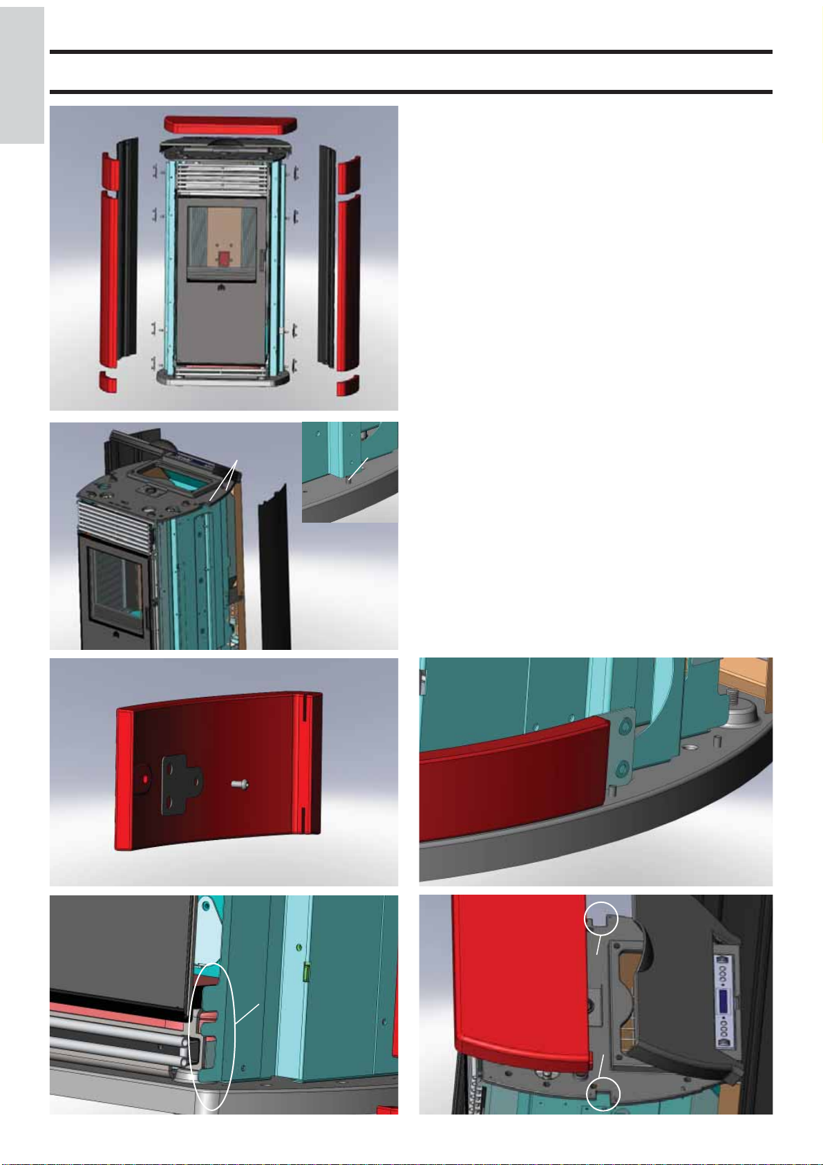
ASSEMBLAGGIO
ITALIANO
1
2
3
fi g. 1
fi g. 2
RIVESTIMENTO
4
5
N
N
N
N
5
1
2
N
N
N
N
3
V
Z
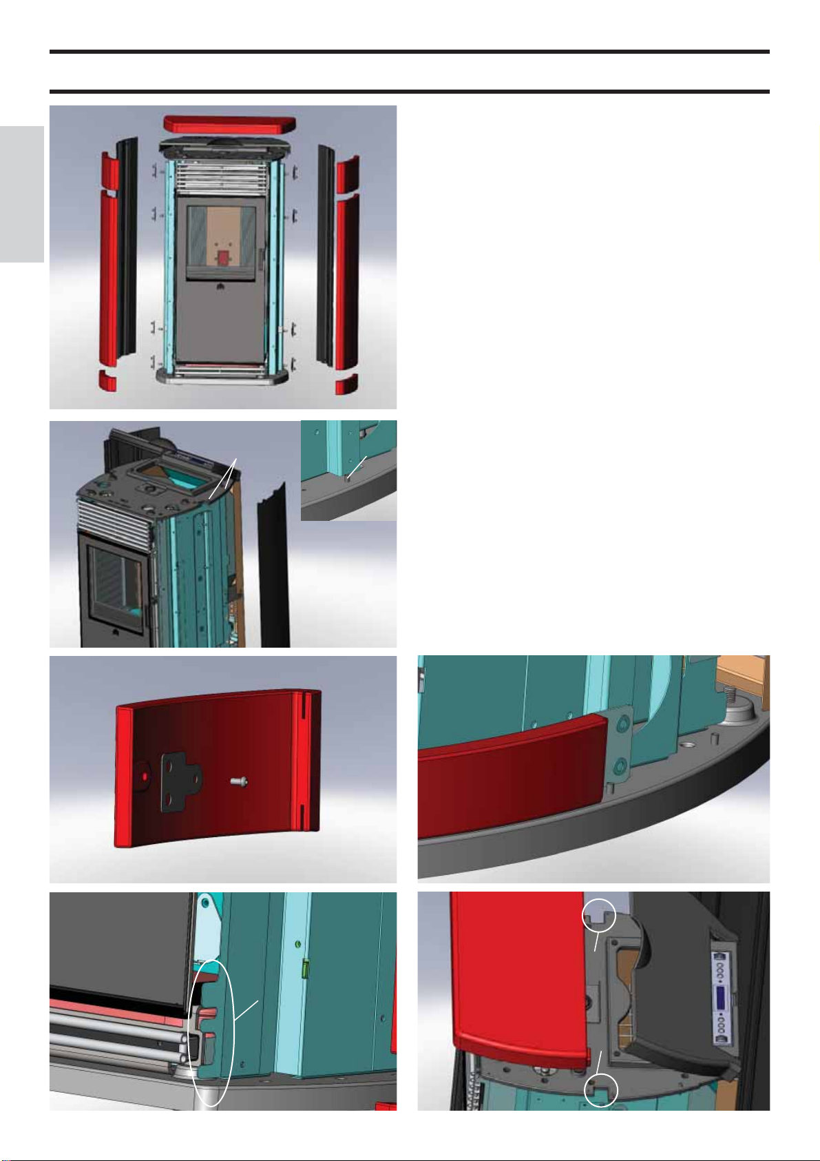
Elenco delle parti costituenti (vedi fi g. 1):
• n° 6 piastrelle laterali in ceramica (1-2-3)
• top in ceramica (4)
• n° 2 fi anchi posteriori in alluminio (5)
• kit fi ssaggio piastrelle in ceramica
Per il montaggio procedere come segue:
- Alzare il top in ghisa, svitare le viti (V) e smontare i due
fi anchi posteriori in alluminio (5) sganciandoli dai perni di
fi ssaggio (Z) posti sul basamento in ghisa fi g. 2.
- Applicare sul retro delle ceramiche (1-2-3) le piastrine (N)
fi ssandole nei fori previsti tramite le viti in dotazione (fi g. 3).
Per caratteristiche di produzione le ceramiche, realizzate a
colaggio, potrebbero risultare leggermente differenti in altezza
l’una dall’altra. Per ovviare all’eventuale variazione di altezza,
è possibile interporre i gommini in dotazione che non pregiudicano in alcun modo l’estetica della stufa.
Interporre tra il basamento in ghisa e la ceramica inferiore (3) i
gommini e la guarnizione in dotazione, mentre tra le ceramiche
(3-2-1) interporre solo i gommini in dotazione.
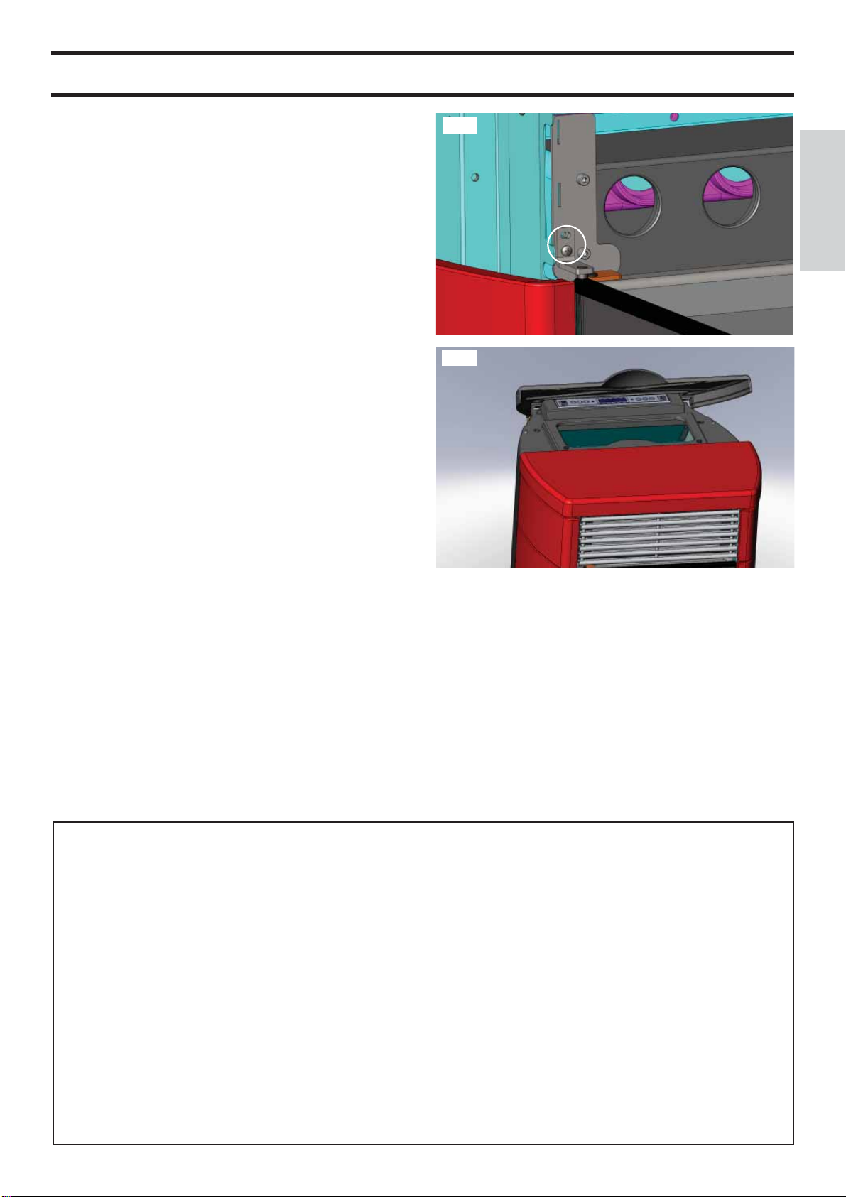
- Accostare dal fi anco ciascun elemento in ceramica facendo
calzare le cave (L presenti all’estremità del bordo anteriore) sul
profi lo verticale in lamiera dentata della struttura (M - fi g. 4).
- Fissare le ceramiche con le piastrine applicate, alla struttura
della stufa utilizzando le viti e le rondelle in dotazione negli
appositi fori (fi g. 5).
fi g. 3
N
5
- Rimontare i due fi anchi posteriori in alluminio (5).
- Posizionare il top in ceramica (4) nelle apposite scanalature
(S-fi g. 6).
NB: Nella versione con rivestimento in lamiera, la stufa
viene fornita già assemblata, tranne il top in ceramica che
deve essere posizionato nelle apposite scanalature (S-fi g. 6).
L
N
L
fi g. 5
fi g. 4
M
- 6 -
fi g. 6
4
S
S
INSTALLAZIONE
MONTAGGIO E INSTALLAZIONE (CAT centro assistenza tecnica)
Per quanto non espressamente riportato, in ogni nazione fare
riferimento alle norme locali. In Italia fare riferimento alla norma UNI 10683/2005, nonché ad eventuali indicazioni regionali
o delle ASL locali. In caso di installazione in condominio o
case di proprietà comune, chiedere parere preventivo all’amministratore.
VERIFICA DI COMPATIBILITA’ CON ALTRI
DISPOSITIVI
La stufa NON deve essere installata nello stesso ambiente
in cui si trovano estrattori, apparecchi a gas di tipo A e B e
comunque altri dispositivi che mettano in depressione il locale
(riferimento UNI 10683/2005).
VERIFICA ALLACCIAMENTO ELETTRICO
(posizionare la spina in un punto accessibile)
La stufa è fornita di un cavo di alimentazione elettrica da collegarsi ad una presa di 230V 50 Hz, preferibilmente con interruttore magnetotermico. Variazioni di tensione superiori al 10%
possono compromettere la stufa (se non già esistente si preveda
un interruttore differenziale adeguato). L’impianto elettrico
deve essere a norma; verifi care in particolare l’effi cienza del
circuito di terra. La linea di alimentazione deve avere una
sezione adeguata alla potenza dell’apparecchiatura.
La non effi cienza del circuito di terra provoca mal funziona-
mento di cui Edilkamin non si può far carico.
DISTANZE DI SICUREZZA PER ANTINCENDIO E POSIZIONAMENTO
Per il corretto funzionamento la stufa deve essere posizionata
in bolla.
Verifi care la capacità portante del pavimento.
La stufa deve essere installata nel rispetto delle seguenti condizioni di sicurezza:
- distanza minima sui lati e sul retro di 40 cm dai materiali
mediamente infi ammabili
- davanti alla stufa non possono essere collocati materiali facilmente infi ammabili a meno di 80 cm
- se la stufa è installata su un pavimento infi ammabile deve
essere interposta una lastra di materiale isolante al calore che
sporga almeno 20 cm sui lati e 40 cm sul fronte.
Se non risultasse possibile prevedere le distanze sopra indicate,
è necessario mettere in atto provvedimenti tecnici ed edili per
evitare ogni rischio di incendio. In caso di collegamento con
parete in legno o altro materiale infi ammabile, è necessario
coibentare il tubo di scarico fumi con fi bra ceramica o altro ma-
teriale di pari caratteristiche.
SCARICO FUMI
Il sistema di scarico deve essere unico per la stufa (non si
ammettono scarichi in canna fumaria comune con altri dispositivi).
Lo scarico dei fumi avviene dal tubo di diametro 8 cm posto
sul retro.
E’ da prevedersi un T con tappo raccolta condense all’inizio
del tratto verticale.
Lo scarico fumi della stufa deve essere collegato con l’esterno
utilizzando tubi in acciaio o neri tubi in acciaio certifi cati EN
1856 senza ostruzioni.
Il tubo deve essere sigillato ermeticamente.
Per la tenuta dei tubi e il loro eventuale isolamento è necessario
utilizzare materiali resistenti alle alte temperature (silicone o
mastici per alte temperature).
L’unico tratto orizzontale ammesso può avere lunghezza fi no
a 2 m. Il tratto orizzontale deve avere una pendenza minima
direzione fumo del 3% verso l’alto.
E’ possibile un numero di curve a 90° fi no a due.
E’ necessario (se lo scarico non si inserisce in una canna fumaria) un tratto verticale e un terminale antivento (riferimento
UNI 10683/2005).
Il condotto verticale può essere interno o esterno. Se il canale
da fumo è all’esterno deve essere coibentato.
Se il canale da fumo si inserisce in una canna fumaria, questa
deve essere autorizzata per combustibili solidi e se più grande di 150 mm di diametro, è necessario risanarla (dopo aver
effettuato la pulizia, per evitare rischi di incendi) intubando e
sigillando lo scarico rispetto alla parte in muratura.
Tutti i tratti del condotto fumi devono essere ispezionabili.
Nel caso sia fi sso deve presentare aperture di ispezione per la
pulizia.
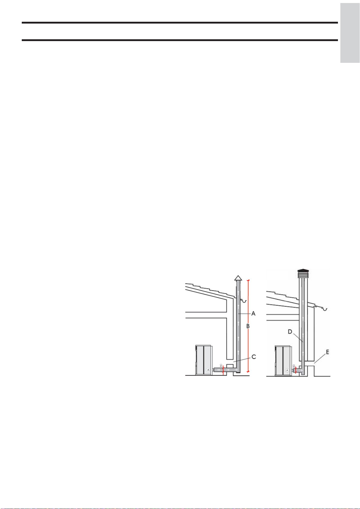
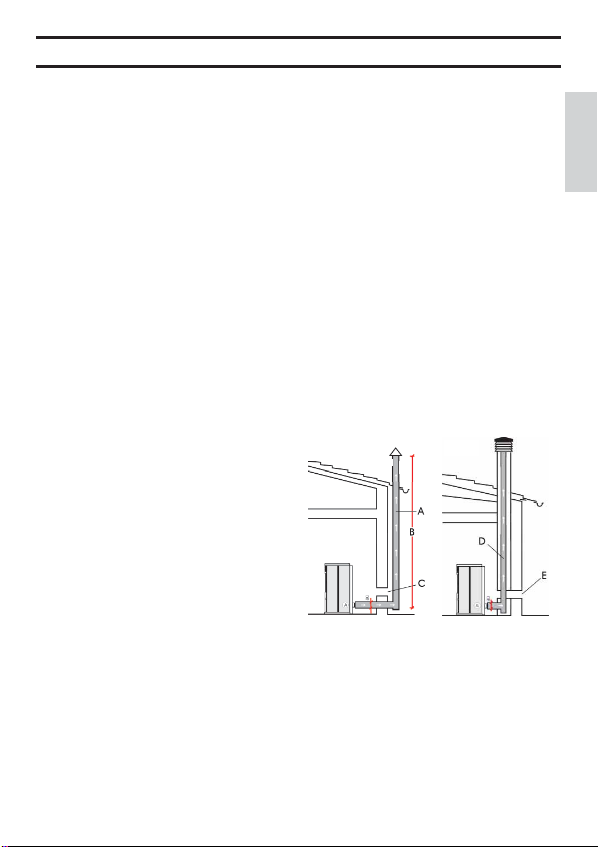
Le possibili installazioni risultano quelle proposte nelle fi gure
1 e 2 .
fi g. 1
fi g. 2
ITALIANO
PRESA D’ARIA
E’ necessario che il locale dove la stufa è collocata abbia una
presa di aria di sezione di almeno 80 cm² che garantisca il ripristino dell’aria consumata per la combustione.
In alternativa, è possibile prelevare l’aria per la stufa direttamente dall’esterno attraverso un prolungamento in acciaio del
tubo di diametro 4 cm ubicato sullo schienale della stufa stessa.
Il tubo deve essere di lunghezza inferiore a 1 metro e non deve
presentare curve. Deve terminare con un tratto a 90° gradi
verso il basso o con una protezione antivento.
In ogni caso lungo tutto il percorso il condotto presa aria deve
essere garantita una sezione libera almeno di 12 cm².
Il terminale esterno del condotto presa aria deve essere protetto
con una rete anti insetti che comunque non riduca la sezione
passante utile di 12 cm².
A: canna fumaria in acciaio coibentata
B: altezza minima 1,5 m e comunque oltre la quota di gronda del
tetto
C-E: presa d’aria dall’ambiente (sezione passante minimo 80
cm²)
D: canna fumaria in acciaio, interna alla canna fumaria esistente
in muratura.
COMIGNOLO
Le caratteristiche fondamentali sono:
- sezione interna alla base uguale a quella della canna fumaria
- sezione di uscita non minore del doppio di quella della canna
fumaria
- posizione in pieno vento, al di sopra del colmo tetto ed al di
fuori delle zone di refl usso.
- 7 -
ISTRUZIONI D’USO
Prima di accendere.
ITALIANO
Per la 1°Accensione è indispensabile rivolgersi al centro
assistenza tecnica Edilkamin, di zona (CAT), (per informazioni
rivolgersi al rivenditore di zona o consultare il sito www.edil-
kamin.com ) che tarerà la stufa in base al tipo di pellet e alle
condizioni di installazione, attivando così la garanzia.
Durante le prime accensioni si possono sviluppare leggeri
odori di vernice che scompariranno in breve tempo.
Prima di accendere è comunque necessario verifi care:
==> La corretta installazione.
==> L’alimentazione elettrica.
==> La chiusura della porta, che deve essere a tenuta.
==> La pulizia del crogiolo.
==> La presenza sul display dell’indicazione di standby
(orario e temperatura).
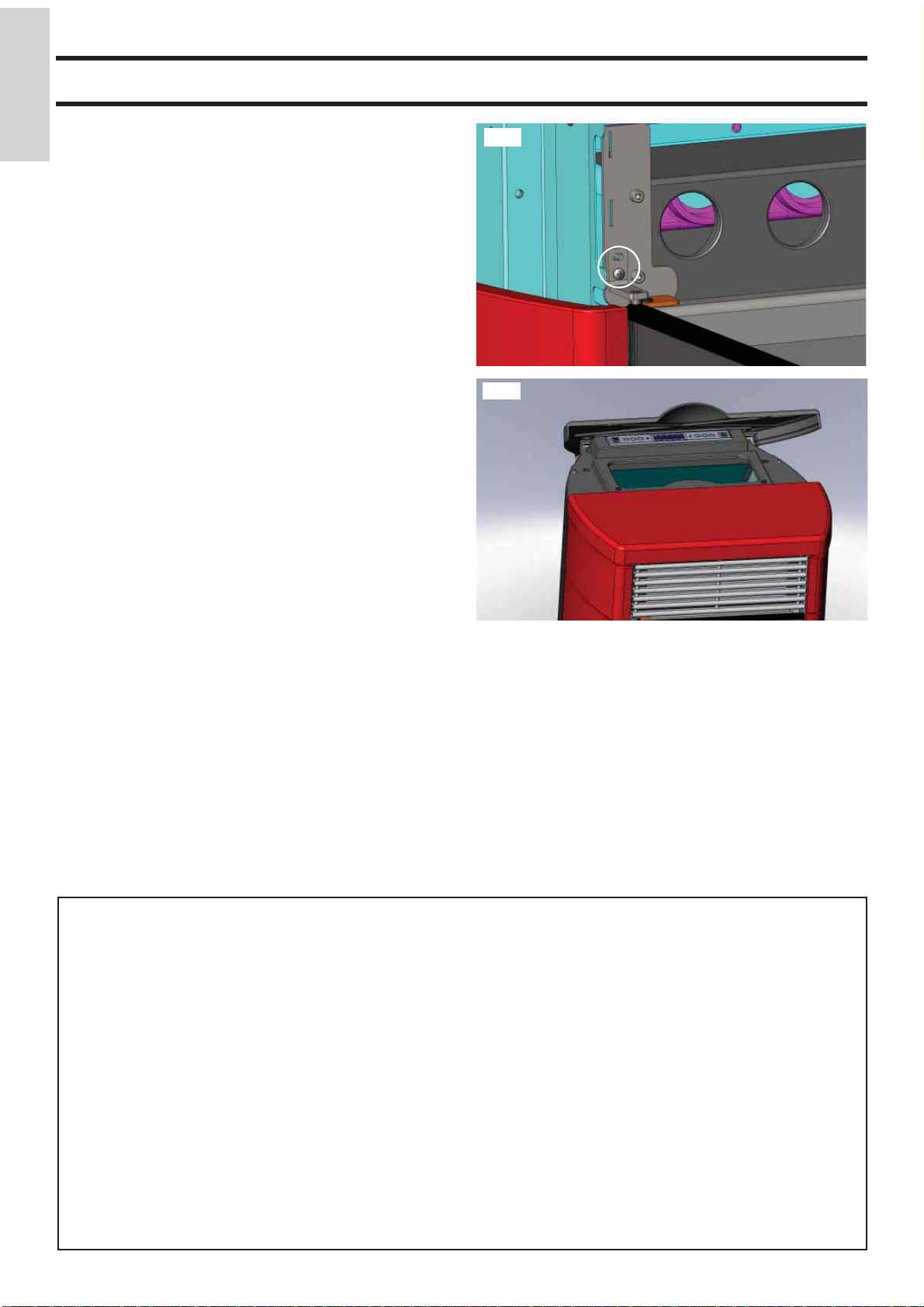
Regolazione anta esterna
Rimuovere la griglia superiore fi ssata a baionetta e regolare
l’allineamento dell’anta esterna con i fi anchi in ceramica o in
alluminio agendo sulle viti V (fi g. 1).
fi g. 1
V
fi g. 2
Caricamento del pellet nel serbatoio
Per accedere al serbatoio sollevare il top in ghisa (fi g. 2).
ATTENZIONE :
utilizzare apposito guanto in dotazione se si carica la stufa
mentre è in funzione e quindi calda.
NOTA sul combustibile.
FLEXA è progettata e programmata per bruciare pellet di
legno di diametro di 6 mm circa.
Il pellet è un combustibile che si presenta in forma di piccoli
cilindretti, ottenuti pressando segatura, ad alti valori, senza
uso di collanti o altri materiali estranei.
E’ commercializzato in sacchetti da 15 Kg.
Per NON compromettere il funzionamento della stufa è indispensabile NON bruciarvi altro.
L’impiego di altri materiali (legna compresa), rilevabile da
analisi di laboratorio, implica la decadenza della garanzia.
Edilkamin ha progettato, testato e programmato i propri prodotti perché garantiscano le migliori prestazioni con pellet
delle seguenti caratteristiche:
diametro : 6 millimetri
lunghezza massima : 40 mm
umidità massima : 8 %
resa calorica : 4300 kcal/kg almeno
L’uso di pellet con diverse caratteristiche implica la necessità
di una specifi ca taratura della stufa, analoga a quella che fa
il CAT (centro assistenza tecnica) alla 1° accensione.
L’uso di pellet non idonei può provocare: diminuzione del
rendimento; anomalie di funzionamento; blocchi per intasamento, sporcamento del vetro, incombusti, …
Una semplice analisi del pellet può essere condotta visivamente:
Buono: liscio, lunghezza regolare, poco polveroso.
Scadente: con spaccature longitudinali e trasversali, molto
polveroso, lunghezza molto variabile e con presenza di
corpi estranei.
- 8 -
ISTRUZIONI D’USO
IL FUNZIONAMENTO
La stufa ha due modalità di funzionamento:
- MANUALE:
Nella modalità di funzionamento MANUALE si imposta la
potenza in cui far lavorare la stufa, indipendentemente dalla
temperatura della stanza in cui è installata.
Per selezionare la modalità di funzionamento MANUALE
premere la manopola sx e impostare la temperatura ambiente
desiderata (SET TEMPERATURA AMBIENTE) oltre 40 °C,
mediante la rotazione della manopola stessa oppure utilizzando
i tasti +/-.
Sul display verrà visualizzata la dicitura “MAN”.
Premendo, e successivamente ruotando la manopola di destra
oppure utilizzando i tasti +/-, si modifi ca la potenza della stufa,
ripremendo la manopola oppure il tasto ON/OFF si conferma
la potenza scelta.
- AUTOMATICA
Nella modalità di funzionamento AUTOMATICA si può
impostare la temperatura obbietivo nel locale dove è installata
la stufa.
La stufa, autonomamente, al raggiungimento della temperatura
ambiente desiderata (SET TEMPERATURA AMBIENTE),
andrà in modulazione portandosi in potenza 1.
Premendo e ruotando la manopola di sinistra oppure utilizzando i tasti +/- si varia la temperatura ambiente desiderata (SET
TEMPERATURA AMBIENTE) a proprio piacimento.
Ripremendo la manopola stessa oppure il tasto ON/OFF si
conferma.
La ventilazione e’sempre correlata alla potenza in uso, quindi
non la si può variare.
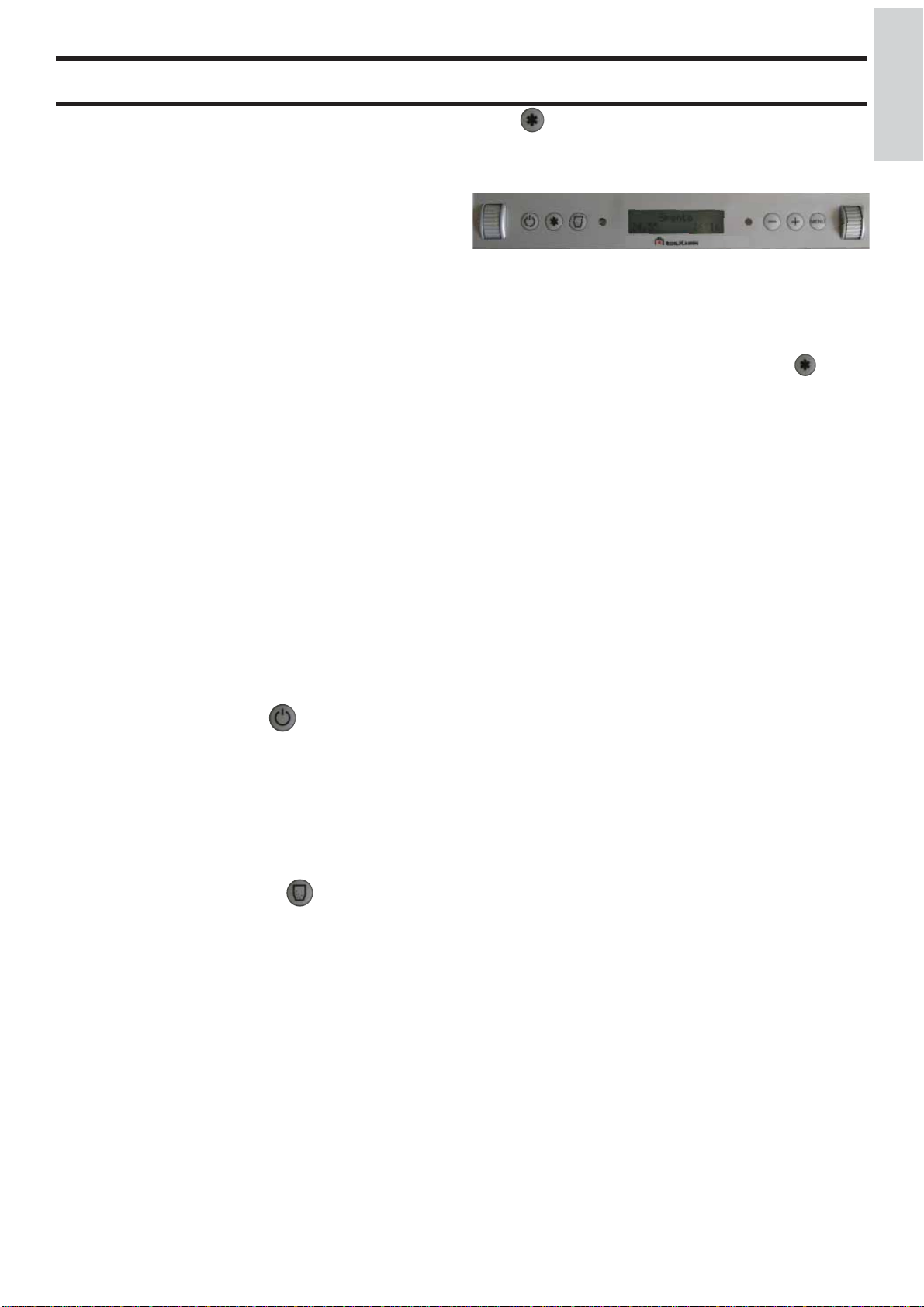
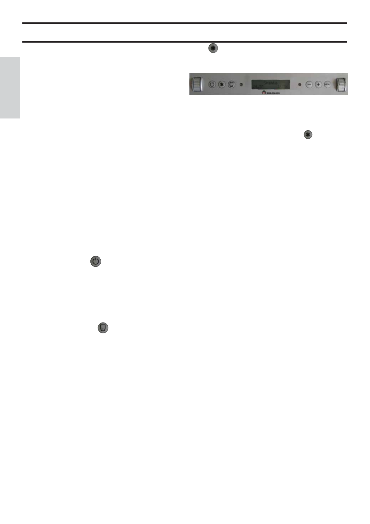
Tasto On/Off del pannello
Accende o spegne la stufa.
All’interno dei menù il tasto On/Off serve per tornare al menù
precedente o uscire dalla modalità.
Tasto +/- del pannello
Aumenta o decrementa i valori che compaiono nelle varie
modalità di funzionamento.
Tasto “riserva” del pannello
Funzione per determinare la quantità di pellet residua all’interno del serbatoio. Tale funzione puo’ essere abilitata o disabilitata tramite il menu utente “variazione riserva”. Premendo il
tasto ‘riserva’, sara’ sommato un valore pari a 15 Kg di default.
Si può variare il valore, entrando nel menù utente “variazione
riserva” e tramite la pressione dei tasti ‘+’ o ‘-‘ si incrementerà
o decrementerà questo valore da un minimo di 5 Kg fi no ad
un massimo di 15 Kg (impostando un valore di 5 Kg, ad ogni
pressione del tasto ‘riserva’ saranno aggiunti 5 chili).
Nel caso di errori è possibile tornare indietro premendo il tasto ‘-’
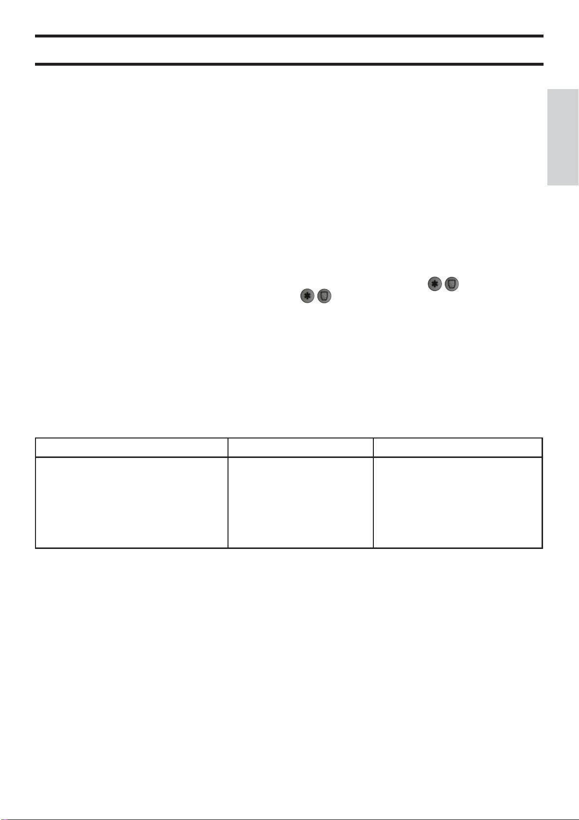
Tasto del pannello
Informa sullo stato della stufa, premuto all’interno dei menù
visualizza il menù/parametro precedente.
manopola sx
pannello
manopola dx
RIEMPIMENTO COCLEA
(solo nel caso che la stufa sia rimasta completamente senza
pellet)
Per caricare la coclea si deve entrare nel MENU’ UTENTE,
nella voce ‘CARICO INIZIALE’ e premere il tasto .
Tale operazione deve essere eseguita solo a stufa spenta e completamente fredda.
ACCENSIONE
Accensione automatica
A stufa in stand-by (scritta visualizzata sul display “SPENTA”), premendo per 2” il tasto on/off si avvia la procedura
di accensione e viene visualizzata la scritta ‘PRECARICO’
(tempo in cui viene caricato un quantitativo di pellet necessario
per l’accensione) seguita da ‘ACCENSIONE’ (tempo in cui
viene accesa la candeletta fi no alla rilevazione della fi amma) e
successivamente ‘ATTESA FIAMMA’ (tempo in cui la stufa
rimane in attesa di rilevare la fi amma).
A rilevazione fi amma si spegne la resistenza elettrica e compa-
re la scritta ‘STABILIZZAZIONE’ (tempo in cui la stufa monitorizza l’aumentare della temperatura fumi che deve rispettare
un aumento di 2 gradi al minuto, in caso contrario entra in
allarme), fi nito tale tempo se tutti i test sono positivi compare
la scritta ‘LAVORO’.
Questa procedura ha una durata di circa 15 minuti.
Spegnimento
A stufa funzionante premendo per 2” il tasto ON/OFF si avvia
la procedura di spegnimento (ventilatori aria in funzione, motoriduttore spento, estrattore fumi in funzione) VENTILATORI
ARIA e viene visualizzato il messaggio ‘STUFA IN SPEGNIMENTO’, questa procedura ha una durata minima di 15 minuti.
Nel caso, trascorso tale tempo la stufa presentasse una temperatura sopra la soglia prevista per lo spegnimento, la procedura
continuerà fi no al raggiungimento di tale soglia.
In caso di blocco della stufa vedere gli allarmi a pagina 14-15
o contattare il Rivenditore di zona o il Centro di Assistenza
Tecnica Autorizzato (CAT).
MENU’ UTENTE
All’interno del display è presente un ‘MENU’ UTENTE’ le cui
funzioni devono essere variate dal CAT.
ITALIANO
- 9 -
ISTRUZIONI D’USO
REGOLAZIONE ORARIO E DATA
ITALIANO
Premendo il tasto ‘menù’ e ruotando la manopola sx si visualizza a display la scritta ‘SET OROLOGIO’.
Premendo di nuovo il tasto ‘menù’ e ruotando la manopola sx appaiono in sequenza i seguenti dati: Giorno della settimana, ora,
minuti, giorno, mese, anno che possono essere variati con la manopola dx.
Ad ogni scatto della manopola sx il valore sarà confermato,.
Premendo il tasto ON/OFF o la manopola stessa si esce dalla programmazione.
ESEMPIO DI REGOLAZIONE:
Set orologio Giorno martedi Set orologio Ore 15: Set orologio Minuti :00
Set orologio Giorno 7 Set orologio mese 6 Set orologio anno 11
CRONOTERMOSTATO PER LA PROGRAMMAZIONE GIORNALIERA/SETTIMANALE
Sono previste 3 modalità di programmazione (giornaliera, settimanale, week end), ognuna delle quali e’ indipendente dall’altra
consentendo così molteplici combinazioni per le proprie esigenze (e’ possibile regolare gli orari con passo di 10 minuti).
Premendo il tasto ‘menù’ si visualizza a display la scritta ‘SET CRONO’, premendo successivamente il tasto ‘menù’ o premendo
la manopola di dx si accede al ‘SET CRONO’ visualizzando a display la scritta ‘ABILITA CRONO’ (di default è impostato in
OFF).
Per visualizzare le 3 modalità di programmazione (giornaliera, settimanale, week end) ruotare la manopola di sx oppure utilizzare
i tasti .
Per impostare le accensioni e gli spegnimenti utilizzare la manopola sx oppure i tasti .
Per variare gli orari delle accensioni e degli spegnimenti utilizzare la manopola dx oppure i tasti +/-.
Per uscire dalla programmazione selezionata utilizzare il tasto ON/OFF.
Programmazione Giornaliera:
possibilità di 2 accensioni/spegnimenti nell’arco della giornata ripetuti per tutti i giorni:
Esempio: start1 10:00 stop1 12:00 start2 18:00 stop2 22:00
Programmazione Settimanale:
possibilità di 4 accensioni/spegnimenti nella giornata scegliendo i giorni della settimana, esempio:
start1 06:00 stop1 08:00 start2 07:00 stop2 10:00 start3 19:00 stop3 22:00….
lunedi on
martedi on
mercoledi off
giovedi on
venerdi on
sabato off
domenica off
Programmazione Week-end:
possibilità di 2 accensioni/spegnimenti durante il week-end:
Esempio: start1 week-end 07:00 stop1 week-end 11:30
Esempio: start2 week-end 14:20 stop2 week-end 23:50
Con il cronotermostato attivo sarà visibile, accanto all’orario, un’icona che rappresenta l‘orologio.
lunedi off
martedi off
mercoledi on
giovedi off
venerdi off
sabato off
domenica off
lunedi on
martedi on
mercoledi on
giovedi on
venerdi on
sabato on
domenica on
- 10 -
APPARATI ELETTRONICI
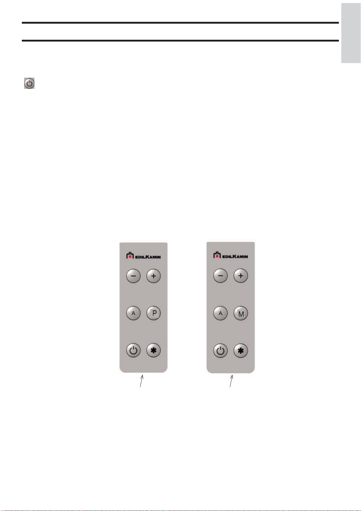
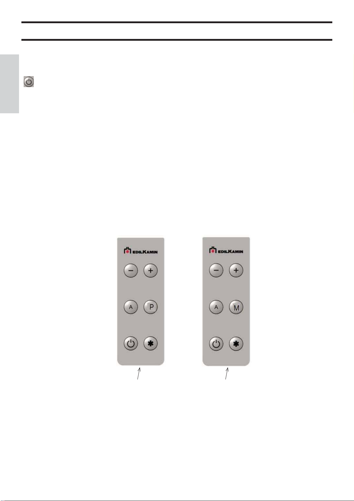
TELECOMANDO cod. 658830 - optional
LEGENDA SIMBOLI
N.B:secondo i lotti di produzione potranno essere utilizzati due diversi simboli per il tasto potenza (X - vedi fi g. 1-2)
: tasto accensione/spegnimento
+ : tasto per incrementare la potenza/temperatura di lavoro
- : tasto per decrementare la potenza/temperatura di lavoro
A : tasto “AMBIENTE”; varia la la temperatura ambiente desiderata (SET AMBIENTE)
P (fi g. 1) M (fi g. 2) : tasto “POTENZA”; varia la potenza (da P1 a P5)
- Il telecomando trasmette con segnale infrarosso.
Il led di trasmissione segnale deve essere in linea visiva con il led di ricezione della stufa perché vi sia una corretta trasmissione.
In campo libero, la operatività è di 4-5mt.
- Il telecomando funziona con una batteria alcalina da 3V, la durata della batteria dipende dell’uso ma copre comunque abbondantemente l’utilizzo dell’utente medio per un’intera stagione.
Per la sostituzione rimuovere lo sportellino Y dove è alloggiata la batteria.
La batteria esaurita deve essere smaltita opportunamente in base ai regolamenti vigenti.
- Il telecomando deve essere pulito con un panno umido senza spruzzare prodotti detergenti o liquidi direttamente su di esso, usare
in ogni caso detergenti neutri privi di sostanze aggressive.
- Maneggiare con cura il telecomando, una caduta accidentale potrebbe provocarne la rottura.
ITALIANO
(X)
fi g. 1 fi g. 2
Y Y
NOTE:
- Temperatura di lavoro: 0-40°C
- Temperatura di stoccaggio : -10/+50°C
- Umidità di lavoro: 20-90% U.R. senza condensa
- Grado di protezione: IP 40
- Peso con pila inserita: 15 gr
(X)
- 11 -
ITALIANO
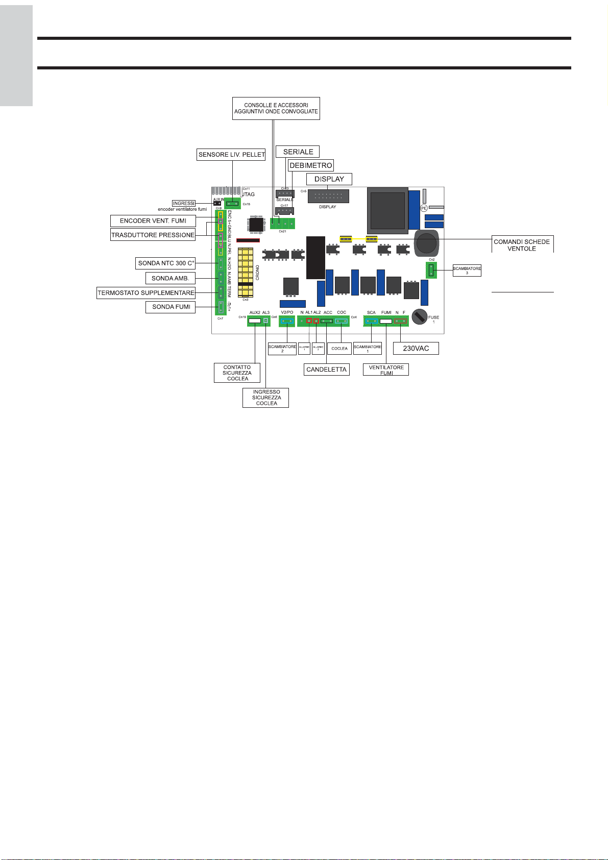
SCHEDA ELETTRONICA
*
APPARATI ELETTRONICI
BATTERIA
TAMPONE
DISPOSITIVI di SICUREZZA
TERMOCOPPIA:
Posta sullo scarico fumi ne rileva la temperatura.
In funzione dei parametri impostati controlla le fasi di accensione, lavoro e spegnimento.
SENSORE FLUSSO ARIA (DEBIMETRO):
Posto nel canale d’aspirazione, interviene quando il fl usso
dell’aria comburente è non corretto, provocando quindi problemi di depressione nel circuito fumi.
TERMOSTATO DI SICUREZZA:
Interviene nel caso in cui la temperatura all’interno della stufa
è troppo elevata.
Blocca il caricamento del pellet provocando lo spegnimento
della stufa (vedi allarme A09 a pag. 14).
ACCENSIONI REMOTE
Nella scheda elettronica e’ presente un ingresso (contatto
pulito termostato supplementare *) il quale può essere usato
per accensioni remote tramite termostati esterni.
L’installazione di questi dispositivi deve essere eseguita da
CAT autorizzati tramite cavetto optional cod. 640560.
BATTERIA TAMPONE
Sulla scheda elettronica è presente una batteria tampone (tipo
CR 2032 da 3 Volt).
Per maggiori riferimenti all’occorrenza, contattare il CAT che
ha effettuato la 1° accensione.
- 12 -

MANUTENZIONE
Prima di effettuare qualsiasi manutenzione, scollegare l’apparecchio dalla rete di alimentazione elettrica.
LA MANCATA MANUTENZIONE NON permette alla stufa di funzionare regolarmente.
Eventuali problemi dovuti alla mancata manutenzione sono causa di decadenza della garanzia.
MANUTENZIONE GIORNALIERA
Operazioni da eseguire, a stufa spenta, fredda e scollegata dalla rete elettrica
Deve essere effettuata con l’aiuto di un aspirapolvere (vedi optional pag. 15), l’intera procedura richiede pochi minuti.
- Aspirare lo sportello, aspirare il piano fuoco, aspirare il vano attorno al crogiolo dove cade la cenere
- Togliere il crogiolo o scrostarlo con la spatolina in dotazione, pulire eventuali occlusioni dei i fori su tutti i lati.
- Aspirare il vano crogiolo, pulire i bordi di appoggio del crogiolo sulla sua sede, rimettere il crogiolo.
- Se necessario pulire il vetro (a freddo).
NON ASPIRARE MAI LA CENERE CALDA, comprometterebbe l’aspirapolvere impiegato con rischio di incendio.
MANUTENZIONE STAGIONALE (a cura del CAT - centro assistenza tecnica)
- Pulizia generale interna ed esterna.
- Pulizia accurata dei tubi di scambio.
- Pulizia/controllo dei tubi di scarico.
- NON allentare mai le brugole interne al focolare: cadrebbe il caricatore
- Pulizia accurata e disincrostazione del crogiolo e del relativo vano.
- Pulizia ventilatori, verifi ca meccanica dei giochi e dei fi ssaggi.
- Pulizia canale da fumo (sostituzione della guarnizione sul tubo scarico fumi).
- Pulizia del vano ventilatore estrazione fumi, pulizia sensore di fl usso, controllo termocoppia.
- Pulizia, ispezione e disincrostazione del vano della resistenza di accensione, eventuale sostituzione della stessa.
- Pulizia /controllo del Pannello Sinottico.
- Ispezione visiva dei cavi elettrici, delle connessioni e del cavo di alimentazione.
- Pulizia serbatoio pellet e verifi ca giochi assieme coclea-motoriduttore.
- Sostituzione della guarnizione portello.
- Collaudo funzionale, caricamento coclea, accensione, funzionamento per 10 minuti e spegnimento.
ITALIANO
Se vi è un uso molto frequente della stufa, si consiglia la pulizia del canale da fumo ogni 3 mesi.
RICORDARSI di ASPIRARE il CROGIOLO PRIMA DI OGNI ACCENSIONE
In caso di fallita accensione, NON ripetere l’accensione prima di avere svuotato il crogiolo
ATTENZIONE: IL PELLET SVUOTATO DAL CROGIOLO
NON DEVE ESSERE DEPOSITATO NEL SERBATOIO.
- 13 -

CONSIGLI PER POSSIBILI INCONVENIENTI
In caso di problemi la stufa si arresta automaticamente eseguendo l’operazione di spegnimento e sul display si visualizza
ITALIANO
una scritta relativa alla motivazione dello spegnimento (vedi sotto le varie segnalazioni).
Non staccare mai la spina durante la fase di spegnimento per blocco.
Nel caso di avvenuto blocco, per riavviare la stufa è necessario lasciar avvenire la procedura di spegnimento (15 minuti
con riscontro sonoro) e quindi premere il tasto ON/OFF.
Non riaccendere la stufa prima di aver verifi cato la causa del blocco e RIPULITO/SVUOTATO il crogiolo.
SEGNALAZIONI DI EVENTUALI CAUSE DI BLOCCO E INDICAZIONI E RIMEDI:
A01 mancata accensione
(avviene quando in fase di accensione la temperatura dei fumi non supera la soglia minima)
• Crogiolo sporco o troppo pellet
• E’ fi nito il pellet
• Canna fumaria ostruita
• Probabile resistenza elettrica guasta
A03 tiraggio insuffi ciente
(avviene quando il fl usso dell’aria comburente scende sotto la soglia minima consentita)
• Canna fumaria ostruita
• Porta aperta
• Crogiolo intasato
• Debimetro (sensore fl usso aria) sporco
• Guarnizione porta da sostituire
A05 hot fumi
(avviene quando la temperatura dei fumi supera una temperatura di sicurezza)
• Canna fumaria ostruita
• Installazione non corretta
• Stufa intasata
• Carico pellet alto, controllare regolazione pellet (CAT)
A06 manca pellet
(avviene quando fi nisce il pellet; lampeggia display preceduto da un bip” sonoro)
• Esaurito pellet nel serbatoio
• Motoriduttore guasto
• Condotto/coclea pellet ostruito
• Carico pellet basso, controllare regolazione pellet
A07 sonda fumi rotta (avviene quando la stufa non legge più la sonda)
• Termocoppia rotta
• Termocoppia scollegata
A08 black out (non è un difetto della stufa)
(avviene se c’è stata un’assenza di tensione di rete elettrica superiore a 5 secondi)
Nella stufa è presente la funzione di ‘black out’.
In caso di interruzione di energia elettrica, con un tempo inferiore a 5 secondi, la stufa si riaccenderà ritornando nella funzione
precedente allo spegnimento.
Nel caso tale tempo sia superiore, la stufa si posizionerà in allarme ‘black out’, con conseguente fase di raffreddamento.
Qui di seguito un elenco delle varie possibilità:
Stato stufa prima del black-out
OFF OFF OFF
Tempo interruzione inferiore
PR “ritardo black out”
Tempo interruzione superiore
PR “ritardo black out”
PRECARICA BLACK OUT BLACK OUT
ACCENSIONE BLACK OUT BLACK OUT
AVVIO AVVIO STAND-BY POI RIACCENSIONE
LAVORO LAVORO STAND-BY POI RIACCENSIONE
PULIZIA FINALE PULIZIA FINALE PULIZIA FINALE
STAND-BY STAND-BY STAND-BY
ALLARME ALLARME ALLARME
MEMORIA ALLARME MEMORIA ALLARME MEMORIA ALLARME
- 14 -
CONSIGLI PER POSSIBILI INCONVENIENTI
A09 sicurezza termica
(avviene quando il termostato di sicurezza, situato a contatto del serbatoio, scatta per una sovratemperatura del serbatoio pellet,
per riarmare premere il pulsante rosso sul fi anco destro della stufa dopo aver rimosso il cappuccio nero di protezione).
• Carico eccessivo di pellet nel crogiolo
• Stufa/canna fumaria sporca
A11 errore triac
(avviene in caso di guasto della scheda)
• verifi ca del guasto da parte del tecnico
• sostituzione della scheda elettronica
A12 guasto estrattore
(avviene quando la scheda elettronica non legge i giri dell’estrattore fumi; chiamare il CAT)
• Estrattore fumi bloccato
• Sensore giri guasto
• Estrattore fumi guasto
• Intervento termostato motore fumi
• Mancanza messa a terra
• Scheda elettronica difettosa
ITALIANO
- 15 -
CHECK LIST
ITALIANO
Posa e installazione
• Messa in servizio effettuata da CAT abilitato che ha rilasciato la garanzia e il libretto di manutenzione
• Aerazione nel locale
• Il canale da fumo/ la canna fumaria riceve solo lo scarico della stufa
• Il canale da fumo presenta: massimo 2 curve
massimo 2 metri in orizzontale
• comignolo oltre la zona di refl usso
• i tubi di scarico sono in materiale idoneo (consigliato acciaio inox)
• nell’attraversamento di eventuali materiali infi ammabili (es. legno) sono state prese tutte le precauzioni per
evitare incendi
Uso
• Il pellet utilizzato è di buona qualità e non umido
• Il crogiolo e il vano cenere sono puliti e ben posizionati
• Il portello è ben chiuso
• Il crogiolo è ben inserito nell’apposito vano
RICORDARSI di ASPIRARE il CROGIOLO PRIMA DI OGNI ACCENSIONE
In caso di fallita accensione, NON ripetere l’accensione prima di avere svuotato il crogiolo
Da integrare con la lettura completa della scheda tecnica
OPTIONAL
TELECOMANDO (OPTIONAL cod. 658830)
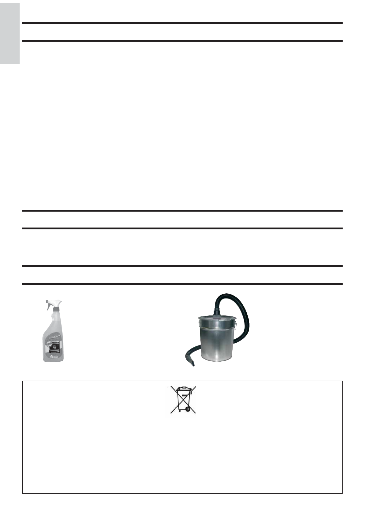
ACCESSORI PER LA PULIZIA
GlassKamin
(cod. 155240)
Utile per la pulizia
del vetro ceramico.
Bidone aspiracenere
senza motore
(cod. 275400)
Utile per la pulizia del
focolare.
INFORMAZIONI AGLI UTENTI
Ai sensi dell’art.13 del decreto legislativo 25 luglio 2005, n.151 ”Attuazione delle Direttive 2002/95/CE,2002/96/CE e
2003/108/CE, relative alla riduzione dell’uso di sostanze pericolose nelle apparecchiature elettriche ed elettroniche, nonché
allo smaltimento dei rifi uti”.
Il simbolo del cassonetto barrato riportato sull’apparecchiatura o sulla confezione indica che il prodotto alla fi ne della propria
vita utile deve essere raccolto separatamente dagli altri rifi uti.
L’utente dovrà, pertanto, conferire l’apparecchiatura giunta a fi ne vita agli idonei centri di raccolta differenziata dei rifi uti
elettronici ed elettrotecnici, oppure riconsegnarla al rivenditore al momento dell’acquisto di una nuova apparecchiatura di
tipo equivalente, in ragione di uno a uno.
- 16 -

Dear Sir/Madam
Congratulations and thank you for choosing our product.
Please read this document carefully before you use this product in order to obtain the best performance in complete
safety.
For further details or assistance, please contact the DEALER where you purchased the product or visit our website
www.edilkamin.com. and click on DEALERS.
NOTE
- After having unpacked the stove, ensure that its contents are complete and intact (covering, remote control with display,
“cold hand” handle, guarantee booklet, glove, specifi cations, spatula, dehumidifying salt, allen wrench).
In case of anomalies please contact the dealer where you purchased the product immediately.
You will need to present a copy of the warranty booklet and valid proof of purchase.
- Commissioning/ testing
Commissioning and testing must be performed by the DEALER. Failure to do so will void the warranty.
Commissioning, as specifi ed in standard UNI 10683 Rev. 2005 (section “3.2”) consists in a series inspections to be
performed with the insert installed in order to ascertain the correct operation of the system and its compliance to
applicable regulations.
- Incorrect installation, incorrect maintenance, or improper use of the product, shall relieve the manufacturer from any damage
resulting from the use of this product.
- the proof of purchase tag, necessary for identifying the stove, is located:
- on the top of the package
- in the warranty booklet found inside the fi rebox
- on the ID plate affi xed to the back side of the unit;
ENGLISH
This documentation must be saved for identifi cation together with the valid proof of purchase receipt. The data contained
therein must be reported when requesting information and made available should servicing be required;
- All images are for illustration purposes only; actual products may vary.
- 17 -
SAFETY INFORMATION
FLEXA is designed to heat the room where they are placed,
by means of radiation and air movement that is let out from
the front grilles, through automatic pellet combustion in the
hearth, and adjoining rooms through air movement analysed
by the pipes on the back.
• The only risks that may derive from using the stove pertain
to non-compliance with installation instructions, direct contact
with live electrical parts (internal), contact with the fi re or hot
parts (glass, pipes, hot air output), or foreign substances being
ENGLISH
put in the stove.
• Only use wood pellets as fuel.
• Should components fail, the stoves are equipped with safety
devices that guarantee automatic shutdown. These are activated
without any intervention required.
• In order to function correctly, the stove must be installed in
accordance with the instructions given herein and the door
must not be opened during operation: combustion is fully
automatic and requires no intervention.
• Under no circumstances should any foreign substances be
entered into the hearth or hopper.
• Do not use fl ammable products to clean the smoke channel
(the fl ue section connecting the stove smoke outlet to the
chimney fl ue).
• Hearth and hopper components must only be cleaned with a
vacuum cleaner.
• Ensure that the stoves are installed and ignited by a qualifi ed
Edilkamin DEALER, in accordance with the instructions
given herein.
• When the stove is in operation, the exhaust pipes and door
become very hot (do not touch without wearing the thermal
glove).
• Do not place anything, which is not heat resistant near the
stove.
• NEVER use liquid fuel to ignite the stove or rekindle the
embers.
• Do not obstruct the ventilation apertures in the room where
the stove is installed, nor the air inlets of the stove itself.
• Do not wet the stove and do not go near electrical parts
with wet hands.
• Do not use reducers on the smoke exhaust pipes.
• The stove must be installed in a room that is suitable for
fi re prevention and equipped with all that is required (power
and air supply and outlets) for the stove to function correctly
and safely.
ATTENTION:
• SHOULD IGNITION FAIL, DO NOT RE-IGNITE
UNTIL YOU HAVE EMPTIED THE COMBUSTION
CHAMBER.
• The glass can be cleaned when COLD with a suitable product
(e.g. GlassKamin Edilkamin) and a cloth.
• Do not clean when hot.
The undersigned EDILKAMIN S.p.a. with head offi ce headquar-
ters at Via Vincenzo Monti 47 - 20123 Milan - Italy - VAT
IT00192220192
Declares under its own responsability as follows:
The pellet stove illustrated below conforms to Regulation EU
305/2011 (CPR) and to the harmonised European Standard
EN 14785:2006
WOOD PELLET STOVES, trademark EDILKAMIN, called
FLEXA
Year of manufacture: Ref. Data nameplate
Declaration of performance (DoP - EK 057): Ref. data tag plate
In addition, it is hereby declared that:
the wood pellet stove FLEXA is in compliance with the requirements of the European directives:
2006/95/EC - Low voltage directive
2004/108/EC - Electromagnetic compatibility directive
• THE PELLET EMPTIED FROM THE COMBUSTION
CHAMBER MUST NOT BE
DEPOSITED INSIDE THE HOPPER.
EDILKAMIN S.p.a. will decline all responsability of malfunctioning or damage to the equipment in case of unauthorized
substitution, assembly or modifi cations of any sort on the said
equipment on the part of non-EDILKAMIN personnel.
- 18 -
FEATURES
THERMOTECHNICAL CHARACTERISTICS
Nominal power 8,0 kW
Effi ciency nominal power 89,2 %
Emissions CO (13% O2) nominal power 0,07 %
992
99
552
55
55
546
Smoke mass nominal power 5,5 g/s
Reduced power 3,4 kW
Effi ciency reduced power 92,6 %
Emissions CO (13% O2) reduced power 0,028 %
Smoke mass reduced power 2,9 g/s
Maximum overheated smoke 175 °C
Minimum draught 12 / 5 Pa
Autonomy (min/max) 6 / 15 hours
Fuel consumption (min/max) 0,8 / 1,9 kg/h
Hopper capacity 15 kg
Heatable volume * 210 m³
Weight including packaging (steel/ceramic) 169/187 kg
Smoke outlet pipe diameter (male) 80 mm
Air intake pipe diameter (male) 40 mm
* The heatable room dimensions are calculated on the basis of
pellets with an lhv of at least 4300 kcal/kg and home insulation
in compliance with Italian law 10/91, and subsequent changes
together with an expected heat output of 33 Kcal/m³ per hour.
* It is also important to consider the position of the stove in the
room to be heated.
ENGLISH
315,2
31,5
18
10,5
181,5
55
546
7,5
74,9106,6
368
37
ELECTRICAL CHARACTERISTICS
Power supply 230Vac +/- 10% 50 Hz
On/off switch Yes
Average power consumption 150 W
Power consumption during ignition 400 W
Remote control frequency Infrared
Protection on mains power supply** F4 AL, 250 Fuse
Protection on electronic circuit board F4 AL, 250 Fuse
The data shown above is purely indicative.
EDILKAMIN s.p.a. reserves the right to make changes to
these products to improve their performance with no prior
warning.
FUSE
* two fuses are inserted
on the socket behind
the stove, fi tted with a
switch one is functional
and the other is spare.
- 19 -
*
*
FEATURES
PRINCIPLE OF OPERATION
The fuel (pellets) is transferred from the storage hopper (A)
to the combustion chamber (D) by means of a feed screw (B),
which is driven by a gear motor (C). The pellets are ignited by
the air that is heated by an electrical resistance (E) and drawn
into the combustion chamber by a centrifugal fan (M). The
fumes produced during the combustion process are extracted
from the hearth by the same centrifugal fan (M) and expelled
ENGLISH
through the outlet (F) located on the lower part at the back of
the stove.
Air is blown into the hollow space at the back of the fi rebox by
a fan (G), where it is heated before coming out into the room
from the front grille (I).
The hearth is made with an internal cast iron structure, and is
closed in the front by two overlapping doors.
- external glass ceramic door
- an inner door made from ceramic glass which is in direct
contact with the fi re.
The pellet hopper is at the top of the stove.The hopper is fi lled
through a lid found at the back of the top
Fuel quantity, smoke extraction and combustion air supply
are all controlled by an electronic control board, which is
equipped with Galileo
effi ciency and low emissions.
The synoptic panel (L) is installed on the top, through which
all phases of operation can be displayed and controlled.
The main phases can be managed via the optionally supplied
remote control.
The external covering is available in the following colours and
materials:
- ceramic: opaque white, red
- plating: grey steel sides, grey ceramic top
- ollare stone
software to achieve high combustion
*
L
I
A
B
D
E
C
F
M
N
G
*
GALILEO is a combustion safety and control system which allows optimal performance in all
conditions.
GALILEO guarantees optimal functions thanks to a sensor that
measures the air fl ow contributing to combustion.
The surveying and consequent optimisation of the combustion
parameters takes place in a continuous way, so as to correct any
possible functioning anomalies in real time
The GALILEO system offers constant combustion, automatically regulating the draft based on the characteristics
of the chimney fl ue (bends, length, shape, diameter, etc..) and
environmental conditions (wind, humidity, atmospheric
pressure, installations at high altitude, etc.). The standards for
installation must be respected.
- 20 -
INSTALLATION
ASSEMBLY AND INSTALLATION (Dealer)
Refer to local regulations in the country of use for anything
that is not specifi cally covered in this manual. In Italy, refer
to standard UNI 10683/2005 in addition to any Regional or
Local Health Authority regulations.
If the stove is to be installed in a block of apartments, consult
the block administration before installing.
VERIFY COMPATIBILITY WITH OTHER
DEVICES
The stove must NOT be installed in the same room as extractors, type B heating appliances and other appliances that may
affect its operation.
VERIFYTHE POWER SUPPLYCONNECTION
The stove is supplied with a power cable that is to be connected to a 230V 50 Hz socket, preferably fi tted with a
magnetothermic switch. Voltage variations exceeding 10%
can damage the stove (unless already installed, an appropriate
differential switch must be fi tted). The electrical system must
comply with the law; particularly verify the effi ciency of the
earthing system. The power line must have a suitable crosssection for the stove’s power. An inadequate earthing system
can cause anomalies for which Edilkamin cannot be held
liable.
(the plug must be accessible)
FIRE SAFETY DISTANCES AND LOCATION
For correct operation the stove must be level.Check the loadbearing capacity of the fl oor.The stove must be installed in
compliance with the following safety conditions:
- minimum safety distance at the sides and back from medium
level fl ammable materials: 40 cm
- easily fl ammable materials must not be located less than 80
cm from the front of the stove
- if the stove is installed on a fl ammable fl oor, a sheet of heat
insulating material must be placed between the stove andthe
fl oor, which protrudes by at least 20 cm at the sides and 40 cm
at the front.
If it is impossible to comply with the distances given above,
technical/building measures must be taken to avoid all fi re
risks.If the smoke outlet pipe is connected to walls made of
wood or other fl ammable materials, it must be insulated with
ceramic fi bre or other materials with similar characteristics.
SMOKE OUTLET
The stove must have its own smoke outlet (the smoke cannot
be discharged into a smoke fl ue used by other devices). The
smoke is discharged through the 8 cm diameter outlet at the
back of the stove.
A T-section with condensation trap and bleeder must be fi tted
at the beginning of the vertical section.
The smoke outlet must be connected to outside by means of
suitable steel pipes EN 1856 certifi ed.
The pipe must be hermetically sealed. The material used to seal
and if necessary insulate the pipes, must be resistant to high
temperatures (high temperature silicone or mastic).
The only horizontal section allowed may be up to 2 m long.
It may have up to two 90° bends. If the outlet is not fi tted into
a chimney fl ue, a vertical section and a wind guard are required
(reference UNI 10683/2005).
The vertical duct can be internal or external. If the smoke
channel is outside, it must be appropriately insulated. If the
smoke channel is fi tted inside a chimney fl ue, the latter must be
suitable for solid fuel. If it is wider than 150 mm in diameter it
must be improved by entering a pipe that has a suitable crosssection and is made of suitable material (e.g. 80 mm diameter
steel). All sections of the smoke duct must be accessible for
inspection. The chimney pots and smoke ducts connected to
the solid fuel appliances must be cleaned once a year (verify
whether a specifi c legislation exists in your country). Failure to
regularly inspect and clean the stove increases the probability
of a fi re occurring in the chimney pot. In that case, proceed
as follows: Do not use water to extinguish the fi re; Empty the
pellet hopper; Contact specialist personnel before reigniting the
stove. Possible installations are shown in fi gures 1 and 2
TYPICAL EXAMPLES
fi g. 1
fi g. 2
ENGLISH
AIR INTAKE
The room where the stove is located must have an air intake
with cross section of at least 80cm
of the air consumed by combustion.Alternatively, the stove
air may be taken directly from outside through a 4 cm steel
extension of the pipe. In this case,there may be condensation
problems and it is necessary to protect the air intake with a
grille, which must have a freesection of at least 12 cm².
The pipe must be less than 1 metre long and have no bends.
It must end with section at 90° facing downwards or be fi tted
with a wind guard.
In any case all the way air intake duct must be a free section
of at least 12 cm².
The external terminal of the air inlet channel must be protected with an anti-insect netting that does not reduce the
12 cm² through passage.
2
to ensurereplenishment
A: insulated steel fl ue
B: 1.5 m minimum height
C-E: air intake from inside room
(minimum internal section: 80 cm²)
D: steel fl ue, inside existing brick-built chimney.
CHIMNEY POT
The main characteristics are:
- an internal cross-section at the base, which is the same as that
of the chimney fl ue
- an outlet cross-section which is no smaller than twice that of
the chimney fl ue
- its position must be high enough to catch the wind and avoid
downdraft areas in turbulent wind..
- 21 -
ASSEMBLY
COVERING
4
1
5
N
N
5
1
Parts list (see fi g. 1)
• 6 ceramic side tiles (1-2-3)
• ceramic top (4)
• 2 aluminium rear sides (5)
• ceramic tile fastening kit
For assembly proceed as follows:
ENGLISH
2
3
fi g. 1
fi g. 2
N
N
N
V
N
2
N
N
3
Z
- Lift up the cast iron top, loosen the screws (V) and remove
the two
aluminium rear sides (5) unhooking them from the
fi xing pins (Z) located on the cast iron base fi g. 2
- On the rear, apply the ceramic panels (1-2-3) and the plates
(N) securing them in the holes provided using the screws supplied (fi g. 3).
Due to production characteristics, the ceramic panels, made
from castings, may be slightly different in height; To remedy
any possible difference in height, use the rubber pads supplied,
which do not affect the stove’s aesthetics in any way.
Place the rubber pads and the gasket between the cast iron base
and the lower ceramic panel (3), while inserting only the rubber
pads supplied between ceramic panels (3-2-1).
- Place each ceramic element up against the side, aligning
the grooves (L at the end of the front edge) on the structure’s
vertical profi le made of toothed sheet metal.
- Secure the ceramic panels with the plates applied to the
stove’s structure, inserting the screws and the washers supplied
in the holes provided (fi g. 5)
- Reassemble the two aluminium rear sides (5).
5
- Position the ceramic top (4) in the grooves.
(S-fi g. 6).
Note: In the version with sheet metal covering, the stove
is supplied already assembled, except the ceramic top which
must be positioned in the special grooves (S-fi g. 6).
fi g. 3
fi g. 4
N
M
L
L
- 22 -
fi g. 5
fi g. 6
N
4
S
S
INSTRUCTIONS FOR USE
Before igniting.
You must consult the Edilkamin DEALER in your area when
igniting the stove for the fi rst time, in order for the stove to be
calibrated according to the type of pellets and installation conditions, thereby validating the warranty.
There may be a slight smell of paint the fi rst few times it is
ignited, however, this will disappear quickly.
Before igniting you must check:
==> that installation is correct
==> the power supply
==> that the door closes properly to a perfect seal
==> that the combustion chamber is clean
==> that the display is on standby
(time and temperature)
External door regulation
Remove the bayonet-fi xed upper grille and adjust
the alignment of the external door with the ceramic or aluminium sides, using the screws V (fi g. 1).
fi g. 1
ENGLISH
V
fi g. 2
Filling the pellet hopper
To access the hopper, lift up the cast iron top (fi g. 2).
ATTENTION:
use the glove supplied when fi lling the stove
whilst it is running and therefore is hot.
NOTE regarding the fuel.
FLEXA is designed and programmed to burn wood pellets
with 6 mm diameter. Pellets are a type of fuel in the form of
little cylinders, made from compacted sawdust, compressed
under high pressure with no adhesives or foreign materials.
They are sold in bags of 15 kg.
For the stove to function properly, you MUST NOT burn
anything else in it. Using other materials (including wood)
will render the warranty null and void. Such use is detected
by laboratory analyses.
Edilkamin has designed, tested and programmed their stoves
to guarantee the best performance when pellets with the following characteristics are used:
diameter: 6 millimetres
maximum length: 40 mm
maximum moisture content: 8%
calorifi c value: at least 4300
If pellets with different characteristics are used, the stoves must
be recalibrated – a similar procedure to that carried out by the
DEALER when the stove is ignited the fi rst time.
Using unsuitable pellets may: decrease effi ciency; cause mal-
functions; stop the stove from functioning due to clogging, dirt
on the glass, unburnt fuel, etc.
A simple, visual analysis of the pellets may be carried out:
Good quality: smooth, uniform length, not very dusty.
Poor quality: with longitudinal and transverse cracks, very
dusty, various lengths and mixed with foreign matter.
- 23 -
INSTRUCTIONS FOR USE
OPERATION
The stove has two operating modes:
- MANUAL:
In the MANUAL operating mode, the stove’s operating power
is set, independently of the temperature in the room where it is
installed. To select the MANUAL operating mode press the
left knob and set the desired ambient temperature
ENGLISH
(SET TEMP-ROOM) over 40 ° C, by turning the knob itself
or by using the + / - buttons. “MAN” will be shown on the display. Press and then turn the right knob or use the + / - buttons
to change the stove’s power; press the knob again or the ON/
OFF button to confi rm the power selected.
AUTOMATIC
In the AUTOMATIC operating mode,
it is possible to set a target temperature for the room in which
the stove is installed.
The stove automatically moves to power 1 when the desired
ambient temperature is reached (SET TEMP-ROOM).
The desired ambient temperature can be changed
(SET TEMP-ROOM) by pressing and turning the left knob or
by using the +/- buttons.
Press the knob again or the ON/OFF button to confi rm.
The ventilation is always correlated to the power in use, so it
cannot be changed.
Panel On/Off button
Switches the stove on or off.
Within the menu, the On/Off button is used to return to the
previous menu or to exit the current mode.
Panel +/- button
Increases or decreases the values that appear in the various
operating modes.
Panel “reserve” button
Function to determine the amount of pellets remaining in the
hopper. This function can be enabled or disabled through the
user’s menu, “reserve variation”. If the “reserve” button is
pressed, a default value of 15kg will be added.
The value can be modifi ed, accessing the “reserve variation”
user’s menu; press the ‘+’ or ‘-‘ buttons to increase
or decrease this value by a minimum of 5 Kg up to a maximum
of 15 Kg (if a value of 5 Kg is set, 5 Kg will
be added every time the “reserve” button is pressed).
In case of an error, press the ‘-’ to go back.
Panel button
Informs the user of the stove’s status; if pressed within the
menus it displays the previous menu/parameter.
LT knob
panel
RT knob
FILLING THE FEED SCREW
(only if the stove has no pellets)
To load the feed screw, access the USER’S MENU,
go to “INITIAL LOAD” and press the button .
This should only be done with the stove off and completely
cooled.
IGNITION
Automatic ignition
With the stove on stand-by (with the word “TURNED OFF”
shown on the display), press the on/off button for 2 sec to start
the ignition process; the word ‘IGNITION PHASE-PRELOADING’ (time during which the quantity of pellets necessary
for ignition is loaded ) is shown on the display followed by
‘IGNITION PHASE’ (time from which the glow plug is ignited
and the fl ame is detected) and then ‘IGNITION PHASE-
WAIT FLAME’ (time for which the stove awaits detection of
the fl ame).
When the fl ame is detected, the electrical resistance switches
off and the word “STABILIZATION” (time in which the stove
monitors the increase in smoke temperature, which must increase by no more than 2 degrees per minute otherwise an alarm is
triggered) appears on the display; once stabilization is complete
and all the tests are positive, the word “WORK” appears on the
display.
This procedure takes approximately 15 minutes.
Shutdown
With the stove operating press the ON/OFF button for 2 sec to
start the AIR FANS shut-down procedure (air fans operating,
motor gear off, smoke extractor operating), and the message
“STOVE IN SHUTDOWN MODE’ will be displayed; this
procedure takes a minimum of 15 minutes.
If, after this time has passes, the stove’s temperature exceeds
the shutdown threshold, the procedure will continue until reaching this threshold.
If the stove is blocked, see the alarms on page 14-15 or contact
your local dealer or Authorised Service Centre (CAT).
USER’S MENU
A ‘USER’S MENU’ is present within the display, whose functions must be modifi ed via the CAT.
- 24 -
INSTRUCTIONS FOR USE
SETTING THE TIME AND DATE
If the ‘menu’ button is pressed and the left knob is turned, “SET CLOCK” appears on the display.
If the ‘menu’ button is pressed again and the left knob is turned, the following data appear in sequence: Day of the week, time,
minutes, day, month, and year which can be modifi ed using the right knob.
With each click of the left knob, the value is confi rmed.
Press the ON/OFF button or the knob itself to exit the programming menu.
DATE/TIME SETTING EXAMPLE:
Set clock Day Tuesday Set clock Time 15: Set clock Minutes :00
Set clock Day 7 Set clock Month 6 Set clock Year 11
TIMED THERMOSTAT FOR DAILY/WEEKLY PROGRAMMING
There are three possible programming modes (daily, weekly, and week-end), each of which is independent of the other and allows
multiple combinations in order to meet different requirements (the times can be varied in increments of 10 minutes).
If the ‘menu’ button is pressed, “SET CHRONO” will appear on the display; if the ‘menu’ button is pressed again, or if the right
knob is pressed ‘SET CHRONO’ is accessed and “ENABLE CHRONO” (by default it is set to OFF) appears on the display.
To view the 3 programming modes (daily, weekly, week-end) turn the right knob or use the buttons.
To set the ignition/shutdown times, use the left knob or the buttons.
To change the ignition/shutdown times use the right knob or the +/- buttons.
To exit the selected programming, use the ON/OFF button
ENGLISH
Daily programming:
possibility of 2 ignitions/shutdowns throughout the day, repeated everyday.
Example: start1 10:00 stop1 12:00 start2 18:00 stop2 22:00
Weekly Programming
possibility of 4 ignitions/shutdowns throughout the day, choosing the days of the week as follows:
start1 06:00 stop1 08:00 start2 07:00 stop2 10:00 start3 19:00 stop3 22:00….
Monday on
Tuesday on
Wednesday off
Thursday on
Friday on
Saturday off
Sunday off
Week-end programming:
possibility of 2 ignitions/shutdowns during the week-end:
Example: start1 week-end 07:00
stop1 week-end 11:30
Example: start2 week-end 14:20
stop2 week-end 23:50
Monday off
Tuesday off
Wednesday on
Thursday off
Friday off
Saturday off
Sunday off
Monday on
Tuesday on
Wednesday on
Thursday on
Friday on
Saturday on
Sunday on
If the thermostat is active, an icon representing the clock will be visible next to the time.
- 25 -
ELECTRONIC EQUIPMENT
REMOTE CONTROL code 658830 - optional
SYMBOLS KEY
Note: depending on the production lots, two different symbols for the power button may be used ( (X - see fi g. 1-2)
: ignition / shutdown button
+ : button to increase the power/operating temperature
- : button to increase the power/operating temperature
ENGLISH
A : “AMBIENT” button; changes the desired ambient temperature (SET AMBIENT TEMP. )
P (fi g. 1) M (fi g. 2) : “POWER” button; modifi es the power (from P1 to P5)
- the remote control transmits by means of an infrared signal within a range of 4-5 metres.
The LED transmission signal must be in line with the receiving LED of the stove for the signal to be transmitted correctly. This
must also be in a free-fi eld environment, therefore, free of obstacles.
- The remote control works with 3V battery. Battery duration depends upon usage, however, the average duration is that of an
entire season.
To replace the battery, remove the door, Y, where the battery is housed.
The discharged battery should be properly disposed of in accordance with current regulations in force.
- the remote control must be cleaned with a damp cloth and no detergents or liquids must be sprayed onto it. In any case, use
neutral detergents which are free from aggressive substances.
- handle the remote control with care. It could easily break if dropped, due to its size.
(X)
fi g. 1 fi g. 2
Y Y
NOTES:
- Operating temperature: 0-40 °C
- Storage temperature: -10/+50°C
- Operating humidity is: 20-90% R.H with no condensation
- Degree of protection is: IP 40
- Weight with battery inserted: 15 gr
(X)
- 26 -
ELECTRONIC EQUIPMENT
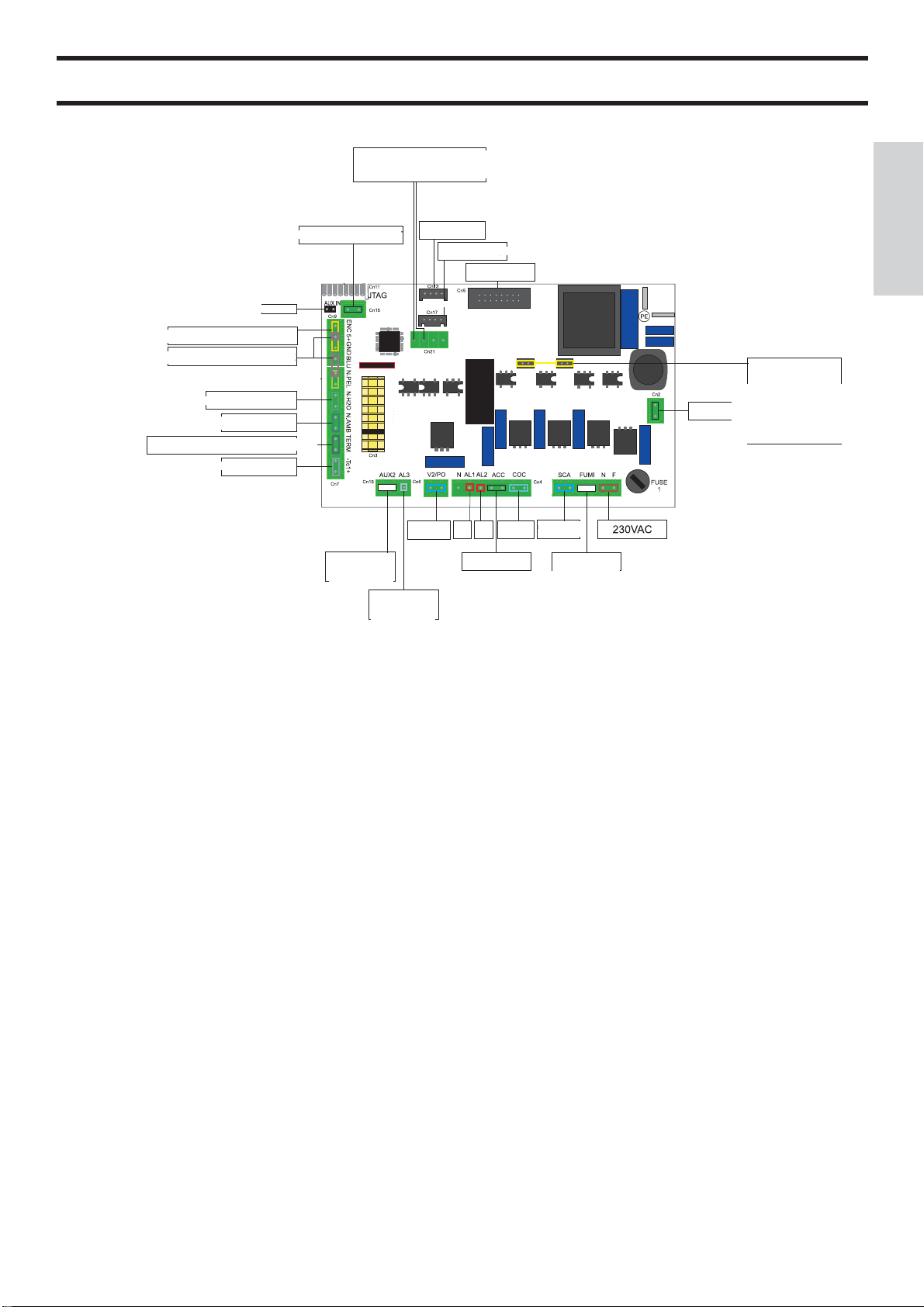
ELECTRONIC CIRCUIT BOARD
CONSOLE AND ACCESSORIES
ADD-line carrier
SMOKE VENT. ENCODER
PRESSURE TRANSDUCER
NTC 300°C PROBE
ENV. PROBE
ANCILLARY THERMOSTAT
*
SMOKE PROBE
SENSOR LEVEL PELLET
INLETS
CONTACT
SECURITY
SCREW
ENTRY
SECURITY
SCREW
BACKUP
BATTERY
EXCHANGER
2
SERIAL
VOLUME METER
DISPLAY
ALLARM
ALLARM
1
2
PLUG
SCREW
EXCHANGER
1
SMOKE
VENTILATOR
EXCHANGER
3
ENGLISH
FAN CONTROL
BOARDS
SAFETY DEVICES
THERMOCOUPLE:
placed at the smoke outlet to detect the temperature. Turns the
stove on and off and controls its operation based on defi ned
parameters.
AIR FLOW SENSOR:
placed in the air inlet channel. This intervenes if an anomaly
is detected in the combustion air fl ow and causes insuffi cient
circulation in the smoke ducts.
SAFETY THERMOSTAT:
trips when the temperature inside the stove is too high.
It stops pellet loading, causing the stove to go out
(see alarm A09 on pg. 29).
REMOTE IGNITION
On the circuit board, there is an input)
supplementary thermostat clean contact *) that can be used for
remote ignitions via external thermostats.
These devices must be installed by authorized CAT via an
optional cable, code 640560.
BACKUP BATTERY
A backup battery is found on the control board (3-Volt CR
2032 battery).
For more detailed information, please contact the DEALER
who has performed the fi rst 1st ignition.
- 27 -

MAINTENANCE
Before performing any maintenance, disconnect the appliance from the mains.
FAILURE TO PERFORM REGULAR MAINTENANCE, at least on a SEASONALbasis, could lead to poor functionality.
Any problems resulting from lack of maintenance will immediately void the warranty.
DAILY MAINTENANCE
Operations must be performed when the stove is off, cold and unplugged from the power supply
Cleaning must be carried out with a vacuum cleaner. (pg. 31)
ENGLISH
The whole procedure takes up a few minutes every day.
- Open the door, vacuum the hearth, vacuum the space around the combustion chamber where ash falls
(there is NO extractable ash pan).
- Remove the combustion chamber or clean it with a scraper, and unblock any blocked holes on all sides.
- Vacuum clean the combustion chamber compartment, clean touching edges and replace the combustion chamber
- If necessary clean the glass (cold)
NEVER VACUUM HOT ASH, it can make the vacuum cleaner breakdown and puts the household rooms at risk of fi re
SEASONAL MAINTENANCE (implemented by the DEALER)
- General internal and external cleaning
- Carefully clean the heat exchange pipes
- Clean/check the exhaust pipes
- NEVER loosen the Allen screws inside the fi rebox: the loader will fall
- Carefully clean and descale the combustion chamber and corresponding compartment
- Clean fan and mechanically inspect the play and fastenings
- Clean smoke duct (replace gasket on the smoke outlet pipe)
- Clean smoke extractor fan compartment, clean fl ow sensor and check thermocouple
- Clean, inspect and descale ignition heating element compartment and change heating element
- Clean/check display-control panel
- Visually inspect electric cables, connections and power cord
- Clean pellet hopper and check screw feeder-gearmotor assembly play
- Change door seal
- Test screw feeder loading, ignition, operation for ten minutes and shutdown.
If the stove is used frequently, it is advisable to clean the smoke duct every 3 months.
REMEMBER TO VACUUM THE COMBUSTION CHAMBER BEFORE EACH IGNITION
Should ignition fail, DO NOT re-ignite until you have emptied the combustion chamber.
ATTENTION: DO NOT EMPTY THE RESIDUE
OUT INTO THE PELLET HOPPER.
- 28 -
ADVICE FOR POTENTIAL PROBLEMS
In the event of a problem, the stove automatically carries out the shut-down procedure and shows the reason for shutdown on the display (see the various alarms below).
Never remove the plug during the shutdown phase caused by stoppage.
If stoppage occurs, to restart the stove, allow the shutdown process to take place (15 minutes with fi nal beep) and then
press the button.
Reignite the stove only once you have verifi ed the cause of stoppage and RECLEANED/EMPTIED the combustion chamber.
POSSIBLE CAUSES OF STOPPAGE AND INSTRUCTIONS AND SOLUTIONS
A01 Stove does not ignite
(occurs when the smoke temperature during start-up does not exceed the minimum threshold)
• Combustion chamber dirty or too many pellets
• No more pellets
• Chimney fl ue obstructed
• Likely faulty electrical resistance
A03 insuffi cient draught
(occurs when the fl ow of combustion air falls below the minimum allowable threshold)
• Chimney fl ue obstructed
• Door open
• Combustion chamber clogged
• Debimeter (air fl ow sensor) dirty
• Door gasket needs replacing
A05 hot smoke
(occurs when the smoke temperature exceeds the established safe temperature)
• Chimney fl ue obstructed
• Incorrect installation
• Stove clogged
• Pellet load high, check pellet adjustment (CAT)
A06 No pellets
(occurs when the pellet supply is exhausted; the display fl ashes following a “beep” sound)
• No pellets remaining in the hopper
• Gear motor not working
• Pellet inlet channel/ feed screw obstructed
• Pellet load low, check pellet adjustment
ENGLISH
A07 smoke sensor broken (occurs when the stove no longer reads the sensor)
• Thermocouple broken
• Thermocouple disconnected
A08 black out (not a defect of the stove)
(occurs if there has been an interruption in power lasting more than 5 seconds)
The stove has a “black out” function.
In the event of a power black out lasting less than 5 seconds, the stove will restart and return to the last function prior to shutdown.
If the black out time exceeds 5 seconds, the stove’s “black out” alarm is triggered, with the resulting cooling phase.
Below is a list of the various possibilities:
Stove status before the black out
OFF OFF OFF
PRELOAD BLACK OUT BLACK OUT
IGNITION BLACK OUT BLACK OUT
START START STANDY-BY THEN REIGNITION
OPERATION OPERATION STANDY-BY THEN REIGNITION
FINAL CLEANING FINAL CLEANING FINAL CLEANING
STAND-BY STAND-BY STAND-BY
ALLARM ALLARM ALLARM
ALARM MEMORY ALARM MEMORY ALARM MEMORY
Interruption time less than PR
“black out delay”
Interruption time greater than PR
“ black out delay”
- 29 -

ADVICE FOR POTENTIAL PROBLEMS
A09 safety thermal
(occurs when the safety thermostat, located against with the hopper, is tripped by overheating of the pellet hopper; to reset press
the red button on the right side of the stove after removing the protective black cap).
• Excessive pellet load in combustion chamber
• Stove/chimney fl ue dirty
A11 triac error
(occurs in the event of a board malfunction)
• Failure check carried out by technician
ENGLISH
• replace the circuit board
A12 smoke extractor malfunction
(occurs when the circuit board does not read the smoke extractor revs; call CAT)
• Smoke extractor blocked
• Speed sensor not working
• Smoke extractor not working
• Smoke motor thermostat intervention
• No earth connection
• faulty circuit board
- 30 -

CHECK LIST
To be integrated with a complete reading of the technical specifi cations
Positioning and installing
• Commissioned by a qualifi ed DEALER who has issued the warranty and maintenance manual
• Room ventilation
• Only the stove outlet passes through the smoke channel/chimney fl ue
• The smoke channel has: a maximum of 2 curves, a maximum 2 horizontal metres
• Chimney pot that is high enough to avoid downdraft areas
• The discharge pipes are made of a suitable material (stainless steel is recommended)
• When using any fl ammable materials (e.g. wood), all precautions have been taken to prevent a fi re hazard
Use
• Good quality, dry pellets are used
• The chimney pot and ash compartment are clean and well positioned
• The door is closed properly
• The combustion chamber is inserted properly into the relevant compartment
REMEMBER TO VACUUM THE COMBUSTION CHAMBER BEFORE EACH IGNITION
Should ignition fail, DO NOT re-ignite until you have emptied the combustion chamber.
OPTIONAL
ENGLISH
REMOTE CONTROL (optional- code 658830)
CLEANING ACCESSORIES
GlassKamin
(code 155240)
Used for cleaning
the ceramic glass
Ash vacuum cleaner
without motor
(code 275400)
Used for cleaning
the hearth
INFORMATION FOR USERS
In accordance with Art. 13 of the Legislative Decree No. 151, dated 25 July 2005, “Implementation of Directives:
2002/95/EC, 2002/96/EC and 2003/108/EC, pertaining to the reduction of hazardous substances used in electrical and
electronic equipment, as well as disposal of waste”.
The crossed-out wheeled bin symbol shown on the equipment or on the packaging indicates that the product must be disposed
of separately at the end of its useful life.
Therefore, at the end of the equipment’s useful life, the user must hand in the equipment to suitable collection facilities for
electrical and electronic waste, or return it to the retailer when a new, equivalent appliance is purchased in a ratio of one to one.
- 31 -

Madame, Monsieur,
Nous vous remercions et nous vous félicitons d’avoir choisi notre produit. Avant de l’utiliser, nous vous demandons de
lire attentivement cette fi che, afi n de pouvoir profi ter au mieux et en toute sécurité de toutes ses prestations.
Pour tout autre renseignement ou besoin, contactez le REVENDEUR chez lequel vous avez effectué votre achat ou visitez
notre site internet www.edilkamin.com à la rubrique REVENDEUR.
NOTE
- Après avoir désemballé le poêle, assurez-vous que le contenu est intègre et complet (revêtement, télécommande avec
écran, poignée “main froide”, livret de garantie, gant, fi che technique, spatule, sels déshumidifi ants, clé à 6 pans).
En cas d’anomalies, adressezvous tout de suite au revendeur chez lequel vous avez effectué l’achat et remettez-lui une
copie du livret de garantie et de la facture.
- Mise en service/test
Elle doit absolument être effectuée par le - REVENDEUR sous peine de voir la garantie expirer. La mise en service
ainsi qu’elle est décrite dans par la norme UNI 10683 Rév. 2005 (Chap. “3.21”) consiste en une série d’opérations de
de contrôle effectuées lorsque l’insert est installé et qui ont pour but de vérifi er que le système fonctionne bien et qu’il
est en accord avec les règlementations.
FRANÇAIS
- Des installations incorrectes, des entretiens mal effectués, une utilisation impropre du produit, déchargent l’entreprise
productrice de tout dommage éventuel découlant de l’utilisation du produit.
- Le numéro du coupon de contrôle, nécessaire pour l’identifi cation le poêle, est indiqué:
- Sur le haut de l’emballage
- Sur le livret de garantie qui se trouve à l’intérieur du foyer
- Sur la plaquette appliquée à l’arrière de l’appareil;
Cette documentation ainsi que la facture doivent être conservées pour l’identifi cation, et les informations qu’elles contiennent
devront être communiquées à l’occasion d’éventuelles demandes de renseignements et elles devront être mises
à disposition pour une éventuelle intervention d’entretien;
- Les détails représentés sont indicatifs, du point de vue graphique et géométrique.
- 32 -

INFORMATIONS POUR LA SECURITE
Les poêles sont conçus pour chauffer, grâce à une combustion
automatique de pellet dans le foyer, la pièce dans laquelle ils
se trouvent par irradiation et par mouvement d’air qui sort des
grilles frontales, et les pièces voisines grâce au mouvement de
l’air canalisable par les raccords à l’arrière.
• Les seuls risques découlant de l’emploi des poêles sont liés à
un non respect de l’installation ou à un contact direct avec les
parties électriques en tension (internes) ou à un contact avec le
feu et les parties chaudes (vitre, tuyaux, sortie air chaud) ou à
l’introduction de substances étrangères.
• Utiliser uniquement du pellet de bois comme combustible.
• Si des composants ne fonctionnent pas les poêles sont
dotés de dispositifs de sécurité qui garantissent l’extinction,
qui doit se faire sans intervenir.
• Pour un bon fonctionnement le poêle doit être installé en
respectant ce qui est indiqué sur cette fi che et pendant le fon-
ctionnement la porte ne doit pas être ouverte : en effet la
combustion est gérée automatiquement et ne nécessite aucune
intervention.
• En aucun cas des substances étrangères doivent être introduites
dans le foyer ou dans le réservoir.
• Pour le nettoyage du conduit de fumées (segment de conduit
qui relie le raccord de sortie des fumées du poêle avec le conduit
de cheminée) il ne faut pas utiliser des produits infl ammables.
• S’assurer que les poêles sont posées et allumées par un revendeur
habilité Edilkamin selon les indications de cette fi che.
• Pendant le fonctionnement du poêle, les tuyaux d’évacuation
et la porte atteignent des températures élevées (ne pas
toucher sans le gant prévu à cet effet).
• Ne pas déposer d’objets non résistants à la chaleur tout près
du poêle.
• Ne JAMAIS utiliser de combustibles liquides pour allumer
le poêle ou raviver la braise.
• Ne pas obstruer les ouvertures d’aération dans la pièce d’installation,
ni les entrées d’air du poêle.
• Ne pas mouiller le poêle, ne pas s’approcher des parties
électriques avec les mains mouillées.
• Ne pas insérer de réductions sur les tuyaux d’évacuation
des fumées.
• Le poêle doit être installé dans des pièces adaptées à la
sécurité contre les incendies et dotées de tous les services
(alimentation et évacuations) dont l’appareil a besoin pour un
fonctionnement correct et sûr
ATTENTION:
FRANÇAIS
• Les parties du foyer et du réservoir doivent être uniquement
aspirées avec un aspirateur.
• La vitre peut être nettoyée AFROID avec un produit spécial
(ex. GlassKamin Edilkamin) et un chiffon.
• Ne pas nettoyer à chaud.
La societé EDILKAMIN S.p.A. ayant son siège légal à Via Vincenzo Monti 47 - 20123 Milan - Code Fiscal P.IVA 00192220192
Déclare sous sa propre responsabilité:
Le poêle à pellets indiqué ci-dessous est conforme au règlement
UE 305/2011 (CPR) et à la norme européenne harmonisée
EN 14785:2006
POÊLE À PELLETS, avec marque commerciale EDILKAMIN,
dénommé FLEXA
N° DE SÉRIE: Réf. Plaque des caractéristiques
Déclaration de performance (DoP - EK 057): Réf. Plaque des
caractéristiques
La société déclare également:
que les poêles à pellets de bois FLEXA est conforme aux critères
des directives européennes:
2006/95/CE – Directive Basse Tension
2004/108/CE – Directive Compatibilité Électromagnétique
• SI L’ALLUMAGE ÉCHOUE, NE PAS RÉPÉTER
L’ALLUMAGE AVANT D’AVOIR VIDÉ LE CREUSET.
• LE PELLET QUI A ÉTÉ ENLEVÉ DU CREUSET NE
DOIT PAS ÊTRE DÉPOSÉ DANS LE RÉSERVOIR.
EDILKAMIN S.p.a. décline toute responsabilité eu égard à tout
dysfonctionnement de l’appareil en cas de remplacement, de
montage et/ou de modifi cations qui ne seraient pas effectués par
des personnels EDILKAMIN sans l’autorisation préalable de la
société.
- 33 -

CARACTERISTIQUES
CARACTÉRISTIQUES TECHNIQUES
Puissance nominal 8,0 kW
Rendement puissance nominal 89,2 %
Émissions CO (13% O2) puissance nominal 0,07 %
992
99
FRANÇAIS
552
55
55
546
Masses des fumées puissance nominal 5,5 g/s
Puissance réduite 3,4 kW
Rendement puissance réduite 92,6 %
Émissions CO (13% O2) puissance réduite 0,028 %
Masses des fumées puissance réduite 2,9 g/s
Surchauffe fumées maximum 175 °C
Tirage minimum 12 / 5 Pa
Autonomie min/max 6 / 15 heures
Consommation combustible min/max 0,8 / 1,9 kg/h
Capacité réservoir 15 kg
Volume de chauffe * 210 m³
Poids avec emballage (acier/céramique) 169/187 kg
Diamètre conduit fumées (A mâle) 80 mm
Diamètre conduit prise air extérieur (B mâle) 40 mm
* Le volume de chauffe est calculé compte tenu de l’utilisation
de pellets avec un p.c.i. d’au moins 4300 kcal/kg et une isolation
de la maison conforme à la Loi 10/91, et modifi cations successi-
ves et une demande de chaleur de 33 kcal/m³ par heure.
* Il est important de tenir compte aussi de la position du poêle
dans la pièce.
315,2
31,5
18
10,5
181,5
55
546
7,5
74,9106,6
368
37
CARACTERISTIQUES ELECTRIQUES
Alimentation 230Vac +/- 10% 50 Hz
Interrupteur on/off oui
Puissance absorbée moyenne 150 W
Puissance absorbée à l’allumage 400 W
Frecuencia mando a distancia (optional) Infrarouges
Protection sur alimentation générale ** Fusible F4 AL, 250
Protection sur carte électronique Fusible F4 AL, 250
Les données reportées ci-dessus sont indicatives.
EDILKAMIN s.p.a. se réserve le droit de modifi er sans
préavises produits afi n d’en améliorer les prestations.
FUSIBLE
* sur la prise avec interrupteur située à l’arrière
du poêle, deux fusibles
sont insères, l’un est
fonctionnel et l’autre
est de réserve.
*
- 34 -
*

CARACTERISTIQUES
FONCTIONNEMENT
Le combustible (pellet) est prélevé du réservoir de stockage
(A) et, grâce à une vis sans fi n (B) activée par
un motoréducteur (C), il est transporté dans le creuset de
combustion (D).
L’allumage du pellet se fait grâce à de l’air chaud produit par
une résistance électrique (E) et aspiré dans le creuset par un
extracteur de fumées (M).
Les fumées produites par la combustion sont extraites du
foyer grâce à ce même ventilateur centrifuge (M), et expulsées
par le raccord (F) situé en bas à l’arrière du poêle.
Par le biais du ventilateur (G), l’air passe dans un interstice
surle dos du foyer, où il est chauffé, pour être ensuite évacué
àl’extérieur, à travers la grille frontale (I).
Le foyer se compose d’une structure interne en fonte et il est
fermé sur le devant par deux petits volets superposés.
- un petit volet externe en vitre céramique
- Un petit volet interne en verre céramique en contact avec le
feu.
Le réservoir à combustible est situé dans la partie haute dupoêle. Le remplissage du réservoir a lieu à travers le couvercle
placédans la partie postérieure du top.
La quantité de combustible et l’extraction des fumées/alimentation air comburant, sont réglées par une carte électronique
dotée d’un software avec système Galileo
combustion à rendement élevé et à basses émissions.
Le panneau synoptique (L) est installé sur le haut et il permet
de gérer et de visualiser toutes les phases de fonctionnement.
Les principales étapes peuvent aussi être gérées avec la télécommande fournie en option.
Le revêtement externe est disponible dans les couleurs et dansles matériaux suivants:
- céramique: blanc opaque, rouge
- tôle: cotés en aluminium gris et top en céramique grise
- pierre ollaire
afi n d’obtenir une
*
L
I
A
B
FRANÇAIS
D
E
C
F
M
N
G
*
GALILEO est un système de sécurité et de réglage de la combustion qui permet un fonctionnement optimal quelles que
soient les conditions.
GALILEO garantit un fonctionnement optimal grâce à un capteur qui mesure le fl ux d’air participant à la combustion. La
détection et l’optimisation conséquente des paramètres de combustion a lieu en continu, de manière à pouvoir corriger en temps
réel les éventuelles anomalies de fonctionnement.
Le système GALILEO obtient une combustion constante en
réglant automatiquement le tirage selon les caractéristiques du
conduit de cheminée (courbes, longueur, forme, diamètre etc..)
et les conditions environnementales (vent, humidité, pression
atmosphérique, installation en haute altitude etc..). Il est nécessaire que les normes d’installation soient respectées.
- 35 -

ASSEMBLAGE
REVÊTEMENT
4
1
5
N
N
5
1
Liste des éléments constituants (voir fi g. 1):
• n° 6 plaques latérales en céramique (1-2-3)
• top en céramique (4)
• n° 2 cotés postérieurs en aluminium (5)
• kit fi xation des plaques en céramique
Pour le montage procéder de la manière suivante :
2
FRANÇAIS
3
fi g. 1
fi g. 2
N
N
N
V
N
2
N
N
3
Z
5
- Soulever le top en fonte, dévisser les vis (V) et démonter les
deux cotés postérieurs en aluminium (5) en les décrochant des
pivots de fi xation (Z) situés sur la base en fonte (fi g.2).
- Appliquer les petites plaques (N) à l’arrière des céramiques
(1-2-3) en les fi xant dans les trous prévus avec les vis fournies
(fi g. 3). En raison de caractéristiques de production les cérami-
ques, qui sont collées, pourraient être légèrement différentes en
hauteur l’une par rapport à l’autre. Afi n de remédier à l’éven-
tuelle variation de hauteur, il est possible d’interposer des petits
bouchons en caoutchouc fournis qui ne nuisent en aucun cas à
l’esthétique du poêle.
Interposer, entre la base en fonte et la céramique inférieure (3),
les petits bouchons en caoutchouc et la garniture fournie, tandis
que entre les céramiques (3-2-1) interposer seulement les petits
bouchons en caoutchouc fournis.
-Approcher du coté chaque élément en céramique et faire
correspondre les rainures (L présentes à l’extrémité du bord
antérieur) avec le profi l vertical en tôle dentée de la structure
(M-fi g. 4).
- Fixer les céramiques avec les petites plaques appliquées à la
structure du poêle en utilisant les vis et les rondelles fournies
dans les trous prévus à cet effet (fi g. 5).
-Remonter les deux côtés postérieurs en aluminium (5).
-Placer le top en céramique (4) dans les fentes prévues à cet
effet (S-fi g. 6).
NB : Dans la version avec revêtement en tôle, le poêle est
livré déjà assemblé, sauf le top en céramique qui doit être
placé dans les fentes prévues à cet effet (S-fi g. 6).
fi g. 3
fi g. 4
N
M
L
L
- 36 -
fi g. 5
fi g. 6
N
4
S
S

INSTALLATION
MONTAGE ET INSTALLATION (Revendeur)
Pour ce qui n’est pas expressément indiqué, se reporter pour
chaque pays aux normes locales. En Italie se reporter à la
norme UNI 10683/2005, ainsi qu’aux éventuelles indications
régionales ou des ASL locales. En cas d’installation dans une
copropriété, demander l’avis préventif au gérant.
VERIFICATION DE COMPATIBILITE
AVEC D’AUTRES DISPOSITIFS
Le poêle NE doit PAS être dans la même pièce où se trouvent
des extracteurs, des appareils de chauffage de type B, et autres
appareils qui peuvent compromettre le bon fonctionnement.
VERIFICATION BRANCHEMENT
ELECTRIQUE
Le poêle est pourvu d’un câble d’alimentation électrique à
brancher à une prise de 230 V 50 Hz, de préférence avec interrupteur magnétothermique. Des variations de tension supérieures à 10% peuvent compromettre le poêle (s’il n’est pas déjà
prévu, prévoir un interrupteur différentiel adapté).
L’installation électrique doit être aux normes; érifi er en particu-
lier l’effi cacité du circuit de terre. La ligne d’alimentation doit
avoir une section adaptée à la puissance de l’appareil. Le mauvais état de marche du circuit de terre provoque un mauvais
fonctionnement qu’Edilkamin ne peut prendre en charge.
(placer la fi che à un endroit accessible)
DISTANCES DE SÉCURITÉ POUR
ANTI-INCENDIE ET POSITIONNEMENT
Pour un fonctionnement correct, le poêle doit être positionné
perpendiculairement au sol.Vérifi er la capacité portante du sol.
Le poêle doit être installé dans le respect des conditions de
sécurité suivantes:
-distance minimum sur les côtés et sur le dos de 40 cm des
matériels moyennement infl ammables,
-ne placer aucun matériel facilement infl ammable devant le
poêle, à une distance inférieure à 80 cm,
-si le poêle est installé sur un sol infl ammable, intercaler une
plaque de matériel calorifuge dépassant d’au moins 20 cm des
côtés et 40 cm de la partie frontale.
En cas d’impossibilité de respecter les distances indiquées cidessus, mettre en place impérativement des mesures techniques
et demaçonnerie permettant d’éviter tout risque d’incendie.En
cas de connexion avec une paroi en bois ou d’un autre matériel
infl ammable, calorifuger le tuyau d’évacuation des fumées
avec de la fi bre de céramique ou avec un autre matériau présen-
tant les mêmes caractéristiques.
EVACUATION DES FUMEES
Le système d’évacuation doit être unique pour le poêle (des
conduits d’évacuation dans un conduit de cheminée commun
à d’autres dispositifs n’est pas acceptable). L’évacuation des
fumées se fait par le tuyau de 8 cm de diamètre situé à l’arrière.
Prévoir un raccord en T avec un bouchon de collecte de la vapeur de condensation au début du segment vertical.
Le conduit d’évacuation des fumées doit être relié avec l’extérieur en utilisant des tuyaux en acier ou noirs certifi és EN
1856. Le tuyau doit être scellé hermétiquement. Pour l’étanchéité des tuyaux et leur isolation éventuelle il faut utiliser des
matériaux aux températures élevées (silicone ou mastics pour
températures élevées). Les segments horizontaux peuvent avoir
une longueur jusqu’à 2 m. On peut avoir jusqu’à deux coudes
avec une amplitude maximum de 90°. Il est nécessaire (si le
tuyau d’évacuation ne s’insère pas dans un conduit de cheminée) d’avoir un segment vertical et un terminal contre le vent
(référence UNI 10683/2005). Le conduit vertical peut être interne ou externe. Si le conduit de fumées est à l’extérieur il doit
être calorifugé de manière adéquate. Si le conduit de fumées
s’insère dans un conduit de cheminée, celui-ci doit être autorisé pour les combustibles solides et s’il fait plus de 150 mm
de diamètre, il faut l’assainir en le tubant avec des tuyaux de
section et de matériaux adaptés (ex. acier 80 mm de diamètre).
Tous les segments du conduit de fumées doivent pouvoir être
inspectés. Les cheminées et les conduits de fumée auxquels
sont reliés les appareils qui utilisent des combustibles solides
doivent être nettoyés une fois par an (vérifi er s’il existe dans
son pays une règlementation à ce sujet). Si on omet de contrôler
et de nettoyer régulièrement on augmente la probabilité d’un
incendie de la cheminée.
Les installations possibles sont celles proposées aux
fi gures 1 et 2
CAS TYPIQUES
fi g. 1
fi g. 2
FRANÇAIS
PRISE D’AIR
Le local où se trouve le poêle doit impérativement avoir une
prise d’air d’une section d’au moins 80 cm², garantissant lerétablissement de l’air consommé par combustion.
Dans l’alternative, l’air pour le poêle pourra être prélevé directement de l’extérieur à travers le prolongement en acier du
tuyau de4cm de diamètre. Dans ce cas, des problèmes de condensation pourraient se présenter et il faudra protéger l’entrée
de l’air avec unfi let, dont une section libre d’au moins 12 cm²
devra être garantie. Le tuyau doit avoir une longueur inférieure à 1 mètre et il ne doit présenter aucun coude.Le tuyau doit
terminer avec segment à 90° degrés vers le bas ou avec une
protection contrer le vent.
En tout cas, tous les conduits d’admission d’air doit être ainsi
section libre d’au moins 12 cm² doit être garantie.
Le terminal externe du conduit de prise d’air doit être protégé
par un grillage contre les insectes qui toutefois ne doit pas
réduire la section passante utile de 12 cm².
A: conduit de cheminée en acier calorifugé
B: hauteur minimum 1,5 m
C-E: prise d’aire de la pièce (section passante de
80 cm² minimum
D: conduit de cheminée en acier, à l’intérieur du conduit
de cheminée existant dans le mur
CHEMINEE
Les caractéristiques fondamentales sont:
- section interne à la base égale à celle du conduit de cheminée
- section de sortie non inférieure au double de celle du conduit de
cheminée
- position en plein vent, au-dessus du toit et en-dehors des
zones de refl ux.
- 37 -

INSTRUCTIONS D’UTILISATION
Avant d’allumer.
Pour le 1er allumage il est indispensable de s’adresser à son
revendeur, qui étalonnera le poêle selon le type de pellet et les
conditions d’installation et activera ainsi la garantie.
Pendant les premiers allumages de légères odeurs de peinture
peuvent se dégager et elles disparaitront en peu de temps.
Avant d’allumer il est nécessaire de vérifi er :
==> L’installation correcte
==> L’alimentation électrique
==> La fermeture de la porte, qui doit être étanche
==> Le nettoyage du creuset
FRANÇAIS
==> La présence sur le display de l’indication de stand-by
(horaire et température).
Réglage volet externe
Enlever le grille supérieure fi xée avec baïonnette et ajuster
l’alignement du volet externe avec les cotés en céramique ou en
aluminium en agissant sur les vis V (fi g. 1).
fi g. 1
V
fi g. 2
Chargement du pellet dans le réservoir
Pour accéder au réservoir soulever le top en fonte (fi g. 2).
ATTENTION : utiliser le gant spécial fourni si on
charge le poêle pendant qu’il fonctionne et qu’il est
donc chaud.
NOTE sur le combustible
FLEXA est conçu et programmées pour bruler du pellet.
Le pellet est un combustible qui se présente sous forme de
petits cylindres, obtenus en comprimant de la sciure, à des
valeurs élevées, sans utilisation de liants ou autres matériaux
étrangers. Il est commercialisé dans des sacs de 15 kg.
Pour NE PAS compromettre le fonctionnement des poêles il
est indispensable de NE PAS bruler autre chose.
L’emploi d’autres matériaux (bois compris), qui peut être
relevé avec des analyses en laboratoire, entraine l’expiration de
la garantie.
Edilkamin a conçu, testé et programmé ses produits afi n qu’ils
garantissent les meilleures prestations avec du pellet aux
caractéristiques suivantes :
diamètre : 6 mm ;
longueur maximum : 40 mm ;
humidité maximum : 8% ;
rendement calorifi que : 4300 kcal/kg au moins
L’utilisation de pellets avec des caractéristiques différentes
implique la nécessité d’un nouvel étalonnage des poêles,
analogue à celui que fait le revendeur au 1er allumage. L’utilisation de pellets non adaptés peut provoquer : diminution
du rendement ; anomalies de fonctionnement ; blocages par
obstruction, saleté sur la vitre, non brulés...
Une simple analyse du pellet peut être faite visuellement :
Bonne qualité: lisse, longueur régulière, peu poudreux.
Mauvaise qualité: fentes longitudinales et transversales, très
poudreux, longueur très variable et avec présence de corps
étrangers.
- 38 -

INSTRUCTIONS D’UTILISATION
LE FONCTIONNEMENT
Le poêle a deux modes de fonctionnement:
-MANUEL :
En mode de fonctionnement MANUEL on règle la puissance à
laquelle on va faire travailler le poêle, indépendamment de la
température de la pièce où il est installé.
Pour sélectionner le mode de fonctionnement MANUEL ap-
puyer sur la poignée gauche et régler la température ambiante
souhaitée (RÈGLE TEMPÉRATUR-AMBIANT) au-delà de 40
°C, en tournant la poignée ou en utilisant les touches +/-.
Sur l’écran, l’inscription « MAN » apparaitra.
Pour modifi er la puissance du poêle, appuyer puis tourner la
poignée de droite ou utiliser les touches +/-, et pour confi rmer
la puissance choisie appuyer à nouveau sur la poignée ou sur la
touche ON/OFF.
-AUTOMATIQUE
En mode de fonctionnement AUTOMATIQUE on peut régler
la température objectif dans la pièce où le poêle est installé.
Lorsque le poêle aura atteint la température ambiante souhaitée
(RÈGLE TEMPÉRATUR-AMBIANT), il commencera, de
manière autonome, à moduler et se mettra sur la puissance 1.
Pour changer la température ambiante souhaitée (RÈGLE
TEMPÉRATUR-AMBIANT) selon sa convenance, appuyer
sur la poignée de gauche et la tourner ou bien utiliser les touches +/-.
Pour confi rmer appuyer de nouveau sur cette poignée ou sur la
touche ON/OFF.
La ventilation dépend toujours de la puissance utilisée, et on ne
peut donc pas la modifi er.
Touche On/Off du panneau
Allume ou éteint le poêle.
A l’intérieur des menus, la touche On/Off sert à revenir au
menu précédent ou à sortir de la modalité.
Touche +/- du panneau
Augmente ou diminue les valeurs qui apparaissent dans les
différents modes de fonctionnement.
Touche « réserve » du panneau
Cette fonction sert à déterminer la quantité de pellet restante
à l’intérieur du réservoir. Cette fonction peut être activée ou désactivée en allant dans le menu utilisateur «variation réserve ».
En appuyant sur la touche « réserve », une valeur égale à 15 kg
par défaut sera additionnée.
Pour changer la valeur, entrer dans le menu utilisateur «
variation réserve » et appuyer sur les touches ‘+’ ou ‘-‘ pour
augmenter ou diminuer cette valeur de 5 kg au minimum
jusqu’à 15 kg au maximum (si on sélectionne une valeur de 5
kg, à chaque fois qu’on appuiera sur la touche « réserve » 5 kg
seront ajoutés).
En cas d’erreurs, il est possible de revenir en arrière en appuyant sur la touche ‘-’
Touche du panneau
Donne des informations sur l’état du poêle, en appuyant sur
cette touche à l’intérieur des menus on voit s’affi cher le menu/
paramètre précèdent.
poignée gauche
panneau
poignée droite
REMPLISSAGE DE LA VIS SANS FIN
(seulement si le poêle est resté complètement sans
pellet)
Pour charger la vis sans fi n il faut entrer dans le MENU UTILI-
SATEUR, à la rubrique « CHARGE INITIAL » et appuyer sur
la touche.
Cette opération doit être effectuée uniquement quand le poêle
est éteint et complètement froid.
ALLUMAGE
Allumage automatique
Lorsque le poêle est en stand-by (inscription « ÉTEINT » affi -
ché sur l’écran), appuyer pendant 2’’ sur la touche on/off pour
démarrer la procédure d’allumage et pour affi cher l’inscription
« ALLUMAGE-PRÉCHARGEMENT » (étape pendant laquelle la quantité de pellet nécessaire pour l’allumage est chargée)
puis « ALLUMAGE » (étape pendant laquelle la bougie est
allumée jusqu’au relèvement de la fl amme) et ensuite
« ALLUMAGE-ATTENTE FLAMME » (étape pendant
laquelle le poêle reste en attente de relever la fl amme).
Lorsque la fl amme a été relevée, la résistance électrique
s’éteint et l’inscription « STABILISATION » apparait (c’est le
moment où le poêle contrôle l’augmentation de la température
des fumées qui doit respecter une augmentation de 2 degrés
par minute, dans le cas contraire l’alarme le signale). Une fois
cette étape terminée, si tous les tests sont positifs, l’inscription
« TRAVAIL » apparait.
Cette procédure dure environ 15 minutes.
Extinction
Lorsque le poêle est en marche, appuyer pendant 2’’ sur la touche ON/OFF pour démarrer la procédure d’extinction (ventilateurs air en marche, motoréducteur éteint, extracteur fumées en
marche) VENTILATEURS AIR et le message « POÊLE EN
EXTINCTION » s’affi che. Cette procédure dure au moins 15
minutes.
Une fois ce délai passé, si le poêle présente une température
supérieure au seuil prévu pour l’extinction, la procédure continuera jusqu’à ce que le seuil soit atteint.
En cas de blocage du poêle voir les alarmes pages 14-15 ou
contacter votre Revendeur.
MENU UTILISATEUR
Un « MENU UTILISATEUR » se trouve à l’intérieur de
l’écran, et ses fonctions doivent être changées par le Revendeur.
FRANÇAIS
- 39 -

INSTRUCTIONS D’UTILISATION
RÉGLAGE HORAIRE ET DATE
Appuyer sur la touche “menu” et tourner la poignée gauche pour voir s’affi cher sur l’écran l’inscription “RÉGLAGE HORLO-
GE”. Appuyer à nouveau sur la touche « menu » et tourner la poignée gauche pour voir apparaitre consécutivement les données
suivantes : Jour de la semaine, heure, minutes, jour, mois, année, qui peuvent être modifi ées avec la poignée droite.
A chaque déclic de la poignée gauche la valeur sera confi rmée. Appuyer sur la touche ON/OFF ou sur la poignée même pour sortir
de la programmation.
EXEMPLE DE RÉGLAGE :
Rég. Horloge Jour mardi Rég. Horloge Heure 15 : Rég. Horloge Minutes :00
Rég. Horloge Jour 7 Rég. Horloge Mois 6 Rég. Horloge année 11
CHRONOTHERMOSTAT A PROGRAMMATION JOURNALIÈRE/HEBDOMADAIRE
Il y a 3 modalités de programmation (journalière, hebdomadaire, week-end), toutes indépendantes les unes des autres, ce qui permet ainsi de multiples combinaisons selon ses propres exigences (on peut régler les horaires avec 10 minutes d’écart).
Appuyer sur la touche « menu » pour affi cher l’inscription « SET CHRONO » sur l’écran, appuyer ensuite sur la touche « menu »
ou appuyer sur la poignée de droite pour accéder au « SET CHRONO » et voir s’affi cher l’inscription « HABILITE CHRONO »
sur l’écran (réglé sur OFF par défaut).
Pour affi cher les 3 modalités de programmation (journalière, hebdomadaire, week-end) tourner la poignée de gauche ou utiliser les
FRANÇAIS
touches.
Pour régler les allumages et les extinctions utiliser la poignée de gauche ou les touches.
Pour changer les horaires des allumages et des extinctions utiliser la poignée de droite ou les touches +/-.
Pour sortir de la programmation sélectionnée utiliser la touche ON/OFF.
Programmation Journalière :
Possibilité de 2 allumages/extinctions au cours de la journée répétés tous les jours :
Exemple :
start1 10:00 stop1 12:00 start2 18:00 stop2 22:00
Programmation Hebdomadaire :
Possibilité de 4 allumages/extinctions dans la journée en choisissant les jours de la semaine, exemple :
start1 06:00 stop1 08:00 start2 07:00 stop2 10:00 start3 19:00 stop3 22:00….
lundi on
mardi on
mercredi off
jeudi on
vendredi on
samedi off
dimanche off
Programmation Week-end :
Possibilité de 2 allumages/extinctions pendant le week-end :
Exemple : start1 week-end 07:00 stop1 week-end 11:30
Exemple: start2 week-end 14:20 stop2 week-end 23:50
Lorsque le chronothermostat est actif, une icone qui représente l’horloge sera visible à coté de l’horaire.
lundi off
mardi off
mercredi on
jeudi off
vendredi off
samedi off
dimanche off
lundi on
mardi on
mercredi on
jeudi on
vendredi on
samedi on
dimanche on
- 40 -

APPAREILS ÉLECTRONIQUES
TÉLÉCOMMANDE cod. 658830 - optional
LÉGENDE SYMBOLES
N.B.: selon les lots de production, deux symboles différents pourront être utilisés pour la touche puissance (X-voir fi g. 1-2)
: touche allumage/extinction
+ : touche pour augmenter la puissance/température de travail
- : touche pour diminuer la puissance/température de travail
A : “TEMP. AMBIANTE”; change la température ambiante souhaitée (SET TEMP. AMBIANTE)
P (fi g. 1) M (fi g. 2) : touche “PUISSANCE”; change la puissance (de P1 à P5)
- la télécommande transmet avec un signal infrarouge, le led de transmission du signal doit être en ligne visuellement avec le led
de réception du poêle pour qu’il y ait une transmission correcte, donc dans un champ libre sans obstacles on a une distance couverte de 4-5mt.
-La télécommande fonctionne avec une pile alcaline de 3V, la durée de la pile dépend de l’utilisation mais couvre quand même
largement l’utilisation de l’utilisateur moyen pour toute une saison.
Pour remplacer la pile, enlever le couvercle Y où elle est logée.
La pile usagée doit être éliminée de manière opportune selon les règlementations en vigueur.
- la télécommande doit être nettoyée avec un chiffon humide sans vaporiser de produits détergents ou des liquides dessus, dans
tous les cas utiliser des détergents neutres sans substances agressives.
- manipuler la télécommande avec soin, vu son poids elle pourrait se casser lors d’une chute accidentelle.
FRANÇAIS
(X)
fi g. 1 fi g. 2
Y Y
NOTES :
-Température de travail : 0-40°C
-Température de stockage : -10/+50°C
-Humidité de travail : 20-90% H.R. sans condensation
-Degré de protection : IP 40
-Poids avec pile : 15 gr
(X)
- 41 -

APPAREILS ÉLECTRONIQUES
CARTE ÉLECTRONIQUE
CONSOLE ET ACCESSOIRES
ADD-line porteuse
FRANÇAIS
*
CAPTEUR DE NIVEAU PELLET
ENTRÉES
ENCODEUR VENT. FUMÉES
CAPTEUR DE PRESSION
SONDE NTC 300 C°
SONDE AMB.
THERMOSTAT SUPPLÉMENTAIRE
SONDE FUMÉES
VIS DE
SÉCURITÉ
CONTACT
BATTERIE
TAMPON
ÉCHANGEUR
2
VIS de sécurité
d’entrée
SÉRIE
DÉBITMÈTRE
AFFICHEUR
ALARME
ALARME
2
1
BOUGIE
Vis sans
fi n
ÉCHANGEUR
1
VENTILATEUR
FUMÉES
230VCA
ÉCHANGEUR
3
CONSEILS DE
CONTROLE
RAPIDE
DISPOSITIFS DE SECURITE
THERMOCOUPLE:
situé sur l’évacuation des fumées, il lit leur température. En
fonction des paramètres établis il contrôle les phases d’allumage, de travail et d’extinction.
CAPTEUR FLUX D’AIR:
situé sur le tuyau d’aspiration, il intervient quand le fl ux de
l’air comburant n’est pas correct, et provoque donc des problèmes de dépression dans le circuit des fumées.
THERMOSTAT DE SECURITE:
il intervient si la température à l’intérieur du poêle est trop
élevée.
Il bloque le chargement du pellet en provoquant l’extinction
du poêle. (voir alarme A09 page 44).
ALLUMAGES A DISTANCE
Une entrée (contact propre thermostat supplémentaire *) est
présente dans la carte électronique, elle peut être utilisée pour
les allumages à distance par l’intermédiaire de thermostats
externes.
L’installation de ces dispositifs doit être effectuée par des Revendeurs autorisés via un câble optionnel code 640560.
BATTERIE TAMPON
Une batterie tampon (type CR 2032 de 3 Volts) se trouve sur la
carte électronique.
Pour plus de références le cas échéant, contacter le Revendeur
qui a effectué le 1er allumage.
- 42 -

ENTRETIEN
Avant d’effectuer toute manutention, débrancher l’appareil du réseau d’alimentation électrique.
L’ABSENCE D’ENTRETIEN au moins SAISONNIER peut provoquer un mauvais fonctionnement.
D’éventuels problèmes dus à l’absence d’entretien entraineront l’expiration de la garantie.
ENTRETIEN QUOTIDIEN
Opérations à effectuer quand le poêle est éteint, froid et débranché du réseau électrique.
Le nettoyage doit être effectué en s’aidant d’un aspirateur (pag 46).
Toute la procédure ne demande que quelques minutes par jour.
- Aspirer la porte, aspirer le plan du feu, aspirer le siège autour du creuset où tombent les cendres
(IL N’Y A PAS de tiroir à cendres extractible).
- Retirer le creuset ou le décaper à l’aide d’une spatule, nettoyer les trous éventuellement bouchés sur tous les côtés.
- Aspirer le siège du creuset, nettoyer les bords de contact, remettre en place le creuset.
- S’il y a lieu, nettoyer le verre (à froid).
NE JAMAIS ASPIRER LES CENDRES CHAUDES, car cela compromet l’aspirateur utilisé et il y a un risque d’incendie
des pièces de la maison.
ENTRETIEN SAISONNIER (par le revendeur)
- Nettoyage général interne et externe.
- Nettoyage soigneux des tuyaux d’échange.
- Nettoyage/contrôle des tuyaux d’évacuation.
- NE JAMAIS desserrer les vis à tête hexagonale à l’intérieur du foyer, sous risque de faire tomber le chargeur
- Nettoyage soigneux et décapage du creuset et de son siège correspondant
- Nettoyage des ventilateurs, vérifi cation mécanique des jeux et des fi xations
- Nettoyage du canal de fumée (remplacement du joint)
- Nettoyage, inspection et détartrage du siège de la résistance d’allumage, éventuel remplacement de cette résistance
- Nettoyage /contrôle du Tableau synoptique
- Inspection visuelle des câbles électriques, des connexions et du cordon d’alimentation
- Nettoyage du réservoir à pellets et vérifi cation des jeux et de la vis sans fi n-motoréducteur
- Remplacement du joint de la porte
- Essai fonctionnel, chargement vis sans fi n, allumage, fonctionnement pendant 10 minutes et extinction
FRANÇAIS
Si vous utilisez très fréquemment le poêle, il est conseillé de nettoyer le conduit de fumées tous les 3 mois.
SE RAPPELER D’ASPIRER LE CREUSET AVANT CHAQUE ALLUMAGE
Si l’allumage échoue, NE PAS répéter l’allumage avant d’avoir vidé le creuset.
ATTENTION : NE PAS DÉCHARGER LES RÉSIDUS DANS LE TIROIR DU PELLET.
- 43 -

CONSEILS POUR ÉVENTUELS INCONVÉNIENTS
En cas de problèmes le poêle s’arrête automatiquement en effectuant l’opération d’extinction et l’écran affi che une in-
scription concernant les raisons de l’extinction (voir ci-dessous les différentes signalisations).
Ne jamais débrancher la fi che pendant la phase d’extinction due à un blocage.
Si un blocage se produit, pour redémarrer le poêle il faut laisser se dérouler la procédure d’extinction (15 minutes avec
retour sonore) puis appuyer sur la touche on/off.
Ne pas rallumer le poêle avant d’avoir vérifi é la cause du blocage et NETTOYÉ/VIDÉ le creuset.
SIGNALISATIONS D’ÉVENTUELLES CAUSES DE BLOCAGE, INDICATIONS ET RÉSOLUTIONS :
A01absence d’allumage
(se produit lorsque, pendant la phase d’allumage, la température des fumées ne dépasse pas le seuil minimum)
• Creuset sale ou trop de pellet
• Le pellet est épuisé
• Le conduit de cheminée est obstrué
• Résistance électrique probablement en panne
FRANÇAIS
A03 tirage insuffi sant
(se produit lorsque le fl ux de l’air comburant descend sous le seuil minimum consenti)
• Le conduit de cheminée est obstrué
• Porte ouverte
• Creuset bouché
• Débitmètre (capteur de fl ux d’air) sale
• Garniture de la porte à remplacer
A05 fumées chaudes
(se produit lorsque la température des fumées dépasse une température de sécurité)
• Le conduit de cheminée est obstrué
• Installation incorrecte
• Poêle bouché
• Chargement de pellet élevé, contrôler le réglage du pellet (Revendeur)
A06 absence de pellet
(se produit lorsque le pellet est épuisé ; l’écran clignote précédé par un « bip » sonore)
• Pellet épuisé dans le réservoir
• Motoréducteur en panne
• Conduit/vis sans fi n pellet bouché
• Chargement de pellet faible, contrôler le réglage du pellet.
A07 sonde fumées cassée (se produit lorsque le poêle ne lit plus la sonde)
• Thermocouple cassé
• Thermocouple débranché
A08 coupure d’électricité (ce n’est pas un défaut du poêle)
(se produit s’il y a eu une absence de tension dans le réseau électrique pendant plus de 5 secondes)
Le poêle possède une fonction de « black out ».
En cas d’interruption de l’énergie électrique, d’une durée inférieure à 5 secondes, le poêle se rallumera et reviendra à la fonction
précédant l’extinction. Si l’interruption est supérieure à 5 secondes, le poêle se mettra en alarme « black out », qui se traduit par
une phase de refroidissement.
Ci-dessous une liste des différentes possibilités :
État du poêle avant la coupure d’électricité
OFF OFF OFF
Tempo interruzione inferiore
PR “ritardo black out”
Tempo interruzione superiore
PR “ritardo black out”
PRÉCHARGE BLACK OUT BLACK OUT
ALLUMAGE BLACK OUT BLACK OUT
DÉMARRAGE DÉMARRAGE STAND-BY PUIS RALLUMAGE
TRAVAIL TRAVAIL STAND-BY PUIS RALLUMAGE
NETTOYAGE FINAL NETTOYAGE FINAL NETTOYAGE FINAL
STAND-BY STAND-BY STAND-BY
ALARME ALARME ALARME
MÉMOIRE ALARME MÉMOIRE ALARME MÉMOIRE ALARME
- 44 -

CONSEILS POUR ÉVENTUELS INCONVÉNIENTS
A09 sécurité thermique
(se produit lorsque le thermostat de sécurité, situé au contact du réservoir, se déclenche à cause d’une surchauffe du réservoir à
pellet ; pour réarmer appuyer sur le bouton rouge sur le coté droit du poêle après avoir enlevé le capuchon noir de protection).
• Chargement excessif de pellet dans le creuset
• Poêle/conduit de cheminée sale
A011 erreur triac
(se produit lorsque la carte est en panne)
• Vérifi cation de la panne par le technicien
• Remplacement de la carte électronique
A012 panne extracteur
(se produit lorsque la carte électronique ne lit pas les tours de l’extracteur de fumées ; appeler le revendeur)
• Extracteur de fumées bloqué
• Capteur de tours en panne
• Extracteur de fumées en panne
• Intervention thermostat moteur fumées
• Absence de mise à la terre
• Carte électronique défectueuse
FRANÇAIS
- 45 -

CHECK LIST
A intégrer avec la lecture complète de la fi che technique
Pose et installation
• Mise en service effectuée par le revendeur habilité qui délivrer la garantie et le livret de maintenance
• Aération dans la pièce
• Le conduit de fumées/conduit de cheminée reçoit seulement l’évacuation du poêle
• Le conduit de fumées présente : maximum 2 courbes
maximum 2 mètres en horizontal
• cheminée au-delà de la zone de refl ux
• Les tuyaux d’évacuation sont en matériau adéquat (conseillé acier inox)
• En cas de traversée d’éventuels matériaux infl ammables (ex. bois) toutes les précautions ont été prises pour •
• éviter des incendies.
Utilisation
• Le pellet utilisé est de bonne qualité et non humide.
• Le creuset et la niche cendres sont propres et bien positionnés.
• La porte est bien fermée.
FRANÇAIS
• Le creuset est bien inséré dans sa niche
SE RAPPELER D’ASPIRER LE CREUSET AVANT CHAQUE ALLUMAGE
Si l’allumage échoue, NE PAS répéter l’allumage avant d’avoir vidé le creuset.
OPTIONS
TÉLÉCOMMANDE (optional- code 658830)
ACCESSOIRES POUR LE NETTOYAGE
Glasskamin
(code 155240)
Utile pour le nettoyage
de la vitre céramique
Bidon pour aspirer les
cendres sans moteur
(code 275400)
Utile pour le
nettoyage du foyer
INFORMATIONS POUR LES UTILISATEURS
Suivant l’art.13 du décret législatif 25 juillet 2005, n.151 “Mise en oeuvre des Directives 2002/95/CE,2002/96/CE et
2003/108/CE, concernant la réduction de l’utilisation de substances dangereuses dans les appareils électriques et électroniques, ainsi que le traitement des déchets”.
Le symbole du conteneur barré reporté sur l’appareil ou sur la boite indique que quand le produit arrive en fi n de vie utile il
doit être traité séparément des autres déchets.
L’utilisateur devra donc donner l’appareil arrivé en fi n de vie aux centres spécialisés de collecte sélective des déchets élec-
troniques et électrotechniques, ou bien le rapporter au revendeur au moment de l’achat d’un nouvel appareil de type équivalent, à raison de un par un.
- 46 -

Estimado Sr./Sra.
Le agradecemos y le felicitamos por haber elegido un producto nuestro. Antes de utilizarlo, le pedimos que lea atentamente
esta fi cha con el fi n de poder disfrutar de manera óptima y con total seguridad de todas sus características.
Para más aclaraciones o en caso de necesidad diríjase a su DISTRIBUIDORE donde ha efectuado la compra o visite
nuestro sitio internet www.edilkamin.com en la opción DISTRIBUIDORE.
NOTA
- Después de haber desembalado la estufa, asegúrese de que el aparato esté íntegro y completo (revestimiento, mando a
distancia con pantalla, manija “manofría”, libro de garantía, guante, fi cha técnica, espátula, sales deshumidifi cadoras,
llave Allen)
En caso de anomalías contacte rápidamente el distribuidore donde lo ha comprado al que entregará copia del libro de
garantía y del documento fi scal de compra.
- Puesta en servico/ensayo
Deberá ser efectuada absolutamente por el DISTRIBUIDORE de lo contrario decaerá la garantía. La puesta en servicio
como lo describe por la norma UNI 10683 Rev. 2005, (capítulo “3.21”) consiste en una serie de operaciones de control
con el insertable instalado y con el objetivo de asegurar el funcionamiento correcto del sistema y la conformidad del
mismo a las normativas.
- instalaciones incorrectas, mantenimientos realizados incorrectamente, el uso impropio del producto, exoneran a la
empresa fabricante de cualquier daño que deriva del uso.
- El número de cupón de control, necesario para la identifi cación de estufa, está indicado:
- en la parte alta del embalaje
- en el libro de garantía dentro del hogar
- en la placa aplicada en la parte posterior del aparato;
ESPAÑOL
Dicha documentación debe ser conservada para la identifi cación junto con el documento fi scal de compra cuyos datos
deberán comunicarse en ocasión de posibles solicitudes de informaciones y puestos a disposición en caso de posible
intervención de mantenimiento;
- las piezas representadas son gráfi ca y geométricamente indicativas.
- 47 -

INFORMACIONES DE SEGURIDAD
Las estufas están proyectadas para calentar, a través de una
combustión automática de pellet en el hogar, el local en el cual
se encuentran por radiación y por movimiento de aire que sale de
las rejillas frontales, los locales contiguos por medio del movimiento del aire canalizable por las bocas en la parte posterior.
• Los únicos riesgos que derivan del uso de las estufas están
relacionados con el incumplimiento de l instalación o con un
contacto directo con partes eléctricas en tensión (internas), o con
un contacto con fuego y partes calientes (vidrio, tubos, salida de
aire caliente) o con la introducción de sustancias extrañas.
• Usar como combustible solo pellet de leña.
• Si no funcionasen los componentes, las estufas están dotadas
de dispositivos de seguridad que garantizan su apagado, que se
efectuará sin intervenir en ningún momento. Para un funcionamiento regular la estufa ha de ser instalada respetando lo indicado en esta fi cha y durante su funcionamiento la puerta no deberá
abrirse: de hecho la combustión es controlada automáticamente y
no necesita ninguna intervención.
• En ningún caso han de introducirse en el hogar o en el depósito
sustancias extrañas. • Para la limpieza del canal de humo (tramo
de tubo que conecta la boca de salida de humos de la estufa con
el tubo de humos) no deben utilizarse productos infl amables.
• Las partes del hogar y del depósito han de aspirarse exclusiva-
ESPAÑOL
mente con aspirador.
• El cristal puede limpiarse en FRÍO con el producto adecuado
(por ej. GlassKamin Edilkamin) y un paño.
• No limpie en caliente.
• Asegurarse que las estufas sean colocadas y encendidas por el
Distribuidore habilitado Edilkamin según las indicaciones de la
presente fi cha.
• Durante el funcionamiento de la estufa, los tubos de descarga
y la puerta alcanzan altas temperaturas (no toque sin el guante
apropiado).
• No deposite objetos no resistentes al calor cerca de la estufa
• No utilice NUNCA combustibles líquidos para encender la
estufa o para reavivar las brasas.
• No obstruya las aperturas de aireación del local de instalación,
ni las entradas de aire de la misma estufa.
• No moje la estufa, no se acerque a las partes eléctricas con las
manos mojadas.
• No introduzca reducciones en los tubos de descarga de humos.
• La estufa debe ser instalada en locales adecuados para la
seguridad contra incendios y dotados de todos los servicios
(alimentación y descargas) que el aparato requiere para un
correcto y seguro funcionamiento.
ATENCIÓN
• EN CASO DE ENCENDIDO FALLIDO, NO REPETIR
EL ENCENDIDO ANTES DE HABER VACIADO EL
CRISOL.
•: EL PELLET VACIADO DEL CRISOL
NO DEBE COLOCARSE EN EL DEPÓSITO.
El abajo fi rmante EDILKAMIN S.p.A., con sede legal en Via
Vincenzo Monti 47 - 20123 Milán - NIF 00192220192
Declara bajo su propia responsabilidad que:
La estufa de pellet indicada cumple la Normativa UE 305/2011
(CPR) y la Norma Europea armonizada
EN 14785:2006
ESTUFA DE PELLET, de marca comercial EDILKAMIN, denominada FLEXA
N° de SERIE: Ref. Etiqueta datos
Declaración de prestación (DoP - EK 057): Ref. Etiqueta de
datos
Asimismo declara que:
la estufa de pellet de leña FLEXA respeta los requisitos de las
directivas europeas:
2006/95/CE – Directiva Baja Tensión
2004/108/CE – Directiva Compatibilidad Electromagnética
EDILKAMIN S.p.a. no se responsabiliza del mal funcionamiento
del aparato en caso de sustitución, montaje y/o modifi caciones
efectuadas por personal ajeno a EDILKAMIN sin autorización
de la bajo fi rmante.
- 48 -

CARACTERÍSTICAS
CARACTERÍSTICAS TÉCNICAS
Potencia nominal 8,0 kW
Rendimiento potencia nominal 89,2 %
Emisiones CO (13% O2) potencia nominal 0,07 %
992
99
552
55
55
546
Masa de humos potencia nominal 5,5 g/s
Potencia reducida 3,4 kW
Rendimiento potencia reducida 92,6 %
Emisiones CO (13% O2) potencia reducida 0,028 %
Masa de humos potencia reducida 2,9 g/s
Máximo exceso de temperatura humos 175 °C
Tiro minimo 12 / 5 Pa
Autonomía min/max 6 / 15 horas
Consumo combustibile min/max 0,8 / 1,9 kg/h
Capacidad depósito 15 kg
Volumen calentable* 210 m³
Peso con embalaje (acero/cerámica) 169/187 kg
Diámetro conducto humos (A macho) 80 mm
Diámetro conducto toma aire (B macho) 40 mm
* El volumen calentable se calcula considerando la utilización de
pellet con p.c.i. de al menos 4300 Kcal/Kg y un aislamiento de la
casa tal y como establece la L 10/91, y sucesivas modifi caciones
y una solicitación de calor de 33 Kcal/m³ hora
* Es importante tomar en consideración también la colocación
de la estufa en el ambiente a calentar.
ESPAÑOL
315,2
31,5
18
10,5
181,5
55
546
7,5
74,9106,6
368
37
CARACTERÍSTICAS ELÉCTRICAS
Alimentación 230Vac +/- 10% 50 Hz
Interruptor on/off sí
Potencia media absorbida 150 W
Potencia absorbida en el encendido 400 W
Frecuencia mando a distancia infrarrojos
Protección en alimentación general** Fusible F4 AL, 250
Protección en fi cha electrónica Fusible F4 AL, 250
Los datos indicados arriba son indicativos.
EDILKAMIN s.p.a. se reserva modifi car sin previo aviso los
productos para mejorar las prestaciones.
FUSIBLE
*en la toma con interruptor colocada detrás
de la estufa, hay introducidos dos fusibles, de
los cuales uno funciona
y el otro de reserva.
- 49 -
*
*

CARACTERÍSTICAS
FUNCIONAMIENTO
El combustible (pellet) se recoge del depósito de almacenaje
(A) y, a través de una cóclea (B) activada por un motorreductor
(C), se transporta en el crisol de combustión (D). El encendido del pellet se efectúa por medio de aire caliente producido
por una resistencia eléctrica (E) y aspirada en el crisol por un
extractores de humos (M), y se expulsan a través de la boca (F)
ubicada en la zona baja de la parte posterior de las estufas.
A través del ventilador (G) pasa aire en la cámara de aire detrás
del hogar, donde se calienta para luego salir al ambiente desde
la rejilla frontal (I).
El hogar está realizado con una estructura interna en fundición,
cerrada en la parte frontal por dos hojas sobrepuestas.
- una puerta externa de vidrio cerámico
- una puerta pequeña interna de vitrocerámica en contacto
con el fuego.
El depósito del combustible está ubicado en la parte alta de la
estufa.
La cantidad de combustible y la extracción de humos/alimentación aire comburente, se regulan por medio de la fi cha elec-
trónica dotada de software con sistema Galileo
obtener una combustión de alto rendimiento y bajas emisiones.
En la tapa está instalado el panel sinóptico (L) que permite la
gestión y la visualización de todas las fases de funcionamiento.
ESPAÑOL
Las principales fases pueden ser controladas también por medio del mando a distancia opcional.
El revestimiento externo está disponible en los siguientes
colores y materiales:
- cerámica: blanco opaco, roja
- chapa: lados de aluminio, gris y tapa de cerámica gris
- piedra ollar
con el fi n de
*
L
I
A
B
D
E
C
F
M
N
G
*
GALILEO es un sistema de seguridad y regulación de la combustión que permite un funcionamiento óptimo en cualquier condición.
GALILEO garantiza un funcionamiento excelente gracias a un
sensor que mide el fl ujo de aire que participa en la combustión.
La detección y la consiguiente optimización de los parámetros
de combustión tienen lugar continuamente a fi n de corregir en
tiempo real eventuales anomalías de funcionamiento.
El sistema GALILEO obtiene una combustión constante
regulando automáticamente el tiro según las características del
tubo de humos (curvas, longitud, forma, diámetro etc.) y las
condiciones ambientales (viento, humedad, presión atmosférica,
instalaciones en alta cota, etc.). Es necesario que se respeten las
normas de instalación.
- 50 -

ENSAMBLAJE
REVESTIMIENTO
4
1
5
N
N
5
1
Lista de las partes constituyentes (ver fi g. 1):
• 6 azulejos laterales de cerámica (1-2-3)
• tapa de cerámica (4)
• 2 lados posteriores de aluminio (5)
• kit de fi jación de azulejos de cerámica
Para el montaje proceder de la siguiente manera:
fi g. 1
fi g. 2
N
2
N
N
3
V
N
2
N
N
3
Z
5
- Levantar la tapa de fundición, afl ojar los tornillos (V) y
desmontar los dos lados posteriores de aluminio (5) desenganchándolos de los pernos de fi jación (Z) colocados en la base de
fundición fi g. 2.
- Aplicar por la parte trasera de las cerámicas (1-2-3) las placas
(N) fi jándolas en los orifi cios previstos por medio de los tornil-
los suministrados (fi g. 3).
Por características de producción las cerámicas, al estar realizadas en colada, pueden ser ligeramente diferentes en altura
la una de la otra. Para proveer a la posible variación de altura,
es posible interponer los tapones de goma sin perjudicar la
estética de la estufa.
Interponer entre la base de fundición y la cerámica inferior
(3) los tapones de goma y la empaquetadura suministrada, y
entre las cerámicas (3-2-1) interponer solo los tapones de goma
suministrados.
- Apoyar por el lado cada elemento de cerámica adaptando las
ranuras (L presentes en la extremidad del borde anterior) sobre
el perfi l vertical de chapa dentada de la estructura (M – fi g. 4).
- Fijar las cerámicas con las placas aplicadas, a la estructura de
la estufa utilizando los tornillos y las arandelas suministradas
en los orifi cios correspondientes (fi g. 5).
- Volver amontar los dos lados posteriores de aluminio (5)
- Colocar la tapa de cerámica (4) en las ranuras correspondientes (S-fi g. 6).
NB: En la versión con revestimiento de chapa, la estufa se
suministra ensamblada, excepto la tapa de cerámica que
debe ser colocada en las ranuras correspondientes (S fi g. 6).
ESPAÑOL
fi g. 3
fi g. 4
N
M
L
L
- 51 -
fi g. 5
fi g. 6
N
4
S
S

INSTALACIÓN
MONTAJE E INSTALACIÓN (DISTRIBUIDOR)
En lo no expresamente indicado, hágase referencia a las normativas locales en cada nación. En Italia hacer referencia a la
norma UNI 10683/2005, y a eventuales indicaciones regionales
o de las ASLlocales. En caso de instalación en comunidad de
propietarios, solicitar el visto bueno previo al administrador.
VERIFICACIÓN DE COMPATIBILIDAD
CON OTROS DISPOSITIVOS
La estufa NO debe encontrarse en el mismo ambiente donde
hay extractores, aparatos de calefacción de tipo B, y otros aparatos que puedan poner en peligro el correcto funcionamiento.
CONTROL CONEXIÓN ELÉCTRICA
(posicionar el enchufe en un punto accesible)
La estufa está dotada de un cable de alimentación eléctrica que
se conectará a una toma de 230V 50 Hz, preferiblemente con
interruptor magnetotérmico. Las variaciones de tensión superiores al 10% pueden estropear la estufa (si no existe hay que
prever un interruptor diferencial adecuado). El sistema eléctrico debe ser según norma de ley, comprobar de manera particular la efi ciencia del circuito de tierra. La línea de alimentación
debe tener una sección adecuada a la potencia del aparato.
La inefi ciencia del circuito de tierra provoca el mal
funcionamiento del cual Edilkamin no se hace responsable.
DISTANCIAS DE SEGURIDAD PARA
ANTI-INCENDIO Y POSICIONAMIENTO
ESPAÑOL
Para el correcto funcionamiento la estufa ha de ser colocada en
posición estándar.
Verifi car la capacidad portadora del suelo.
La estufa ha de ser instalada respetando las siguientes
condiciones de seguridad:
-distancia mínima en los lados y en la parte posterior de 40 cm
de los materiales medianamente infl amables
-delante de la estufa no pueden colocarse materiales fácilmente
infl amables a menos de 80 cm
-si la estufa está instalada encima de un suelo infl amable ha
de ser interpuesta una lámina de material aislante al calor que
sobresalga al menos 20 cm en los lados y 40 cm en frente.
Si no resultara posible prever las distancias arriba indicadas,
es necesario poner en marcha medidas técnicas y de obra para
evitar cualquier riesgo de incendio. En caso de conexión con
pared de madera o de otro material infl amable, es necesario
aislar el tubo de descarga de humos con fi bra cerámica u otro
material de iguales características.
DESCARGA DE HUMOS
El sistema de descarga de
humos debe ser único para la estufa (no se admiten descargas en
salida de humos común a otros dispositivos).
La descarga de humos se realiza desde el tubo de diámetro 8 cm
situado en la parte posterior.
Ha de preverse un T con tapón de recogida de condensaciones al
principio del tramo vertical.
La descarga de humos debe conectarse con el exterior utilizando
apropiados tubos de acero certifi cados EN 1856.
El tubo debe estar sellado herméticamente.
Para el cierre hermético de los tubos y su eventual aislamiento
es necesario utilizar materiales resistentes a altas temperaturas
(silicona o masilla de altas temperaturas).
El único tramo horizontal admitido puede tener un longitud
de hasta 2 m. Es posible un número de hasta dos curvas con
amplitud máx 90°. Es necesario (si la descarga no se introduce
en un tubo de salida de humos) un tramo vertical y un terminal
antiviento (referencia UNI 10683/2005).
El conducto vertical puede ser interior o exterior. Si el canal de
humo está en el exterior debe estar aislado adecuadamente.
Si el canal de humo se introduce en un tubo de salida de humos,
éste debe estar autorizado para combustibles sólidos y si tiene el
diámetro más grande de 150 mm es necesario sanearlo entubándolo con tubos de sección y materiales idóneos (por ej: acero 80
mm de diámetro).
Todos los tramos del conducto de humos deben ser accesibles.
Las chimeneas y los conductos de humo a lo que están conectados los aparatos que usan combustibles sólidos deben limpiarse
una vez al año (verifi car si en el propio país existe una normativa
al respecto). La ausencia de control y limpieza regulares aumenta
la probabilidad de un incendio de la chimenea.
Las posibles instalaciones resultan ser aquéllas propuestas en las
fi guras 1 y 2 .
CASOS TÍPICOS
fi g. 1
fi g. 2
TOMA DE AIRE
Es necesario que el local donde se coloca la estufa tenga una
toma de aire con una sección de al menos 80 cm2 que garantice
el cambio de aire consumado por la combustión.Como alternativa, es posible coger el aire para la estufa directamente del
exterior a través de una prolongación del tubo, en acero, y con
un diámetro de 4 cm. En este caso pueden existir problemas
de condensación y es necesario proteger con una red la entrada
de aire, garantizando una sección libre de al menos 12 cm². El
tubo tiene que tener un largo inferior a 1 metro y no tiene que
tener curvas.Tiene que acabar con un tramo de 90º hacia abajo
o con una protección para el viento.
En cualquier caso, todo el aire de manera conducto de admisión
debe ser garantizada una sección libre al menos de 12 cm².
El terminal externo del conducto toma de aire debe ser protegido con una red contra insectos que no reduzca la sección
pasante útil de 12 cm².
A:
tubo de salida de humos de acero aislado
B:
altura mínima 1,5m
C-E:
toma de aire del ambiente
(sección de conexión mínimo 80 cm²)
D:
tubo de salida de humos de acero, interno al tubo de salida
de humos existente de obra.
CHIMENEA
Las características fundamentales son:
- sección interna en la base igual que la del tubo de humos
- sección de salida no menor que el doble de la del tubo de
humos
- posición a todo viento, por encima del techo y fuera de las
zonas de refl ujo.
- 52 -

INSTRUCCIONES DE USO
Antes de encender.
Para el primer encendido es indispensable dirigirse al
Distribuidor de zona Edilkamin, que calibrará la estufa según
el tipo de pellet y condiciones de instalación activando de esta
forma la garantía.
Durante los primeros encendidos se pueden apreciar ligeros
olores a pintura que desaparecerán en breve tiempo.
Antes de encender es necesario comprobar:
==> La correcta instalación
==> La alimentación eléctrica.
==> El cierre de la puerta, que debe ser hermético.
==> La limpieza del crisol
==> La presencia en la pantalla de la indicación de estado
en espera (horario y temperatura).
Regulación puerta externa
Extraer la rejilla superior fi jada en bayoneta y regular el ali-
neamiento de la puerta externa con los lados de cerámica o de
aluminio trabajando en los tornillos V (fi g. 1).
fi g. 1
V
fi g. 2
ESPAÑOL
Carga del pellet en el depósito
Para acceder al depósito elevar la tapa de fundición (fi g. 2).
ATENCIÓN:
utilizar el guante apropiado suministrado si se carga la
estufa mientras está en funcionamiento y por lo tanto
caliente.
NOTA sobre el combustible.
FLEXA están proyectadas y programadas para quemar pellet
de madera de 6 mm de diámetro.
El pellet es un combustible que se presenta en forma de pequeños cilindros, obtenidos prensando serrín, de altos valores,
sin usar aglutinantes u otros materiales extraños.
Se comercializa en sacos de 15 Kg.
Para NO poner en peligro el funcionamiento de las estufas
es indispensable NO quemar otras cosas. La utilización de
otros materiales (incluida leña), detectable a través de análisis de laboratorio, dejaría sin efecto la garantía. EdilKamin
ha proyectado, probado y programado sus propios productos
para que garanticen las mejores prestaciones con pellet de las
siguientes características:
- diámetro: 6 milímetros
- longitud máxima: 40 mm
- humedad máxima: 8%
- rendimiento calórico: 4300 kcal/kg
El uso de pellet con diferentes características implica la
necesidad de un específi co ajuste de las estufas, análogo al
que realiza el DISTRIBUIDOR en el primer encendido.
El uso de pellet no apropiados puede provocar: disminución del rendimiento, anomalías de funcionamiento,
bloqueos por obstrucción, suciedad del vidrio, materiales
incombustos. Un simple análisis del pellet puede llevarse
a cabo visualmente.
Bueno: Liso, longitud regular, poco polvoroso.
De mala calidad: ccon grietas longitudinales y transver-
sales muy polvoroso, longitud muy variable y con presencia de cuerpos extraños.
- 53 -

INSTRUCCIONES DE USO
EL FUNCIONAMIENTO
La estufa tiene dos modalidades de funcionamiento:
- MANUAL:
En la modalidad de funcionamiento MANUAL se programa la
potencia en la que trabajará la estufa. Independientemente de la
temperatura de la habitación en la que está instalada.
Para seleccionar la modalidad de funcionamiento MANUAL
presionar la manivela izq. y programar la temperatura ambiente deseada (SET TEMPERATURA AMBIENTE) a más de
40 °C, mediante la rotación de la misma manivela o utilizando
las teclas +/-.
En la pantalla se visualizará la anotación “MAN”.
Presionando, y sucesivamente girando la manivela de la derecha o utilizando las teclas +/-, se modifi ca la potencia de la
estufa, volviendo a presionar la manivela o la tecla ON/OFF se
confi rma la potencia seleccionada.
- AUTOMÁTICA
En la modalidad de funcionamiento AUTOMÁTICA se puede
programar la temperatura objetivo en el local donde está instalada la estufa.
La estufa, autónomamente, cuando alcanza la temperatura
ambiente deseada (SET TEMPERATURA AMBIENTE), irá
en modulación llevándose en potencia 1.
ESPAÑOL
Presionando y girando la manivela de la izquierda o utilizando
las teclas +/- se cambia la temperatura ambiente deseada
(SET TEMPERATURA AMBIENTE) a su gusto.
Volviendo a presionar la misma manivela o la tecla ON/OFF
se confi rma.
La ventilación siempre corresponde con la potencia en uso, por
lo tanto no se puede cambiar.
Tecla On/Off del panel
Enciende o apaga la estufa.
En el interior de los menús la tecla On/Off sirve para volver al
menú precedente o salir de la modalidad.
Tecla +/- del panel
Aumenta o disminuye los valores que aparecen en las diferentes modalidades de funcionamiento
.
Tecla “reserva” del panel
Función que determina la cantidad de pellet residual en el
interior del depósito. Dicha función puede ser habilitada o
deshabilitada por medio del menú usuario “variación reserva”.
Presionando la tecla ‘reserva’, se sumará un valor equivalente a
15 Kg por defecto.
Se puede variar el valor, entrando en el menú usuario “variación reserva” y presionando las teclas ‘+’ o ‘-‘ se aumentará o
disminuirá este valor de un mínimo de 5 Kg hasta un máximo
de 15 Kg (programando un valor de 5 Kg, cada vez que se
presione la tecla ‘reserva’ se añadirán 5 chili).
En el caso de errores es posible volver hacia atrás pulsando la
tecla ‘-’
Tecla del panel
Informa sobre el estado de la estufa, presionado en el interior
de los menús visualiza el menú/parámetro precedente.
manivela izq
panel
manivela dcha
RELLENADO DE LA CÓCLEA
(solo si la estufa se ha quedado sin pellet)
Para cargar la cóclea se debe entrar en el MENÚ USUARIO,
en la opción ‘CARGA INICIAL” y presionar la tecla.
Dicha operación debe ser efectuada solo con la estufa apagada
y completamente fría.
ENCENDIDO
Encendido automático
Con la estufa en stand-by (anotación visualizada en la pantalla
“APAGADA”), presionando durante 2” la tecla on/off se pone
en marcha el procedimiento de encendido y se visualiza la
anotación ‘ENCENDIDO-PRECARGA’ (tiempo en el que se
carga una cantidad de pellet necesario para el encendido) seguida de ENCENDIDO’ (tiempo en el que se enciende la bujía
hasta que aparece la llama) y sucesivamente ‘ENCENDIDOESPERAR LLAMA” (tiempo en el que la estufa permanece en
espera de la llama)
Cuando aparece la llama se apaga la resistencia eléctrica y
aparece la anotación “ESTABILIZACIÓN” (tiempo en el que
la estufa monitoriza el aumento de la temperatura de humos
que debe respetar un aumento de 2 grados por minuto, en caso
contrario entra en alarma), pasado dicho tiempo si todos los test
son positivos aparece la anotación “FUNCIONAMIENTO”.
Este procedimiento tiene una duración de unos 15 minutos.
Apagado
Con la estufa en funcionamiento pulsando durante 2” la tecla
ON/OFF se pone en marcha el procedimiento de apagado
(ventiladores aire en funcionamiento, motorreductor apagado,
extractor de humos en funcionamiento) VENTILADORES
AIRE y se visualiza el mensaje ‘ESTUFA EN APAGADO”,
este procedimiento tiene una duración mínima de 15 minutos.
Si pasado dicho tiempo la estufa presentara una temperatura
por encima del umbral previsto para el apagado, el procedimiento seguirá hasta alcanzar dicho umbral.
En caso de bloqueo de la estufa ver las alarmas en la página 1415 o contactar con el Distribuidor de zona o el Vendedor.
MENÚ USUARIO
En el interior de la pantalla hay un “MENÚ USUARIO” cuyas
funciones deben ser cambiadas por el Vendedor.
- 54 -

INSTRUCCIONES DE USO
REGULACIÓN HORARIO Y FECHA
Presionando la tecla “menú” y girando la manivela izq. se visualiza en la pantalla la anotación “SET RELOJ”.
Presionando de nuevo la tecla menú y girando la manivela izq. aparecen en secuencia los siguientes datos: Día de la semana, hora,
minutos, día, mes, año que pueden ser cambiados con la manivela dcha.
Cada vez que se dispare la manivela izq. el valor será confi rmado.
Presionando la tecla ON/OFF o la misma manivela se sale de la programación.
EJEMPLO DE REGULACIÓN:
Set reloj Día martes Set reloj Horas 15: Set reloj Minutos :00
Set reloj Día 7 Set reloj mes 6 Set reloj año 11
CRONOTERMOSTATO PARA LA PROGRAMACIÓN DIARIA/SEMANAL
Hay previstas 3 modalidades de programación (diaria, semanal, fi n de semana), cada una de las cuales es independiente de la otra
permitiendo, de esta forma múltiples combinaciones para sus exigencias (es posible regular los orario con paso de 10 minutos).
Presionando la tecla menú se visualiza en la pantalla la anotación “SET CRONO”, pulsando sucesivamente la tecla menú o
pulsando la manivela de la dcha. se accede al SET CRONO visualizando en la pantalla la anotación HABILITA CRONO (por
defecto está programado en OFF).
Para visualizar las 3 modalidades de programación (diaria, semanal, fi n de semana) girar la manivela de la izq.
o utilizar las teclas.
Para programar los encendidos y los apagados utilizar la manivela izq. o las teclas.
Para variar los horarios de los encendidos y de los apagados utilizar la manivela dcha. o las teclas +/Para salir de la programación seleccionada utilizar la tecla ON/OFF.
Programación Diaria:
posibilidad de 2 encendidos/apagados en el curso del día repetidos durante todos los días:
Ejemplo: start1 10:00 stop1 12:00 start2 18:00 stop2 22:00
Programación Semanal:
posibilidad de 4 encendidos/apagados en el día eligiendo los días de la semana, ejemplo:
start1 06:00 stop1 08:00 start2 07:00 stop2 10:00 start3 19:00 stop3 22:00….
lunes on
martes on
miércoles off
jueves on
viernes on
sábado off
domingo off
Programación Fin de semana:
posibilidad de 2 encendidos/apagados durante el fi n de semana:
Ejemplo: Start1 fi n de semana 07:00 start1 fi n de semana 11:30
Ejemplo: Start2 fi n de semana 14:20 stop2 fi n de semana 23:50
Con el cronotermostato activo se puede visualizar, al lado del horario, un icono que representa el reloj.
lunes off
martes off
miércoles on
jueves off
viernes off
sábado off
domingo off
lunes on
martes on
miércoles on
jueves on
viernes on
sábado on
domingo on
ESPAÑOL
- 55 -

APARATOS ELECTRÓNICOS
MANDO A DISTANCIA cod. 658830 - optional
LEYENDA SÍMBOLOS
N.B: según los lotes de producción podrán ser utilizados dos símbolos diferentes para la tecla potencia (X - ver fi g. 1-2)
: tecla encendido/apagado
+ : tecla para aumentar la potencia/temperatura de trabajo
- : : tecla para disminuir la potencia/temperatura de trabajo
A : tecla “AMBIENTE”; varia la temperatura ambiente deseada (SET AMBIENTE)
P (fi g. 1) M (fi g. 2) : tecla “POTENCIA”; varia la potencia (de P1 a P5)
- El mando a distancia transmite con señal infrarroja, el led de transmisión de la señal debe estar en línea visual con el led de recepción de la estufa para que haya una transmisión correcta, en campo libre, es decir, sin obstáculos, tenemos una distancia cubierta
de 4-5 m.
- El mando a distancia funciona con una pila alcalina de 3V, la duración de la batería depende del uso pero de todas formas, cubre
abundantemente el uso del usuario medio durante una temporada completa.
Para la sustitución extraer la puertecilla Y donde se encuentra la batería.
La pila desgastada debe eliminarse oportunamente según los reglamentos en vigor.
- El mando a distancia se limpia con un paño húmedo sin pulverizar productos detergentes o líquidos directamente en el mismo,
usar en cualquier caso detergentes neutros sin sustancias agresivas.
- Manipular con atención el mando a distancia, pues una caída accidental puede romperlo.
ESPAÑOL
(X)
fi g. 1 fi g. 2
Y Y
(X)
NOTAS:
- Temperatura de trabajo: 0-40°C
- Temperatura de almacenamiento : -10/+50°C
- Humedad de trabajo: 20-90% H.R. sin condensación
- Grado de protección: IP 40
- Peso con pila introducida: 15 gr
- 56 -

FICHA ELECTRÓNICA
APARATOS ELECTRÓNICOS
CONSOLA Accesorios-line
portador
SENSOR DE NIVEL DE PELLET
ENTRADAS
ENCODER VENT. HUMOS
transductor de presión
SONDA NTC 300 C°
SONDA AMB.
TERMOSTATO SUPLEMENTARIO
*
SONDA HUMOS
CONTACTO
Cóclea de
seguridad
BATERÍA
COMPENSADORA
INTERCAMBIADOR 2
ENTRADA
Cóclea de
seguridad
SERIE
CAUDALÍMETRO
DISPLAY
ALARMA
ALARMA
2
1
BUJÍA DE
ENCENDIDO
Cóclea
INTERCAMBIADOR 1
VENTILADOR
HUMOS
230VCA
INTERCAMBIADOR 3
TABLAS DE
CONTROL DE
FAN
ESPAÑOL
DISPOSITIVOS DE SEGURIDAD
THERMOCOUPLE:
situé sur l’évacuation des fumées, il lit leur température.
En fonction des paramètres établis il contrôle les phases
d’allumage, de travail et d’extinction.
CAPTEUR FLUX D’AIR:
situé sur le tuyau d’aspiration, il intervient quand le fl ux de
l’air comburant n’est pas correct, et provoque donc des
problèmes de dépression dans le circuit des fumées.
THERMOSTAT DE SECURITE:
il intervient si la température à l’intérieur du poêle est trop
élevée. Il bloque le chargement du pellet en provoquant
l’extinction du poêle. (ver alarma A09 en la pág. 59).
ENCENDIDOS REMOTOS
En la tarjeta electrónica hay una entrada (contacto termostato suplementario*) el cual puede ser usado para encendidos
remotos por medio de termostatos externos.
La instalación de estos dispositivos debe ser efectuada por el
Vendedor autorizado a través de un cable opcional cód. 640560.
BATERÍA COMPENSADORA
En la tarjeta electrónica hay una batería compensadora
(tipo CR 2032 de 3 Volt).
Para mayores informaciones al respecto, contactar con el distribuidor que ha efectuado el primer encendido.
- 57 -

MANUTENCIÓN
Prima di effettuare qualsiasi manutenzione, scollegare l’apparecchio dalla rete di alimentazione elettrica.
LA FALTA DE MANTENIMIENTO al menos ESTACIONAL puede provocar el mal funcionamiento.
Posibles problemas debidos a la falta de mantenimiento harán que decaiga la garantía.
MANTENIMIENTO DIARIA
Operaciones que efectuar, con la estufa apagada, fría o desenchufada de la red eléctrica.
La limpieza debe efectuarse con una aspiradora. (ver opcional pág. 61) Todo el procedimiento requiere pocos minutos al día.
- Abrir el portillo, aspirar el rellano fuego, aspirar el espacio alrededor del crisol donde cae la ceniza (NO hay el cajón ceniza extraíble).- Extraer el crisol o desincrustarlo con la pequeña espátula, limpiar eventuales oclusiones de los foros en todos los lados.Aspirar el espacio del crisol, limpiar los bordes de contacto, reponer el crisol.- Si fuera necesario limpiar el cristal (en frío).
NO ASPIRE LA CENIZA CALIENTE, puede dañar el aspirador y pone a riesgo de incendio los locales domésticos
MANTENIMIENTO ESTACIONAL (a cargo del DISTRIBUIDOR)
- Limpieza general interior y exterior.
- Limpieza profunda de los tubos de intercambio.
- Limpieza/control de los tubos de descarga.
- NO afl ojar nunca los tornillos allen internos al hogar: el cargador caería
- Limpieza profunda y desincrustado del crisol y de su relativo espacio
- Limpieza ventiladores, verifi cación mecánica de los juegos y de los anclajes
- Limpieza canal de humo (sustitución de la junta en el tubo de evacuación de humos)
- Limpieza del espacio ventilador extracción humos, limpieza sensor de fl ujo, control termocupla.
ESPAÑOL
- Limpieza, inspección y desincrustado del espacio de la resistencia de encendido, eventual sustitución de la misma
- Limpieza/control del Panel Sinóptico
- Inspección visual de los cables eléctricos, de las conexiones y del cable de alimentación
- Limpieza depósito pellet y comprobación juegos junto cóclea-motoreductor
- Sustitución de la junta portillo
- Ensayo funcional, carga cóclea, encendido, funcionamiento durante 10 minutos y apagado
Si existe un uso muy frecuente de la estufa, se recomienda la limpieza del canal de humo cada 3 meses.
RECORDE ASPIRAR el CRISOL ANTES DE CADA ENCENDIDO
En caso de encendido fallido, NO repetir el encendido antes de haber vaciado el crisol
ATENCIÓN:
NO DESCARGUE LOS RESIDUOS EN EL DEPÓSITO DEL PELLET.
- 58 -

CONSEJOS PARA POSIBLES INCONVENIENTES
En caso de problemas la estufa se para automáticamente efectuando la operación de apagado y en la pantalla se visualiza
una anotación relativa a la motivación del apagado (ver abajo las diferentes señalizaciones).
No desconecte nunca el enchufe durante la fase de apagado por bloqueo.
En caso de que se produzca un bloqueo, para volver a poner en marcha la estufa es necesario dejar que se apague (15
segundos con prueba de sonido) y luego presionar la tecla on/off.
No vuelva a poner en funcionamiento la estufa antes de haber verifi cado la causa del bloqueo y haber LIMPIADO DE
NUEVO/VACIADO el crisol.
SEÑALIZACIONES DE POSIBLES CAUSAS DE BLOQUEO E INDICACIONES Y SOLUCIONES:
A01 falta encendido
(se efectúa cuando en fase de encendido la temperatura de los humos no supera el umbral mínimo)
• Crisol sucio o demasiado pellet
• Se ha terminado el pellet
• Tubería de humos obstruida
• Probable resistencia eléctrica averiada
A03 tiro insufi ciente
(tiene lugar cuando el fl ujo del aire comburente desciende por debajo del umbral mínimo permitido)
• Tubería de humos obstruida
• Puerta abierta
• Crisol obstruido
• Debímetro (sensor de fl ujo del aire) sucio
• Empaquetadura puerta que sustituir
A05 hot humos
(tiene lugar cuando la temperatura de los humos supera una temperatura de seguridad)
• Tubería de humos obstruida
• Instalación no correcta
• Estufa obstruida
• Carga pellet alta, controlar regulación pellet (Vendedor)
A06 falta pellet
(tiene lugar cuando termina el pellet, parpadea la pantalla precedido de un bip sonoro).
• Agotado pellet en el depósito
• Motorreductor averiado
• Conducto/cóclea pellet obstruido
• Carga pellet baja, controlar regulación pellet
A07 sonda humos rota (tiene lugar cuando la estufa no lee más la sonda)
• Termopar roto
• Termopar desconectado
A08 black out (no es un defecto de la estufa)
(tiene lugar si ha habido una ausencia de tensión de red eléctrica superior a 5 segundos)
En la estufa está la función de “black out”.
En caso de interrupción de energía eléctrica, con un tiempo inferior a 5 segundos, la estufa se volverá a encender volviendo a la
función anterior al apagado.
Si dicho tiempo es superior, la estufa se posicionará en alarma “black out” con consiguiente fase de enfriamiento.
A continuación una lista de las diferentes posibilidades.
Estado estufa antes del Black out.
OFF OFF OFF
Tiempo de interrupción inferior PR
“retraso black out”.
Tiempo de interrupción superior PR
“retraso black out”.
ESPAÑOL
PRECARGA BLACK OUT BLACK OUT
ENCENDIDO BLACK OUT BLACK OUT
ARRANQUE ARRANQUE EN ESPERA LUEGO REENCENDIDO
TRABAJO TRABAJO EN ESPERA LUEGO REENCENDIDO
LIMPIEZA FINAL LIMPIEZA FINAL LIMPIEZA FINAL
STAND-BY STAND-BY STAND-BY
ALARMA ALARMA ALARMA
MEMORIA ALARMA MEMORIA ALARMA MEMORIA ALARMA
- 59 -

CONSEJOS PARA POSIBLES INCONVENIENTES
A09 seguridad térmica
(tiene lugar cuando el termostato de seguridad, situado en contacto con el depósito, se dispara por un exceso de temperatura del
depósito pellet, para rearmar presionar el pulsador rojo en el lado derecho de la estufa después de haber extraído el capuchón
negro de protección).
• Carga excesiva de pellet en el crisol
• Estufa/tubería de humos sucia
A11 error triac
(tiene lugar en caso de avería de la tarjeta)
• controla la avería por parte del técnico
• sustitución de la tarjeta electrónica
A12 avería extractor
(se efectúa cuando la tarjeta electrónica no lee las revoluciones del extractor de humos, llamar el VENDEDOR)
•Extractor de humos bloqueado
• Sensor de revoluciones averiado
• Extractor de humos averiado
• Intervención termostato motor de humos
• Falta la puesta a tierra
• Tarjeta electrónica defectuosa
ESPAÑOL
- 60 -

LISTA DE COMPROBACIÓN
a completar con la lectura completa de la fi cha técnica
Colocación e instalación
• Instalación realizada por el Distribuidor habilitado que ha expedido la garantía y el libro de mantenimiento
Ventilación en el local
• El canal de humo
• El tubo de salida de humos recibe sólo la descarga de la estufa
• El canal de humo presenta: máximo 2 curvas máximo
2 metros en horizontal
• chimenea al otro lado de la zona de refl ujo
• los tubos de descarga son de material idóneo (se aconseja acero inoxidable)
• en el paso a través de eventuales materiales infl amables (por ej. madera) han sido tomadas todas las
precauciones para evitar incendios.
Uso
• El pellet utilizado es de buena calidad y no húmeda
• El crisol y el hueco cenizas están limpios y bien colocados
• El portillo está bien cerrado
• El crisol está bien introducido en el hueco correspondiente
RECORDE ASPIRAR el CRISOL ANTES DE CADA ENCENDIDO
En caso de encendido fallido, NO repetir el encendido antes de haber vaciado el crisol
OPCIONAL
MANDO A DISTANCIA (OPTIONAL cod. 658830)
ACCESORIOS PARA LA LIMPIEZA
GlassKamin
(cód. 155240)
Útil para la limpieza
del vidrio cerámico
ESPAÑOL
Bidón aspira
cenizas sin motor
(cód. 275400)
Útil para la limpieza
del hogar
INFORMACIONES A LOS USUARIOS
Suivant l’art.13 du décret législatif 25 juillet 2005, n.151 “Mise en oeuvre des Directives 2002/95/CE,2002/96/CE et
2003/108/CE, concernant la réduction de l’utilisation de substances dangereuses dans les appareils électriques et électroniques, ainsi que le traitement des déchets”.
Le symbole du conteneur barré reporté sur l’appareil ou sur la boite indique que quand le produit arrive en fi n de vie utile il
doit être traité séparément des autres déchets.
L’utilisateur devra donc donner l’appareil arrivé en fi n de vie aux centres spécialisés de collecte sélective des déchets électro-
niques et électrotechniques, ou bien le rapporter au revendeur au moment de l’achat d’un nouvel appareil de type équivalent,
à raison de un par un.
- 61 -

Sehr geehrte Kundin, sehr geehrter Kunde,
wir danken Ihnen und beglückwünschen Sie zur Wahl unseres Produkts.
Wir bitten Sie, vor dem Gebrauch dieses Merkblatt aufmerksam zu lesen, um sämtliche Leistungen des Geräts auf die beste Weise
und in völliger Sicherheit auszunutzen.
Für weitere Erläuterungen oder Erfordernisse setzen Sie sich bitte mit dem HÄNDLER in Verbindung, bei dem Sie den
Kauf getätigt haben oder besuchen Sie unsere Webseite www.edilkamin.com unter dem Menüpunkt HÄNDLER.
HINWEIS
- Nach dem Auspacken des Ofens, sich der Unversehrtheit und der Vollständigkeit des Inhalts vergewissern
(Verkleidung, Fernbedienung mit Display, Kalthandgriff, Garantieheft, Handschuh, technische Beschreibung,
Spachtel, Entfeuchtungssalz, Inbusschlüssel).
Im Fall von Störungen wenden Sie sich bitte sofort an den Händler, bei dem der Kauf getätigt wurde und händigen Sie
ihm Kopie des Garantiehefts und die steuerlich gültige Kaufbescheinigung aus.
- Inbetriebnahme/Abnahme
Diese hat unbedingt durch den zu erfolgen, andernfalls verfällt die Garantie.
Die Inbetriebnahme besteht gemäß der UNI 10683, Überhlg. 2005 (Kap. “3.21”) in einer Reihe von Kontrollarbeiten, die
mit eingebautem Einsatz durchgeführt werden und darauf abzielen, die korrekte Funktionsweise des Systems und seine
Entsprechung mit den geltenden Vorschriften sicherzustellen.
- Fehlerhafte Installation, nicht ordnungsgemäß ausgeführte Wartungsarbeiten, unsachgemäßer Gebrauch des Produkts
entheben den
Hersteller von jeglicher Haftung für durch den Gebrauch verursachten Schaden.
- Die Nummer des Kontrollabschnitts, der für die Identifi zierung des Einsatz erforderlich ist, ist angegeben:
- Im oberen Teil der Verpackung
- Im Garantieheft im inneren des Brennraums
- Auf dem auf der Rückseite des Geräts angebrachten Schild
Die besagten Unterlagen sind zusammen mit der Kaufbescheinigung aufzubewahren, deren Angaben bei etwaigen
Auskunftsbegehren mitzuteilen und für den Fall von etwaigen Wartungseingriffen zur Verfügung zu stellen sind.
- Die abgebildeten Details sind graphisch und geometrisch unverbindlich.
DEUTSCH
- 62 -

SICHERHEITSHINWEISE
Die Öfen wurden entwickelt, um durch eine automatische Verbrennung von Pellet im Brennraum den Raum, in dem sie sich
befi nden, mittels Ausstrahlung und des Luftstroms, der aus den
vorderen Auslassgittern ausströmt, zu heizen, und die benachbarten Räume mittels der Bewegung der kanalisierbaren Luft aus den
Stutzen auf der Rückseite.
• Die einzigen vom Gebrauch des Ofens ausgehenden Gefahren
rühren von einer mangelnden Einhaltung der Installationsvorschriften oder einer direkten Berührung von (inneren) elektrischen
Teilen oder einer Berührung des Feuers und heißer Teile (Scheibe,
Rohre, Warmluftaustritt) oder der Einführung fremder Stoffe in
den Brennraum her.
• Als Brennstoff darf ausschließlich Holz-Pellet verwendet werden.
• Für den Fall des mangelhaften Betriebs sind die Öfen mit
Sicherheitsvorrichtungen ausgestattet, die deren Abschalten
gewährleisten; dieses muss ohne Eingreifen des Benutzers automatisch erfolgen.
• Für einen ordnungsgemäßen Betrieb muss der Ofen unter Einhaltung der in diesem technischen Merkblatt enthaltenen Angaben
installiert werden. Während des Betriebs darf die Tür nicht geöffnet werden: Die Verbrennung wird nämlich automatisch verwaltet
und bedarf keines Eingriffs.
• Sicherstellen, dass die Öfen seitens eines von Edilkamin zugelassenen Händlers entsprechend den Anweisungen der vorliegenden Merkblatts eingebaut und angezündet werden.
• Während des Betriebs des Ofens erreichen die Abzugsrohre und
die Tür sehr hohe Temperaturen (nicht ohne den entsprechenden
Handschuh berühren).
• Keine nicht hitzebeständigen Gegenstände in unmittelbarer
Nähe des Ofens ablegen.
• NIEMALS fl üssige Brennstoffe verwenden, um den Ofen an-
zuzünden oder die Glut zu entfachen.
• Die Belüftungsöffnungen im Installationsraum, noch die Lufteinlässe des Ofens selbst verschließen.
• Den Ofen nicht nässen, sich den elektrischen Teilen nicht mit
nassen Händen nähern.
• Keine Reduzierstücke auf die Rauchabzugsrohre stecken.
• Der Ofen ist in Räumen zu installieren, die den Brandschutzvorschriften entsprechen und die mit allen für den ordnungsgemäßen
und sicheren Betrieb des Geräts erforderlichen
Ausstattungen (Luftzufuhr und Abzüge) versehen sind.
• In keinem Fall dürfen in den Feuerraum oder den Brennstoffbehälter fremde Stoffe eingeführt werden.
• Für die Reinigung des Rauchablasses (Rohrabschnitt, der den
Rauchablassstutzen des Ofens mit dem Schornstein verbindet)
dürfen keine entfl ammbaren Erzeugnisse verwendet werden.
• Die Scheibe kann in KALTEM Zustand mit einem besonderen
Erzeugnis (z.B. GlassKamin Edilkamin) und einem Tuch gereinigt
werden.
Die Firma EDILKAMIN S.p.A. mit Sitz in Via Vincenzo Monti 47
- 20123 Mailand - USt.ID-Nr. 00192220192
erklärt hiermit eigenverantwortlich, dass:
Der hier beschriebene Pelletofen entspricht der EU-Richtlinie
305/2011 (CPR) und der harmonisierten Europäischen Norm EN
14785:2006
PELLET-HEIZOFEN der Handelsmarke EDILKAMIN, mit dem
Modellnamen FLEXA
SERIEN-NUMMER: Typenschild-Daten
Leistungserklärung (DoP - EK 057): Typenschild Nr.
ACHTUNG:
• IM FALL VON ERFOLGLOSEM ANZÜNDEN, DIESES
NICHT WIEDERHOLEN, OHNE DEN BRENNTIEGEL
GELEERT ZU HABEN.
• DAS AUS DEM BRENNTIEGEL
ENTLEERTE PELLET DARF NICHT IN DEN
PELLETBEHÄLTER GEGEBEN WERDEN.
DEUTSCH
Außerdem wird erklärt, dass:
der Holzpellet-Heizofen FLEXA den folgenden EU-Richtlinien
entspricht:
2006/95/EG – Niederspannungsrichtlinie
2004/108/EG – Richtlinie über elektromagnetische Verträglichkeit
EDILKAMIN S.p.a. schließt im Fall von Ersetzungen, Installationsarbeiten und/oder Änderungen, die nicht von EDILKAMIN
Mitarbeitern bzw. ohne unsere Zustimmung durchgeführt wurden, jede Haftung für Funktionsstörungen des Gerätes aus.
- 63 -

992
99
552
55
MERKMALE
TECHNISCHE MERKMALE
Nennwärmeleistung 8,0 kW
Wirkungsgrad Nennwärmeleistung 89,2 %
Emissionen CO (13% O2) Nennwärmeleistung 0,07 %
Abgasmasse Nennwärmeleistung 5,5 g/s
Reduzierte Leistung 3,4 kW
Wirkungsgrad Reduzierte Leistung 92,6 %
Emissionen CO (13% O2) Reduzierte Leistung 0,028 %
Abgasmasse Reduzierte Leistung 2,9 g/s
Höchste Übertemperatur Rauchgase 175 °C
Mindestzug 12 / 0 Pa
Betriebsdauer (Min / Max) 6 / 15 Stun-den
Brennstoffverbrauch Pellets (Min / Max) 0,8 / 1,9 kg/h
Fassungsvermögen des Brennstoffbehälters 15 kg
Beheizbares Raumvolumen* 210 m³
DEUTSCH
55
546
18
10,5
181,5
7,5
74,9106,6
Gewicht mit Verpackung (Stahl-/Keramikausf.) 169/187 kg
Durchmesser des unabhängigen Rauchabzu-
grohrs (Steckerteil)
Durchmesser des unabhängigen Außenlufteingangs (Steckerteil)
80 mm
40 mm
*Das Beheizbare Raumvolumen ist berechnet bei Pellet mit
mindestens 4300 Kcal/Kg und einer Isolation nach den neuesten
Baurichtlinien, und anschließenden Änderungen und aufgrund
einer Wärmeanforderung con 33 Kcal/m³ pro Stunde.
* Die Wahl des richtigen Standortes des Ofens ist sehr wichtig.
ELEKTRISCHE MERKMALE
Stromversorgung 230Vac +/- 10% 50 Hz
Schalter AN/AUS ja
Durchschnittliche Leistungsaufnahme 150 W
Leistungsaufnahme bei Zündvorgang 400 W
Frequenz der Fernbedienung Infrarotwellen
Schutzvorrichtung auf Hauptversor-
gung*
Schutzvorrichtung auf elektronischer
Schaltkarte
Sicherung F4 AL, 250
Sicherung F4 AL, 250
315,2
31,5
55
546
368
37
Die oben aufgeführten Angaben sind Richtwerte.
EDILKAMIN s.p.a. behält sich das Recht vor, ohne
Vorankündigung Änderungen an den Produkten zu deren
Leistungsverbesserung vorzunehmen.
SICHERUNG
* am Stromanschluss
mit Schalter auf der
Rückseite des Ofens
sind zwei Sicherungen
eingesetzt, davon einer
funktionsfähig, der
andere als Reserve.
- 64 -
*
*

MERKMALE
BETRIEBSMERKMALE BESCHREIBUNG
Der Brennstoff (Pellet) wird dem Brennstoffbehälter (A) entnommen und mittels einer durch einen Getriebemotor (C) angetriebenen Förderschnecke (B) in den Verbrennungstiegel (D) befördert.
Das Anzünden des Pellet erfolgt durch von einem elektrischen
Widerstand (E) erzeugte Heißluft, die mittels eines Rauchabzugsgebläses (M), in den Tiegel gesaugt wird. Die durch die
Verbrennung erzeugten Rauchgase werden durch denselben
Fliehkraftventilator (M) aus dem Feuerraum abgezogen und vom
Stutzen (F) auf der unteren Rückseite des Öfen ausgestoßen.
Ein Gebläse (G) sendet Luft durch den Hohlraum an der Rückseite des Feuerraums, die sich erwärmt und dann durch den vorderen Gitterrost (I) in den Aufstellungsraum ausgegeben wird.
Der Feuerraum besteht aus einem inneren Aufbau aus Gusseisen
und ist auf der Vorderseite durch zwei übereinanderliegende
Flügeltüren verschlossen.
- eine äußere Tür aus Keramikglas
- Eine interne Tür aus Glaskeramik in Kontakt mit dem Feuer.
Der Brennstoffbehälter befi ndet sich im oberen Teil des Heizo-
fens. Befüllen lässt sich der Brennstoffbehälter nach Öffnung
eines Deckels, der sich im hinteren Abschnitt des Ofenoberteils
befi ndet.
Die Brennstoffmenge und der Rauchabzug bzw. die Versorgung
mit Verbrennungsluft werden durch die elektronische Karte
gesteuert, die mit einer Software mit System Galileo
stattet ist, um eine Verbrennung von hohem Wirkungsgrad und
mit niedrigem Schadstoffausstoß zu erhalten. Auf dem Oberteil
des Ofens ist ein Display (L) eingebaut, das den Betrieb und die
Anzeige aller Betriebsphasen ermöglicht.
Die Hauptbedienschritte können auch mithilfe der Fernbedienung, die als Optional erhältlich ist, durchgeführt werden.
Die Außenverkleidung des Ofens ist in folgenden Farben und
Materialien erhältlich:
- keramik: matt weiß, rot
- blech: Seitenteile aus grauem Aluminium und Aufl ageplatte aus
grauer Keramik
- Topfstein
*
ausge-
L
I
A
B
D
E
C
F
M
N
G
DEUTSCH
*
GALILEO ist ein Sicherheits- und Regelsystem der Verbrennung,
das unter jeder Bedingung einen optimalen Betrieb gewährleistet.
Bei GALILEO sorgt ein Sensor für optimale Funktionsweise. Dieser misst den an der Verbrennung teilhabenden Luftfl uss.
Erfassung und die anschließende Optimierung der Verbrennungsparameter erfolgen kontinuierlich, damit eventuelle Funktionsanomalien sofort korrigiert werden können.
Das System GALILEO bewirkt eine konstante Verbrennung,
indem es automatisch den Ofenzug auf der Grundlage der Merkmale des Abzugsrohrs (Kurven, Länge, Form, Durchmesser,
usw.) und der Umgebungsbedingungen (Wind, Feuchtigkeit, Luftdruck, Installation in großer Höhe, usw.) regelt.
Es ist erforderlich, dass die Installationsvorschriften befolgt
werden.
- 65 -

ZUSAMMENBAU
DER VERKLEIDUNG
4
1
5
N
N
5
1
Verzeichnis der Bestandteile (siehe Abb. 1):
• 6 Seitenkacheln aus Keramik (1-2-3)
• Keramikoberteil (4)
• 2 Seitenteile aus Aluminium (5)
• Kit für die Befestigung der Keramikkacheln
Für die Montage wie folgt verfahren.
2
3
Abb. 1
Abb. 2
DEUTSCH
N
N
N
V
- Die Aufl ageplatte aus Gusseisen heben, die Schrauben (V) ab-
N
schrauben und die beiden hinteren Seitenteile aus Aluminium (5)
ausbauen, indem sie von den Befestigungsbolzen (Z) am Sockel
aus Gusseisen abgelöst werden, Abb. 2.
2
- Die Platten (N) auf die Rückseite der Keramiken (1-2-3) anbringen und in den vorgesehenen Bohrungen mit den mitgelieferten
N
N
3
Z
5
Schrauben befestigen (Abb. 3).
Aufgrund der Produktionsmerkmale ist es möglich, dass die Keramiken, die mit Klebeschicht hergestellt wurden, leicht unterschiedliche Höhen aufweisen. Um eventuelle Höhenunterschiede zu
vermeiden, können die mitgelieferten Gummis verwendet werden,
die keinerlei ästhetische Auswirkungen auf das Aussehen des
Ofens haben.
Setzen Sie zwischen den Sockel aus Gusseisen und der unteren
Keramik (3) die mitgelieferten Gummis und die Dichtung, während zwischen die Keramiken (3-2-1) lediglich die mitgelieferten
Gummis angebracht werden.
- Legen Sie jedes Keramikelement von der Seite an und passen Sie
die Aussparungen (L am Ende der vorderen Kante) dem vertikalen
Profi l aus gezahntem Blech am Ofenaufbau (M - Abb. 4) an.
- Befestigen Sie die Keramiken mit den angebrachten Platten an
den Ofenaufbau, verwenden Sie in den entsprechenden Öffnungen
(Abb. 5) die mitgelieferten Schrauben und Unterlegscheiben.
- Montieren Sie wieder die beiden hinteren Seitenteile aus Aluminium (5).
- Positionieren Sie die Keramikaufl age (4) in den entsprechenden
Nuten (S - Abb. 6).
NB: In der Version mit Blechverkleidung wird der Ofen bereits zusammengebaut geliefert, nur die Keramikaufl age muss in
den entsprechenden Nuten positioniert werden (S-Abb.6).
Abb. 3
Abb. 4
N
M
L
L
- 66 -
Abb. 5
Abb.
6
N
4
S
S

INSTALLATION
MONTAGE UND INSTALLATION (Händler)
Soweit nicht ausdrücklich angegeben, sind in jedem Land die
örtlichen Vorschriften zu befolgen.
In Italien ist die Norm UNI 10683/2005 zu befolgen, sowie
eventuelle regionale Bestimmungen oder Vorgaben der lokalen
Gesundheitsbehörden. Im Fall der Installation in einem Mitbesitzerhaus ist die vorherige Stellungsnahme des Verwalters
einzuholen.
PRÜFUNG DER VERTRÄGLICHKEIT MIT
ANDEREN GERÄTEN
Der Ofen darf NICHT in Räumen installiert werden, in denen
sich Luftabzugsgeräte, Gasgeräte des Typs B, und andere Geräte
befi nden, die den ordnungsgemäßen Betrieb beeinträchtigen
könnten.
PRÜFUNG DES ELEKTROANSCHLUSSES
(die Steckdose an zugänglicher Stelle anbringen)
Der Ofen wird mit einem Netzversorgungskabel geliefert, das an
eine Steckdose mit 230 V 50 Hz anzuschließen ist, vorzugsweise
mit einem Magnet-Thermoschutzschalter versehen. Spannungsschwankungen von mehr als 10% können den Ofen beeinträchtigen ( falls noch nicht vorhanden, einen geeigneten Differenzialschalter vorsehen). Die Elektroanlage muss den Vorschriften
entsprechen; insbesondere die Wirksamkeit des Erdungskreislaufs überprüfen. Die Versorgungsleitung muss einen der Leistung
des Einsatzes entsprechenden Querschnitt aufweisen.
BRANDSCHUTZ-SICHERHEITSABSTÄNDE
UND WAHL DES AUFSTELLUNGSORTS
wichtig: zum sachgerechten betrieb muss der heizofen bei der
aufstellung waagerecht nivelliert werden. Der Heizofen ist unter
Einhaltung der folgenden Sicherheitsanforderungen aufzustellen:
- Mindestabstand von 40 cm seitlich und hinten zu allen mäßig
entfl ammbaren Materialien
- Bis 80 cm vor dem Heizofen dürfen keine leicht entfl ammbaren
Materialien platziert werden
- Wenn der Heizofen auf einem brennbarem Boden aufgestellt
wird, muss eine Platte aus wärmeisolierendem Material untergefügt werden,die an den Seiten mindestens 20 cm und vorn
mindestens 40 cm über die Außenmaße des Ofens hinausgeht.
Wenn sich die oben genannten Abstände nicht einhalten lassen,
sind geeignete technische und bauliche Maßnahmen zu treffen,
um jegliche Brandgefahr auszuschließen.Auf dem Heizofen und
in den genannten Mindestfreiräumen dürfen keine Gegenstände
aus entfl ammbarem Material platziert werden.Wenn das Rauchab-
zugrohr Berührung mit einer Holzwand oder anderem entfl amm-
baren Material hat, muss das Rohr mit Keramikfaser-Dämmstoff
oder einem gleichwertigen Material gedämmt werden.
RAUCHABZUG
In Deutschland kann der Auslass über einen Mehrfachrauchabzug erfolgen:
- Die Pelletöfen befi nden sich in derselben Wohnung.
- oder sind vom selben Typ (Gerätewärmeleistung und Gebläsekennlinie).
- Die Pelletöfen dürfen nicht zusammen mit Geräten ohne Gebläse an einen gemeinsamen Abzug angeschlossen werden.
Darüber hinaus müssen alle lokalen Vorschriften eingehalten
werden.
Das Rauchabzugssystem muss für einzig für den Ofen bestehen
(Einleitung in mit anderen Feuerstellen gemeinsamem Schornstein ist nicht zulässig).
Der Abzug erfolgt über den Stutzen mit 8 cm Durchmesser auf
der Rückseite. Es ist ein T-förmiges Rohrstück mit Stopfen zum
Auffangen von Kondenswasser einzubauen. Der Rauchabzug
muss mit dem Äußeren mittels geeigneter Stahlrohre Rohne
Behinderungen EN 1856. Das Rohr muss hermetisch versiegelt
werden. Für die Dichtigkeit der Rohre und gegebenenfalls deren
Isolierung ist die Verwendung von Material erforderlich, das
hohen Temperaturen widersteht (Silikon oder Dichtmasse für
hohe Temperaturen). Eine eventuelle waagerechte Leitung kann
eine Länge bis zu 2 Metern besitzen. Es sind bis zu zwei Kurven
mit einem Höchstwinkel von 90° möglich. Falls der Rauchabzug
nicht in einen Schornstein eingeleitet wird, ist ein senkrechter
Rohrabschnitt von mindestens 1,5 m und ein abschließender
Windschutz (gemäß UNI 10683) erforderlich. Das senkrechte
Stück kann innen oder außen verlaufen. Ist das Rohr außen verlegt, muss es angemessen gedämmt sein. Wird der Rauchabzug
in einen Schornstein eingeleitet, muss dieser für Festbrennstoffe
zugelassen sein und, falls sein Durchmesser mehr als 150 mm
beträgt, muss ein neues Rohr mit geeignetem Durchmesser und
aus geeignetem Material eingezogen werden (z. B. Nirosta zu
80 mm Durchmesser). Alle Rohrabschnitte müssen inspizierbar
sein. Die Schornsteine und die Rauchabzüge, an die Festbrennstoff-Verbraucher angeschlossen sind, sind ein Mal im Jahr zu
reinigen (prüfen, ob im eigenen Land eine entsprechende Regelung gilt). Eine mangelnde Überprüfung und regelmäßige Reinigung erhöht die Wahrscheinlichkeit eines Schornsteinbrands.
Die möglichen Installationsarten sind in den Abbildungen 1 und 2
TYPISCHE FÄLLE
Abb. 1
Abb. 2
DEUTSCH
INSTALLATION LUFTEINLASS
Der Aufstellungsraum muss über einen Lufteinlass mit einem
Querschnitt von mindestens 80 cm² verfügen, der sicherstellt,
dass die bei der Verbrennung verbrauchte Luft ersetzt wird.Statt
dessen kann man die Luft für den Heizofen auch direkt aus dem
Freien entnehmen, indem man das Rohr mit 4 cm Durchmesser
mit einem Stahlrohrstück verlängert.In diesem Fall kann es zu
Problemen durch Kondenswasserbildung kommen, und es ist
notwendig, den Lufteinlass mit einem Gitter zu schützen das einen freien Querschnitt von mindestens 12 cm² aufzuweisen hat.
Das Rohr muss eine Länge von weniger als 1 Meter aufweisen
und darf nicht gekrümmt sein. Es muss in einen Endabschnitt
münden, der um 90 Grad nach unten gerichtet oder mit einem
Windschutz versehen ist.
In jedem Fall den ganzen Weg Luftansaugkanal muss ein freier
Querschnitt von mindestens 12 cm² gewährleistet sein. Das
äußere Ende des Luftleiters muss mit einem Fliegengitter geschützt werden, wobei der nutzbare Durchgang von 12 cm² nicht
verringert werden darf.
A:
Rauchabzug aus gedämmten Stahl
B:
Mindesthöhe 1,5 m
C-E:
Lufteinlass von außen (Mindestquersc hnitt 80 cm²)
D:
Rauchabzug aus Stahl in Rauchabzug aus Mauerwerk einge-
zogen.
SCHORNSTEIN
Die wichtigsten Merkmale sind:
- Innenquerschnitt an der Basis gleich dem des Rauchabzugs
- Öffnungsquerschnitt nicht geringer als dem zweifachen des
Rauchabzugs
- Lage in vollem Wind, oberhalb des Daches und außerhalb der
Rückfl ussbereiche.
- 67 -

GEBRAUCHSANWEISUNGEN
Vor dem Anzünden
Für das erste Anzünden ist es unerlässlich, sich an den
zuständigen Edilkamin-Händler zu wenden, der den Ofen
aufgrund des Pellettyps und den Installationsbedingungen
einstellt und dadurch die Garantie auslöst.
Während der ersten Brennvorgänge können sich leichte
Farbgerüche entwickeln, die nach kurzer Zeit
verschwinden.
Vor dem Anzünden ist jedenfalls zu überprüfen:
==> Die ordnungsgemäße Installation
==> Die Stromversorgung
==> Der Verschluss der Tür, die dicht sein muss
==> Die Sauberkeit des Brenntiegels
==> Das Vorliegen der Stand-By-Anzeige auf dem Display
(Uhrzeit und Temperatur).
Einstellung Außentür
Das obere mit Bajonettverschluss befestigte Gitter entfernen
und über die Schrauben V (Abb. 1), die Außentür auf die Keramik- oder Aluminiumseiten ausrichten.
Abb. 1
V
Abb. 2
Laden des Pellet in den Behälter
Das Oberteil aus Gusseisen heben, um an den Behälter zu
gelangen (Abb. 2).
ACHTUNG : Den beigefügten Handschuh beim
Laden des Ofens verwenden, wenn dieser in Betrieb
und daher heiß ist.
DEUTSCH
ANMERKUNGEN zum Brennstoff
FLEXA ist ausgelegt für den Einsatz von Holz-Pellets zu
verbrennen mit 6 mm Durchemesser.
Pellet ist ein Brennstoff, der sich in der Form von kleinen
Zylindern von etwa 6 mm Durchmesser präsentiert, die durch
das Pressen von Sägemehl, ohne Zusatz von Kleb- oder anderen Fremdstoffen, erhalten werden. Er ist im Handel in Säcken
von 15 kg erhältlich.
Um den Betrieb des Ofens NICHT zu beeinträchtigen, ist es
unerlässlich, NICHTS anderes darin zu verbrennen. Die Verwendung von anderen Materialien, Brennholz inbegriffen, die
durch Laboruntersuchungen festgestellt werden kann, bewirkt
den Verfall der Garantie. Edilkamin hat seine Erzeugnisse
dahingehend entwickelt, geprüft und programmiert, dass sie
die besten Ergebnisse mit
Pellet der folgenden Eigenschaften gewährleisten:
- Durchmesser: 6 Millimeter
- Höchstlänge: 40 mm
- Höchst-Feuchtigkeitsgehalt: 8 %
- Heizwert: Mindestens 4300 kcal/kg
Die Verwendung von Pellet mit unterschiedlichen Eigenschaften erfordert eine spezifi sche Einstellung des Ofens,
die der entspricht, die der Händler bei der Erstanzündung
vornimmt.
Der Gebrauch von ungeeignetem Pellet kann Folgendes
verursachen: Verringerung des Wirkungsgrads; Betriebsstörungen; Ausfall durch Verstopfung; Verschmutzung
der Scheibe; Verbrennungsrückstände, usw. Eine einfache
Sichtprüfung des Pellet kann Aufschluss über dessen Qualität geben.
Gute Qualität: Glatt, regelmäßige Länge, wenig staubig.
Minderwertige Qualität: mit Längs- und Querspalten, sehr
staubig, sehr veränderliche Längen und Anwesenheit von
Fremdkörpern.
- 68 -

GEBRAUCHSANWEISUNGEN
DIE BETRIEBSWEISE
Der Ofen verfügt über zwei Betriebsfunktionen:
- MANUELL:
In der Betriebsfunktion MANUELL wird die Leistung eingestellt, mit der der Ofen arbeiten soll, unabhängig von der
Temperatur in dem Raum, in dem der Ofen steht.
Um die Betriebsfunktion MANUELL auszuwählen, drücken
Sie den linken Drehknopf und stellen Sie die gewünschte
Raumtemperatur (TEMPERATUREINSTELLUNGS-RAUM)
über 40 °C ein, indem Sie den Drehknopf drehen oder die
Tasten +/- verwenden.
Auf Display erscheint der Schriftzug “MAN”.
Wenn Sie den rechten Drehknopf drücken und anschließend
drehen oder die Tasten +/- bedienen, wird die Leistung des
Ofens verändert. Drücken Sie erneut den Drehknopf oder die
Taste ON/OFF, wird die gewählte Leistung bestätigt.
- AUTOMATIK
In der Betriebsfunktion AUTOMATIK kann die tatsächliche
Temperatur des Raums, in dem der Ofen steht, eingestellt
werden.
Der Ofen nimmt bei Erreichen der gewünschten Raumtemperatur (TEMPERATUREINSTELLUNGS-RAUM) selbstständig
die Leistungsveränderung vor und stellt sich auf Leistung 1.
Wenn Sie den linken Drehknopf drücken und anschließend
drehen oder die Tasten +/- bedienen, wird die gewünschte
Raumtemperatur (TEMPERATUREINSTELLUNGS-RAUM)
verändert.
Drücken Sie erneut den Drehknopf oder die Taste ON/OFF,
wird die Wahl bestätigt.
Die Belüftung ist immer auf die derzeitige angewandte Leistung abgestimmt und kann deshalb nicht verändert werden.
Taste On/Off auf dem Bedienfeld
Schaltet den Ofen ein oder aus Im Menü dient die ON/OFF
Taste auch dazu, zum vorherigen Menü zurückzukehren oder
die Modalität zu verlassen.
Taste auf dem Bedienfeld
Informiert über den Zustand des Ofens, wird innerhalb der
Menüs diese Taste gedrückt, wird das vorhergehende Menü/der
vorhergehende Parameter angezeigt.
linker Drehknopf Bedienfeld rechter Drehknopf
BEFÜLLUNG DER FÖRDERSCHNECKE
(nur für den Fall, dass der Ofen ganz ohne Pellets
geblieben ist)
Zur Befüllung der Förderschnecke wählen Sie im
BENUTZERMENÜ den Menüpunkt
‘ANFANGSLADUNG-NUR KALT’ und drücken Sie die
Taste.
Diese Maßnahme darf nur bei ausgeschaltetem und vollständig
ausgekühltem Ofen vorgenommen werden.
ANZÜNDUNG
Automatische Zündung
Befi ndet sich der Ofen in Standby (auf Display erscheint die
Aufschrift “AUSGESCHALTET”) und drückt man 2 Minuten
lang die Taste On/Off, wird die Zündung eingeleitet und es erscheint zuerst die Aufschrift ‘ANZÜNDUNG-VORLADUNG’
(in dieser Zeit wird die Glühkerze eingeschaltet, bis die Flamme detektiert wird) und anschließend “WARTEZEIT FLAMME” (in dieser Zeit wartet der Ofen darauf, die Flamme zu
detektieren).
Sobald die Flamme detektiert wurde, schaltet sich der elektrische Widerstand aus und es erscheint die Aufschrift ‘STABILISIERUNG’ (in dieser Zeit überwacht der Ofen den Anstieg
der Rauchgastemperatur, der nicht mehr als 2 Grad pro Minute
ansteigen darf, andernfalls wird ein Alarm ausgelöst), nach
Ablauf dieser Zeit, wenn alle Tests positiv ausgefallen sind,
erscheint die Aufschrift ‘ARBEIT’
Die Dauer dieses Verfahrens beträgt etwa 15 Minuten.
DEUTSCH
Taste +/- auf dem Bedienfeld
Erhöht oder senkt die Werte, die bei den verschiedenen Betriebsmodalitäten erscheinen.
Taste “Reserve” auf dem Bedienfeld
Über diese Tastenfunktion kann die Restpelletmenge im Behälter bestimmt werden. Diese Funktion kann über das Benutzermenü “Änderung Reserve” aktiviert bzw. deaktiviert werden.
Drückt man die Taste ´Reserve´, wird ein Wert von 15 Kg als
Default-Wert summiert.
Der Wert kann über das Benutzermenü “Veränderung Reserve” und durch Betätigung der Tasten ‘+’ oder ‘-‘ erhöht oder
gesenkt werden, von einem Minimum von 5 Kg bis zu einem
Maximum von 15 Kg (Bei Einstellung eines Wertes von 5 Kg
werden bei Betätigung der Taste ´Reserve´ jedes Mal 5 Kg
hinzugefügt).
Eventuelle Fehler können durch Drücken der Taste ‘-’ rückgängig gemacht werden.
Abschalten
Wird während des Ofenbetriebs etwa 2 Minuten lang die Taste
ON/OFF gedrückt, wird das Abschaltverfahren (Belüftung in
Betrieb, Getriebemotor ausgeschaltet, Rauchabzug in Betrieb)
der LUFTGEBLÄSE eingeleitet und es erscheint die Meldung
‘OFEN IN ABSCHALTPH’. Die Dauer dieses Verfahrens
beträgt mindestens 15 Minuten.
Sollte nach Ablauf dieser Zeit die Ofentemperatur noch über
der für die Abschaltphase vorgesehenen Temperaturschwelle
liegen, wird das Verfahren so lange fortgesetzt, bis diese Temperaturschwelle erreicht ist.
Im Fall eines Ausfalls des Ofens, konsultieren Sie bitte das
Alarmverzeichnis auf Seite 14-15 oder wenden Sie sich an
den gebietsmäßig zuständigen Händler oder den autorisierten
Technischen Kundendienst
BENUTZERMENÜ
Innerhalb des Displays befi ndet sich ein ‘BENUTZERMENÜ’,
dessen Funktionen nur vom Technischen Kundendienst verändert werden dürfen.
- 69 -

GEBRAUCHSANWEISUNGEN
EINSTELLUNG VON UHRZEIT UND DATUM
Durch Drücken der Taste ‘Menü’ und Drehen des linken Drehknopfes erscheint auf Display die Aufschrift ‘EINSTELLUNG
UHR’.
Drückt man erneut auf die Taste ´Menü´ und dreht den linken Drehknopf, erscheinen nacheinander folgende Daten: Wochentag,
Stunde, Minuten, Monat, Jahr. Sie können über den rechten Drehknopf verändert werden.
Mit jedem Klicken des linken Drehknopfs wird der Wert bestätigt. Drückt man die Taste ON/OFF oder den Drehknopf, wird die
Programmierung verlassen.
EINSTELLUNGSBEISPIEL:
Einstellung Uhr Tag Dienstag Einstellung Uhr Stunde 15: Einstellung Uhr Minuten :00
Einstellung Uhr Tag 7 Einstellung Uhr Monat 6 Einstellung Uhr Jahr 11
THERMOSTATUHR FÜR DIE TAGES-/WOCHENPROGRAMMIERUNG
Es sind 3 Programmierungsmodalitäten vorgesehen (täglich, wöchentlich, Wochenende). Sie sind alle unabhängig voneinander,
wodurch für die jeweiligen persönlichen Bedürfnisse vielfältige Kombinationen möglich sind (es ist möglich, die Zeiten in 10Minuten-Schritten einzustellen).
Drückt man die Taste ‘Menü’, erscheint auf Display die Aufschrift ‘EINSTELLUNG CHRONO’, drückt man anschließend die
Taste ‘Menü’ oder den rechten Drehknopf, erhält man Zugriff auf die Funktion ‘EINSTELLUNG CHRONO’, wobei auf Display
die Aufschrift ‘CHRONO EINSCHALTEN’ (Defaulteinstellung OFF) erscheint.
Um die 3 Programmierungsmodalitäten (täglich, wöchentlich, Weekend) zu visualisieren, drehen Sie den linken Drehknopf oder
verwenden Sie die Tasten .
Für die Einstellung der Ein- und Abschaltungen, verwenden Sie den linken Drehknopf oder die Tasten .
Um die Uhrzeiten für die Ein- und Abschaltung zu verändern, verwenden Sie den rechten Drehknopf oder die Tasten +/- .
Um die gewählte Programmierung zu verlassen, verwenden Sie die Taste ON/OFF.
Tagesprogrammierung:
Möglichkeit von 2 Ein-/Abschaltungen im Laufe eines Tages, die jeden Tag wiederholt werden:
Beispiel: Start1 10:00 Stop1 12:00 Start2 18:00 Stop2 22:00
Wochenprogrammierung:
Möglichkeit von 4 Ein-/Abschaltungen im Laufe eines Tages, mit Auswahl der Wochentage, Beispiel:
DEUTSCH
start1 06:00 stop1 08:00 start2 07:00 stop2 10:00 start3 19:00 stop3 22:00….
Montag on
Dienstag on
Mittwoch off
Donnerstag on
Freitag on
Samstag off
Sonntag off
Programmierung Weekend:
Möglichkeit von 2 Ein-/Abschaltungen während des Wochenendes:
Beispiel: Start1 Weekend 07:00 Stop1 Weekend 11:30
Beispiel: Start2 Weekend 14:20 Stop2 Weekend 23:50
Mit eingeschalteter Thermostatuhr ist neben der Uhrzeit auch eine Ikone mit Uhr sichtbar.
Montag off
Dienstag off
Mittwoch on
Donnerstag off
Freitag off
Samstag off
Sonntag off
Montag on
Dienstag on
Mittwoch on
Donnerstag on
Freitag on
Samstag on
Sonntag on
- 70 -

ELEKTROAPPARATE
FERNBEDIENUNG art-nr. 658830 - extrazubehör
LEGENDE DER VERWENDETEN SYMBOLE
N.B: je nach Produktionspartie können zwei unterschiedliche Symbole für die Leistungstaste verwendet werden (X - siehe Abb. 1-2)
: Ein- bzw. Ausschalt-Taste
+ : Taste zur Erhöhung der Leistung bzw. der Betriebstemperatur
- : Taste zur Verminderung der Leistung bzw. der Betriebstemperatur
A : Taste “RAUMTEMPERATUR”; verändert die gewünschte Raumtemperatur (SOLLWERT RAUMTEMP
P (fi g. 1) M (fi g. 2) : Taste “LEISTUNG”; verändert die Leistung (von P1 bis P5)
- Die Fernsteuerung überträgt mit einem Infrarot-Signal, die Übertragungs-Led muss mit der Empfangs-Led des Ofens in einer
Blicklinie liegen, damit eine ordnungsgemäße Übertragung in freiem Feld, d. h. ohne Hindernisse erfolgt; die überbrückte Entfernung beträgt 4-5 m.
- Die Fernbedienung wird von 1 Alkali-Batterie zu 3 V betrieben; die Lebensdauer der Batterie hängt vom Gebrauch ab, deckt
jedoch den Gebrauch eines durchschnittlichen Benutzers für die Dauer einer gesamten Saison.
Für den Austausch der Batterie, entfernen Sie die Abdeckung Y, wo sich die Batterie untergebracht ist.
Die verbrauchte Batterie ist gemäß den geltenden Vorschriften angemessen zu entsorgen.
- Die Fernbedienung ist mit einem feuchten Tuch zu reinigen, ohne Reinigungsmittel oder Flüssigkeit direkt auf dieselbe
zu spritzen; in jedem Fall neutrale Reinigungsmittel ohne aggressive Stoffe verwenden.
- Die Fernbedienung sorgfältig handhaben, angesichts ihrer Abmessungen könnte ein zufälliges Herabfallen deren Bruch
verursachen.
(X)
Abb. 1 Abb. 2
Y Y
ANMERKUNGEN:
- Betriebstemperatur: 0-40°C
- Lagertemperatur: -10/+50°C
- Betriebsfeuchtigkeit: 20-90% rel. Luftfeuchtigkeit ohne Kondensbildungen
- Schutzgrad: IP 40
- Gewicht mit eingesetzter Batterie: 15 g
(X)
DEUTSCH
- 71 -

SCHALTPLAN
ELEKTROAPPARATE
CONSOLE UND ZUBEHÖR
ADD-line Träger
EINGÄNGE
ENCODER ABLUFT VENT.
DRUCKAUFNEHMER
NTC FÜHLER 300 °C
FÜHLER RAUM.
ZUSATZTHERMOSTAT
*
FÜHLER ABLUFT
SENSOR LEVEL PELLET
KONTAKT
Sicherheitsschraube
ENTRY
Sicherheitsschraube
SERIELLEN
LUFTMASSENMESSER
PUFFERBATTERIE
TAUSCHER 2
ALARM
1
DISPLAY
Förder-
ALARM
2
schnecke
kleine Kerze
FAN Control
Boards
TAUSCHER 3
TAUSCHER 1
ABLUFT
VENTILATOR
SICHERHEITSVORRICHTUNGEN
THERMOELEMENT:
DEUTSCH
Am Rauchabzug installiert, ermittelt es die Rauchgastemperatur am Abzug. In Abhängigkeit von den eingegebenen Parametern steuert es die Zünd-, Betriebs- und Abschaltphasen.
FLUSSSENSOR LUFT:
Im Luftansaugkanal angebracht, greift dieser ein, wenn der
Fluss der Verbrennungsluft nicht einwandfrei ist, mit daraus
resultierenden Unterdruckproblemen im Rauchgaskreislauf.
SICHERHEITSTHERMOSTAT:
Schreitet ein, wenn die Temperatur im Inneren des Ofens zu
sehr ansteigt. Er verhindert die Versorgung mit Pellet und
bewirkt das Erlöschens des Ofens.
(siehe Alarme A09 auf S. 74).
FERNGESTEUERTE EINSCHALTUNGEN
Auf der elektronischen Leiterplatte befi ndet sich ein Eingang
(potentialfreier Kontakt zusätzliches Thermostat *), der für
ferngesteuerte Einschaltungen über externe Thermostate.
Die Installation dieser Vorrichtungen muss von einem autorisierten Technischen Kundendienst vorgenommen werdenn
über ein optionales Kabel. code 640560.
PUFFERBATTERIE
Auf der Elektronikkarte ist eine Pufferbatterie vorhanden
(Typ CR 2032 zu 3 Volt).
Für nähere diesbezügliche Auskünfte, wenden Sie sich an den
Händler, der die Erstinbetriebnahme vorgenommen hat.
- 72 -

WARTUNG
Antes de realiVor der Vornahme jeglicherWartungsarbeiten, den Ofen von der Netzversorgung trennen.
DIE zumindest JAHRESZEITLICHE MANGELNDE WARTUNG kann schlechten Betrieb verursachen.
Eventuelle, durch die mangelnde Wartung verursachte Probleme bewirken den Verfall der Garantie.
TÄGLICHE WARTUNG
Bei abgestelltem, kaltem und vom Netz getrennten Ofen auszuführende Arbeiten.
Die Reinigung muss mithilfe eines Staubsaugers erfolgen (auf Wunsch erhältlich, Seite 76).
Der ganze Vorgang erfordert nur wenige Minuten am Tag.
- Brennkammereinsatz herausnehmen oder mit dem Spachtel sauber kratzen; die Löcher auf allen Seiten von Schmutz befreien.
- Den Brennkammereinsatz
-Raum absaugen, die Berührungsränder säubern und den Brennkammereinsatz wieder einfügen.
- Bei Bedarf auch die Glasscheibe säubern (nach Erkaltung).
- Bei Bedarf (etwa wegen Entleerung des Pellet-Behälters) die Förderschnecke füllen.
NIEMALS HEISSE ASCHE AUFSAUGEN, dies gefährdet den Staubsauger und bringt die häuslichen Räume in randgefahr.
JAHRESZEITLICHE WARTUNG (seitens des Händlers)
- Allgemeine Innen- und Außenreinigung.
- Gründliche Reinigung der Wärmetauscherrohre.
- Reinigung und Kontrolle der Ablassrohre
- NIEMALS die Kontermuttern im Feuerraum lockern: Die Füllvorrichtung fällt sonst herunter.
- Gründliche Reinigung des Brennkammereinsatzes und des entsprechenden Faches mit Entfernung aller Festrückstände
- Reinigung der Gebläse, ihr Spiel und ihre Befestigung mechanisch überprüfen
- Reinigung des Rauchkanals und des Rauchabsauggebläse
-Raums, Reinigung des Luftstromsensors, Kontrolle des Thermoelements.
- Inspektion und Zugüberprüfung des Rauchzugrohrs (gegebenenfalls ausführen oder die Reinigung veranlassen).
- Reinigung, Inspektion und Befreiung von Festrückständen im Raum für den Zündungs
-Heizwiderstand sowie Ersetzung des Heizwiderstands
- Säuberung und Kontrolle des Bedienfelds
- Sichtprüfung der Stromkabel, der Anschlüsse und des Netzkabels- Reinigung des Pellet-Behälters und Überprüfung
der Spiele bei der Baugruppe Förderschnecke/Getriebemotor
- Ersetzung der Ofentürdichtung- Funktionsprüfung, Füllung der Förderschnecke, Zündung, Betrieb für 10 Minuten
und Abschaltung
- Collaudo funzionale, caricamento coclea, accensione, funzionamento per 10 minuti e spegnimento.
DEUTSCH
Wird der Ofen häufi g benutzt, wird die Reinigung des Rauchabzugs alle 3 Monate anempfohlen.
DARAN DENKEN, DEN BRENNTIEGEL VOR JEDEM ANZÜNDEN ZU SAUGEN
Im Fall von erfolglosem Anzünden, dieses NICHT wiederholen, ohne den Brenntiegel geleert zu habe
ACTHUNG: DIE RÜCKSTÄNDE NICHT
IN DEN PELLETBEHÄLTER ZURÜCKWERFEN.
- 73 -

RATSCHLÄGE FÜR MÖGLICHE STÖRFÄLLE
Im Störungsfall wird der Ofen automatisch ausgeschaltet, indem das Abschaltungsverfahren durchgeführt wird und auf
Display erscheint eine Aufschrift, die den Grund der Abschaltung angibt (sieht unten die verschiedenen Meldungen).
Während der Abschaltphase wegen Ausfall niemals den Netzstecker ziehen.
Sollte es zu einem Ausfall kommen, muss der Ofen, bevor er wieder eingeschaltet werden kann, zunächst das Abschaltungsverfahren durchführen (15 Minuten mit Tonzeichen. Anschließend kann die Taste gedrückt werden.
Schalten Sie den Ofen nicht ein, bevor die Ursache für den Ausfall festgestellt und der Brenntiegel GEREINIGT/ENTLEERT wurde.
MELDUNGEN EVENTUELLER URSACHEN FÜR DEN AUSFALL UND ANZEIGEN UND BEHEBUNGEN:
A01 Mangelnde Zündung
(dies geschieht, wenn die Rauchgastemperatur in der Anzündungsphase nicht die Mindestschwelle überschreitet)
• Brenntiegel verschmutzt oder zu viel Pellet
• Pellet ausgegangen
• Rauchabzugsrohr verstopft
• Elektrischer Widerstand möglicherweise Defekt
A03 Zug unzureichend
(dies geschieht, wenn der Fluss der Verbrennungsluft unter die zugelassene Mindestschwelle sinkt)
• Rauchabzugsrohr verstopft
• Tür auf
• Brenntiegel verstopft
• Luftmassenmesser (Luftfl usssensor) verschmutzt
• Türdichtung ersetzen
A05 heißer Rauch
(dies geschieht, wenn die Rauchgastemperatur eine bestimmte Sicherheitstemperatur überschreitet)
• Rauchabzugsrohr verstopft
• Falsche Installation
• Ofen verstopft
• Pelletbefüllung hoch, Pelleteinstellung kontrollieren (CAT)
A06 kein Pellet
(dies geschieht, wenn das Pellet ausgeht; das Display blinkt, begleitet von einem akustischen Ton)
• Pellet im Behälter verbraucht
• Getriebemotor defekt
DEUTSCH
• Leitung/Förderschnecke Pellt verstopft
• Pelletbefüllung niedrig, Pelleteinstellung kontrollieren
A07 Rauchsonde defekt (dies geschieht, wenn der Ofen die Sonde nicht mehr abliest)
• Thermoelement defekt
• Thermoelement nicht angeschlossen
A08 Blackout (kein Defekt des Ofens)
(dies geschieht, wenn die Netzversorgung für mehr als 5 Sekunden ausgefallen ist)
Der Ofen verfügt über eine ‘Blackout’-Funktion.
Bei einer Stromunterbrechung von weniger als 5 Sekunden, schaltet sich der Ofen in der vor dem Abschalten laufenden Funktion
wieder ein.
Sollte diese Zeit überschritten werden, stellt sich der Ofen auf ‘Blackout’-Alarm und leitet die Abkühlphase ein.
Nachstehend eine Aufstellung der verschiedenen Möglichkeiten:
Zustand des Ofens vor dem Blackout
OFF OFF OFF
Unterbrechungsdauer unter PR
“Blackout-Verzögerung”
Unterbrechungsdauer über PR
“Blackout-Verzögerung”
VORLADUNG BLACK OUT BLACK OUT
ANZÜNDUNG BLACK OUT BLACK OUT
START START STANDBY DANN ANZÜNDUNG
ARBEIT ARBEIT STANDBY DANN ANZÜNDUNG
ENDREINIGUNG ENDREINIGUNG ENDREINIGUNG
STAND-BY STAND-BY STAND-BY
ALARM ALARM ALARM
ALARMSPEICHER ALARMSPEICHER ALARMSPEICHER
- 74 -

RATSCHLÄGE FÜR MÖGLICHE STÖRFÄLLE
A09 Überhitzungsschutz
(dies geschieht, wenn das Sicherheitsthermostat, das sich am Behälter befi ndet, aufgrund einer Übertemperatur des Pelletbehäl-
ters ausgelöst wird. Um den Alarm zu quittieren, die rote Taste auf der rechten Seite des Ofens drücken, nachdem die schwarze
Schutzkappe abgenommen wurde).
• Übermäßige Pelletbefüllung im Brenntiegel
• Ofen/Rauchabzugsrohr verschmutzt
A11 Fehler Triac
(dies geschieht im Fall eines Defekts der Schaltkarte)
• Überprüfung der Störung durch einen Techniker
• Austausch der elektronischen Leiterplatte
A12 Störung Rauchabzug
(dies geschieht, wenn die elektronische Leiterplatte nicht in der Lage ist, die Umdrehungen des Rauchabzugs abzulesen; wenden
Sie sich an CAT)
• Rauchabzug ausgefallen
• Umdrehungssensor defekt
• Rauchabzug defekt
• Eingriff Motorthermostat Rauch
• kein Erdungsanschluss
• Elektronische Leiterplatte defekt
DEUTSCH
- 75 -

CHECKLISTE
Mit der vollständigen Lektüre des technischen Merkblatts zu ergänzen
Aufstellung und Installation
• Inbetriebnahme durch den Händler, der die Garantie und das Wartungsheft ausgestellt hat
• Belüftung des Raums
• Der Rauchkanal bzw. Schornstein empfängt nur den Abzug des Ofens
• Der Rauchabzug weist auf: höchstens zwei Kurven
höchstens 2 Meter in der Waagerechten
• Schornsteinabschluss über dem Rückstrombereich
• Die Abzugsrohre sind aus geeignetem Material (rostfreier Stahl empfohlen)
• Bei der Durchquerung von möglichem brennbaren Material (z. B. Holz) wurden alle Brandverhütungsmaßnahmen
getroffen
Gebrauch
• Das verwendete Pellet ist von guter Qualität und nicht feucht.
• Der Brenntiegel und der Aschenraum sind sauber und gut platziert.
• Die Tür ist gut verschlossen.
• Der Brenntiegel sitzt gut in seiner Aufl age.
DARAN DENKEN, DEN BRENNTIEGEL VOR JEDEM ANZÜNDEN ZU SAUGEN
Im Fall von erfolglosem Anzünden, dieses NICHT wiederholen, ohne den Brenntiegel geleert zu haben.
AUF WUNSCH ERHÄLTLICHES ZUBEHÖR
FERNBEDIENUNG art-nr. 658830 - extrazubehör
DEUTSCH
GlassKamin
(Art.-Nr. 155240)
Für die Reinigung
der Keramikscheibe
REINIGUNGS-ZUBEHÖR
Eimer des Aschensaugers
ohne Motor (Art.-Nr. 275400)
Für die Reinigung
des Brennraums
GEBRUIKERSINFORMATIE
In overeenstemming met het artikel 13 van het Italiaanse wetsbesluit 25 juli 2005, nr. 151 “Tenuitvoerlegging van de Richtlijnen 202/95/EG, 2002/96/EG en 2003/108/EG met betrekking tot de beperking in het gebruik van gevaarlijke stoffen in
elektrische en elektronische apparatuur, alsmede de afvalverwerking”.
Het symbool met de doorgehaalde vuilniston op de apparatuur of op de verpakking geeft aan dat het apparaat aan het einde
van zijn nuttig leven gescheiden van het overige afval verzameld moet worden.
De gebruiker moet aan het einde van het leven de apparatuur dus naar speciale verzamelcentra voor de gescheiden inzameling van elektrisch en elektronisch afval brengen of moet hem bij de verkoper inleveren op het moment dat hij soortgelijke
apparatuur aanschaft bij de verkoper.
- 76 -

Geachte Meneer/Mevrouw,
We danken u dat u voor ons product gekozen heeft en we feliciteren u met uw aankoop.
We raden u aan om dit blad aandachtig door te lezen alvorens u van dit product gebruik maakt, teneinde de prestaties
ervan optimaal en veilig te kunnen benutten.
Voor overige informatie of hulp kunt u zich wenden tot uw DEALERS waar u uw product gekocht heeft of kunt u onze
website www.edilkamin.com bezoeken onder het kopje DEALERS.
OPMERKING
-Verzeker u ervan, nadat u de kachel uitgepakt heeft, dat hij integer en compleet isinhoud (bekleding, afstandsbediening
met display, “koud” handvat, garantiebewijs, handschoen, technisch blad, spatel, vochtopnemend zout, inbussleutel).
Wend u in het geval van storingen onmiddellijk tot de verkoper waar u uw product gekocht heeft en neem een kopie van
het garantiebewijs en het aankoopbewijs mee.
- Inbedrijfstelling/keuring
Deze handeling moet absoluut uitgevoerd worden door de dealer op straffe van de verlies van het recht op garantie. De
inbedrijfstelling beschreven in de Italiaanse norm UNI 10683 Rev. 2005 (H. “3.21”) bestaat uit een reeks controles nadat
de inbouwhaard geïnstalleerd is van de inbouwkachel uitgevoerd moeten worden en die de correcte functionering van het
systeem en de overeenstemming ervan met de wetgeving vaststellen.
- de fabrikant acht zich niet verantwoordelijk voor schade veroorzaakt door gebruik in het geval van verkeerde installaties,
onjuist
onderhoud en een verkeerd gebruik van het product.
- het controlenummer voor de identifi catie van de kachel treft u:
- aan de bovenkant van de verpakking
- in het garantiebewijs in de vuurhaard
- op het plaatje aan de achterkant van het apparaat;
Deze documenten moeten bewaard worden met het aankoopbewijs waarvan u de gegevens moet doorgeven op het
moment dat u informatie aanvraagt of in het geval van onderhoud;
- de weergegeven details zijn grafi sch en geometrisch indicatief.
NEDERLANDS
- 77 -

VEILIGHEIDSINFORMATIE
De kachels zijn ontworpen om met behulp van de automatische
verbranding van houtpellets in de vuurhaard door middel van
straling en de beweging van lucht, dat de kachel vanuit de roosters aan de voorkant verlaat, de installatieruimtes te verwarmen,
en de aangrenzende ruimten dankzij de beweging van de lucht
die door de openingen op de achterkan gekanaliseerd wordt.
• Het enige gevaar dat door het gebruik van de kachel veroorzaakt kan worden, is verbonden aan het niet opvolgen van de installatienormen, de directe aanraking met de (externe) elektrische
onderdelen onder spanning, de aanraking met vuur en de warme
onderdelen of de introductie van vreemde stoffen.
• Maak voor de verbranding uitsluitend gebruik van houtpellets.
• Het glas kan KOUD gereinigd worden met een speciaal product (bijv. GlassKamin Edilkamin) en een doek.
• Verzeker u ervan dat de kachels door een erkende Edilkamin
Dealer geplaatst en aangestoken worden in overeenstemming
met de aanwijzingen van dit blad.
• Tijdens de functionering van de kachel bereiken de afvoerleidingen en de deur zeer hoge temperaturen (nooit zonder de
speciale handschoen aanraken).
• Voorkom het plaatsen van niet hittebestendige voorwerpen in
de nabijheid van de thermokachel.
• Maak NOOIT gebruik van vloeibare brandstoffen om de kachel
aan te steken of het houtskool aan te wakkeren.
• De kachels zijn voorzien van beschermingsinstallaties die de
uitdoving van de kachel garanderen in het geval dat bepaalde
componenten slecht functioneren. Laat dit gebeuren zonder dat u
ingrijpt.
• Voor een normale functionering moet de kachel geïnstalleerd
worden in overeenstemming met de aanwijzingen van dit blad.
Voorkom de opening van de deur tijdens de functionering: de
verbranding wordt automatisch aangestuurd. Ingrepen zijn dus
niet noodzakelijk.
• Voorkom het invoeren van vreemde voorwerpen in de vuurhaard of in de tank.
• Voorkom het gebruik van ontvlambare producten voor de reiniging van het rookkanaal (het deel dat de opening voor rookafvoer van de kachel met de schoorsteen verbindt).
• De onderdelen van de vuurhaard en de tank mogen uitsluitend
met een stofzuiger uit te worden gezogen.
EDILKAMIN S.p.A. Met legaal kantoor te Via Vincenzo Monti 47
- 20123 Milaan – SOFI- Nummer BTWnummer 00192220192
• Sluit de luchtopeningen van de installatieruimte en de luchtinvoeren van de kachel nooit af.
• Maak de kachel nooit nat en voorkom de aanraking van de
elektrische onderdelen met natte handen.
• Voorkom het aanbrengen van verkleinstukken in de rookafvo
erleidingen.
• De kachel moet geïnstalleerd worden in een brandwerende
ruimte voorzien van alle services (toevoer en afvoer) die het
apparaat voor een correcte en veilige functionering (zie de indicaties van dit technische blad) nodig heeft.
LET OP:
• PROBEER DE KACHEL NOOIT OPNIEUW AAN TE
STEKEN ALS DIT EERDER NIET GELUKT IS. LEEG
EERST DE VUURHAARD
• DE PELLETS DIE U UITDE VUURHAARD
HAALTMAGNIET IN DE TANK GESTOPTWORDEN.
Verklaart voor eigen verantwoordelijk verantwoordeljkheid:
De pelletkachel, die hieronder wordt beschreven, is in overeenstemming met verordening EU 305/2011 (CPR) en met de
NEDERLANDS
geharmoniseerde Europese norm EN 14785:2006
KACHEL MET PELLET met het commerciële merk EDILKAMIN, genaamd FLEXA
SERIE NUMMER: Ref. Gegevensplaatje
Prestatieverklaring (DoP - EK 057): Ref. Gegevensplaat
Verklaart tevens dat:
De kachel met houten pellets FLEXA de vereisten van de Europese richtlijnen respecteert.
2006/95/EG - Laagspanningsrichtlijn
2004/108/EG – Richtlijn Elektromagnetische Compatibiliteit
EDILKAMIN S.p.a. wijst elke verantwoordelijkheid voor de
slechte functionering van het apparaat als gevolg van de vervanging,
montage en/of wijzigingen die niet door EDILKAMIN personeel
zonder de toestemming hiervan uitgevoerd zijn.
- 78 -

EIGENSCHAPPEN
TECHNISCHE EIGENSCHAPPEN
Nominaal vermogen 8,0 kW
Rendement nominaal vermogen 89,2 %
UItstoot CO (13% O2) nominaal vermogen 0,07 %
992
99
552
55
55
546
Gewicht rook nominaal vermogen 5,5 g/s
Beperkt vermogen 3,4 kW
Rendement beperkt vermogen 92,6 %
UItstoot CO (13% O2) beperkt vermogen 0,028 %
Gewicht rook beperkt vermogen 2,9 g/s
Maximum overtemperatuur rook 175 °C
Minimum trek 12 / 5 Pa
Autonomie min/max 6 / 15 uur
Verbruik brandstof min/max 0,8 / 1,9 kg/h
Capaciteit reservoir 15 kg
Voor ruimtes van / tot* 210 m³
Gewicht met verpakking (staal/keramiek) 169/187 kg
Diameter afvoerpijp rook (A mannelijk) 80 mm
Diameter luchtinlaatpijp (B mannelijk) 40 mm
* Het verwarmingsvolume is berekend met inachtneming van het
gebruik van pellets van ten minste 4.300 kcal/kg en een isolatie
van het huis conform de Italiaanse wet 10/91, en verdere wijzigingen en met een warmteaanvraag van 33 Kcal/m³ per uur.
* Het is belangrijk ook rekening te houden met de plaats van de
kachel in de te verwarmen ruimte.
315,2
31,5
18
10,5
181,5
55
546
7,5
74,9106,6
368
37
ELEKTRISCHE EIGENSCHAPPEN
Voeding 230Vac +/- 10% 50 Hz
Schakelaar on/off ja
Gemiddeld geabsorbeerd vermogen 150 W
Geabsorbeerd vermogen tijdens ontste-
king
Frequentie afstandsbediening infrarood
Beveiliging op hoofdvoeding* Zekering F4 AL, 250
Beveiliging op elektronische kaart Zekering F4 AL, 250
400 W
De hierboven vermelde gegevens zijn indicatief.
EDILKAMIN s.p.a. behoudt zich het recht om zonder
melding de producten te wijzingen om hier de prestaties van
te verbeteren.
ZEKERING
* op het contact met
schakelaar aan de
achterkant van de kachel zijn twee zekeringen aanwezig, eentje
actief en eentje reserve.
*
*
- 79 -
NEDERLANDS

EIGENSCHAPPEN
FUNCTIONERINGSPRINCIPE
De brandstof (houtpellets) wordt vanuit de opslagtank (A) door
de vulschroef (B), aangedreven door de reductiemotor (C), naar
de verbrandingshaard (D) vervoerd. De houtpellets worden
aangestoken met behulp van warme lucht die door een elektrische weerstand (E) geproduceerd wordt. Deze warme lucht
wordt door een rookverwijderaar (M), de vuurhaard ingezogen.
De rook geproduceerd door de verbranding wordt door dezelfde
centrifugaalventilator (M) uit de haard verwijderd en door de
opening (F) in het lage deel aan de achterkant van de kachel
uitgestoten. Via de ventilator (G), stroomt de omgevingslucht
langs een spleet aan de achterkant van de haard, waar ze wordt
opgewarmd en vervolgens naar buiten gevoerd via het rooster
aan de voorkant (I).
De vuurhaard is gemaakt van een interne structuur van gietijzeren en wordt aan de voorkant door twee overlappende deurtjes
afgesloten.
- een buitendeurtje van keramisch glas
- een intern deurtje van keramisch glas in aanraking met het
vuur.
De kachel bestaat vanbinnen volledig uit gietijzer.Het brandstofreservoir bevindt zich bovenaan in de kachel.Het reservoir
wordt gevuld via een deksel achteraan bovenop het reservoir.
De hoeveelheid brandstof en de verwijdering van gassen/de
toevoer van verbrandingslucht worden allen aangestuurd door de
elektronische kaart voorzien van software met het Galileo
steem waarmee een optimale verbranding, een hoog rendement
en een geringe uitstoot gegarandeerd worden.
Op de bovenkant is een synoptisch paneel (L) geïnstalleerd dat
de besturing en de weergave van de verschillende functioneringsfases mogelijk maakt.
De belangrijkste fases kunnen ook met behulp van de optioneel
geleverde afstandsbediening beheerd worden.
De buitenbekleding is beschikbaar in de volgende kleuren en
materialen:
- keramiek: mat wit, rood
- plaat: zijpanelen van grijs aluminium en top van grijs keramiek
- serpentijnsteen
sy-
*
L
I
A
B
D
E
C
F
M
N
G
NEDERLANDS
*
GALILEO is een systeem dat de verbranding beschermt en regelt en een optimale functionering in elke omstandigheid waarborgt.
GALILEO garandeert een optimale werking dank zij een sonde
die de luchtstroom meet die deelneemt aan de verbranding.
Het onderzoek en de daaruit volgende optimisatie van de verbrandingsparameters heeft voortdurend plaats zodanig dat eventuele onregelmatigheden in de functionering gecorrigeerd kunnen worden in real time.
Het GALILEO systeem garandeert een constante verbranding
door automatisch de trek aan de hand van de eigenschappen van
de schoorsteen (bochten, lengte, vorm, doorsnede, enz.) en de
omgevingsomstandigheden (wind, luchtvochtigheid, luchtdruk,
installatie op grote hoogte, enz.) af te stellen.
- 80 -

MONTAGE
BEKLEDING
4
1
5
N
N
5
1
Lijst met onderdelen (zie afb. 1):
• 6 zijtegels van keramiek (1-2-3)
• keramische top (4)
• 2 zijpanelen achter van aluminium (5)
• kit bevestiging keramische tegels
Neem voor de montage de volgende procedure in acht:
Afb. 1
Afb. 2
N
2
N
N
3
V
N
2
N
N
3
Z
5
- Til de gietijzeren top op, draai de schroeven (V) los en demonteer de twee zijpanelen achter van aluminium (5) door ze
van de bevestigingspinnen (Z) in het gietijzeren onderstel los te
haken Afb. 2.
- Bevestig de plaatjes (N) aan de achterkant van de keramische
tegels (1-2-3) door ze met behulp van de bijgevoegde schroeven aan de openingen te bevestigen (Afb. 3).
Wegens de productie-eigenschappen kunnen de keramische
tegels, afgietsels, van elkaar in hoogte verschillen. U kunt de
bijgevoegde rubberen elementen gebruiken om de verschillen
in de afmetingen te verhelpen. Dit zal op geen enkele manier
het aanzicht van de kachel aantasten.
Breng tussen het gietijzeren onderstel en de onderste keramische tegel (3) de bijgevoegde rubberen elementen en de
pakking aan en breng tussen de keramische tegels (3-2-1)
uitsluitend de bijgevoegde rubberen elementen aan.
- Plaats de keramische tegels op de zijkanten door de holtes (L
aan de bovenste rand) op het verticale plaatstalen profi el van de
structuur (M - Afb. 4) aan te brengen.
- Bevestig de keramische tegels met de plaatjes met behulp van
de bijgevoegde schroeven en ringen op de daarvoor bestemde
openingen van de structuur van de kachel (Afb. 5).
- Hermonteer de twee zijpanelen achter van aluminium (5).
- Plaats de keramische top (4) op de groeven (S-Afb. 6).
NB: In het geval van de versie met een staalplaten bekleding wordt de kachel al gemonteerd geleverd, met uitzondering van de keramische top die op de sleuven (S-Afb. 6)
geplaatst moet worden.
Afb. 3
Afb. 4
N
M
L
L
- 81 -
Afb. 5
Afb.
6
N
NEDERLANDS
4
S
S

INSTALLATIE
MONTAGE EN INSTALLATIE (Dealer)
Raadpleeg, voor zover dit niet uitdrukkelijk aangegeven
staat, de wetgeving die in uw land van kracht is. aadpleeg
in Italië de norm UNI 10683/2005 in combinatie met de regionale of ASL bepalingen. In het geval van een installatie in een
appartementencomplex moet u van te voeren de beheerder om
toestemming vragen.
CONTROLE COMPATIBILITEIT METANDERE INSTALLATIES
De kachel mag NOOIT in een ruimte met extractoren, type B
verwarmingsinstallaties en andere apparaten, die de correcte
functionering in gevaar kunnen brengen, worden geïnstalleerd.
CONTROLE ELEKTRISCHE AANSLUITING
(breng de stekkerdoos op een bereikbare plek aan)
De kachel is voorzien van een elektrische voedingskabel die
op een 230 V 50 Hz stopcontact, het liefst voorzien van een
magnetothermische schakelaar, moet worden aangesloten.
Spanningsvariaties van meer dan 10% kunnen de kachel negatief beïnvloeden (we raden u aan om, als dit niet voorzien is,
een passende differentieelschakelaar te installeren). De elektrische installatie moet aan de normen voldoen; controleer met
name de doeltreffendheid van de aarding. De voedingslijn
moet een doorsnede hebben die geschikt is voor het vermogen
van de apparatuur. Edilkamin acht zich niet verantwoordelijk
voor storingen in de functionering als gevolg van een slecht
functionerend aardecircuit.
PLAATSING EN AFSTANDEN VOOR BRANDVEILIGHEID
Voor een correcte werking van de kachel dient deze waterpas
op de vloer te worden geplaatst.Controleer de draagkracht van
de vloer.De kachel moet worden geïnstalleerd met inachtneming van de volgende veiligheidsvoorwaarden:
- houd aan de zijkanten en aan de achterkant een minimale
afstand van 40 cm t.o.v. ontvlambaar materiaal.
- plaats geen licht ontvlambaar materiaal voor de kachel binnen
een afstand van 80 cm
- indien de kachel op een ontvlambare vloer wordt geplaatst,
moet een plaat van warmte
-isolerend materiaal tussen de vloer en de haard worden geplaatst, die aan de zijkanten minstens 20 cm en aan de voorkant minstens 40 cm uitsteekt.Indien de hierboven vermelde
afstanden niet kunnen worden gerespecteerd, moeten absoluut
technische en bouwkundige maatregelen worden genomen om
brandgevaar te voorkomen.Indien de rookafvoerpijp in contact
komt met een houten muur of een ander ontvlambaar materia-
NEDERLANDS
al, moet hij wordengeïsoleerd met keramische vezels of een
equivalent materiaal.
ROOKAFVOER
Het afvoersysteem mag uitsluitend door de kachel gebruikt
worden (het is niet toegestaan dat de schoorsteen tevens voor
andere installaties gebruikt wordt). Het afvoeren van de rook
vindt plaats door een opening aan de achterkant met een doorsnede van 8 cm. Plaats een T-verbinding met een opvangdop
voor condens aan het begin van het verticale segment.
De rookafvoer moet met behulp van geschikte stalen leidingen
EN 1856 gecertifi ceerd. De leiding moet hermetisch afgesloten
zijn. Voor de afdichting van de leidingen en een eventuele isolatie hiervan is het noodzakelijk materialen te gebruikt worden
dat bestand is tegen hoge temperaturen (siliconen of mastiek
geschikt voor hoge temperaturen). Het enige horizontale deel
mag tot 2 m lang zijn. Een totaal van twee bochten met een
max. wijdte van 90° is toegestaan.
Het is noodzakelijk (als de afvoer niet in een schoorsteen
uitkomt) een verticaal deel en een windwerend eindstuk te
installeren (referentie UNI 10683/2005). Het verticale kanaal
kan zowel intern als extern zijn. Als het rookkanaal zich in de
buitenlucht bevindt, moet hij op passende wijze geïsoleerd zijn.
Als het rookkanaal in een schoorsteen uitkomt, moet deze
geschikt zijn voor vaste brandstoffen. Als de doorsnede groter
is dan 150 mm, is het noodzakelijk hem te verkleinen door hier
leidingen met een juiste doorsnede en gemaakt van passende
materialen in aan te brengen (bijv. stalen leidingen met een
doorsnede van 80 mm). De verschillende delen van het rookkanaal moeten geïnspecteerd kunnen worden. De schoorstenen
en rookkanalen waar apparaten voor de verbranding van vaste
brandstoffen op aangesloten zijn, moeten eenmaal per jaar
geveegd worden (controleer of in uw land dit per wet geregeld
is). Een onregelmatige controle en reiniging zorgen ervoor dat
het gevaar voor schoorsteenbrand toeneemt.
De installatiemogelijkheden zijn weergegeven in afbeeldingen
1 op 2
TYPISCHE GEVALLEN
Afb. 1
Afb. 2
LUCHTINLAAT
De ruimte waarin de kachel staat moet absoluut een luchtinlaat
hebben met een opening van minstens 80 cm², om erzeker van
te zijn dat er voldoende de verbrandingslucht is.De kachel kan
ook lucht aanvoeren door een rechtstreekse verbinding naar buiten via een verlengstuk op de stalen buismet een diameter van
4 cm.In dat geval kunnen problemen ontstaan door condensatie
en moet u de luchttoevoer met een netje beschermen, waarbijeen minimale vrije doorgang van 12cm² is gewaarborgd. De
buis moet korter zijn dan 1 meter en mag geen bochtenhebben.
De buis moet eindigen met een segment van 90° naar beneden
gericht met een windbescherming
In ieder geval helemaal luchtinlaat kanaal moeten worden moet
een vrije doorsnede van minstens 12 cm2 gewaarborgd worden.
Bescherm het uiteinde van de luchtinvoer met een insectenrooster dat de nuttige doorsnede van 12 cm2 niet beperkt.
A:
geïsoleerde stalen schoorsteen
B:
minimum hoogte 1,5 m
C-E: l
uchttoevoer naar omgeving (minimum doorsnede 80 cm²)
D: D:
stalen rookkanaal in een bestaande gemetselde
schoorsteen.
SCHOORSTEENPOT
De fundamentele eigenschappen zijn:
- interne doorsnede aan de onderkant gelijk aan de doorsnede van
de schoorsteen
- doorsnede van de afvoer minstens tweemaal zo groot als de
doorsnede van de schoorsteen
- bovenop het dak in de wind geplaatst buiten het bereik van
refl uxzones.
- 82 -

GEBRAUCHSANWEISUNGEN
Gebruiksaanwijzingen
Voor de 1ste Ontsteking is het noodzakelijk dat u zich wendt tot
uw plaatselijk erkende Edilkamin Dealer, welke de kachel naar
aanleiding van het soort pellets en de installatieomstandigheden
zal ijken en de garantie in werking zal laten treden.
Tijdens de eerste ontstekingen is het mogelijk dat u een lichte
verfl ucht ruikt. Dit zal binnen korte tijd verdwijnen.
Voor het ontsteking is het hoe dan ook noodzakelijk het
volgende te controleren:
==> De correcte installatie.
==> De elektrische voeding.
==> De hermetische afsluiting van het deurtje.
==> De reiniging van de vuurhaard.
==> De stand-by weergave op het display
(tijdstip en temperatuur).
De buitendeur afstellen
Verwijder het bovenste rooster dat met een bajonetsluiting bevestigd is en lijn de buitendeur uit met de keramische zijtegels
of de aluminium panelen. Draai daarvoor aan de schroeven V
(afb. 1).
Afb. 1
V
Afb. 2
Pellets aan de tank toevoegen
Open de gietijzeren top voor toegang tot de tank (Afb. 2).
LETOP: maak gebruik van de speciaal geleverde
handschoen als u pellets aan de kachel toevoegt terwijl hij
brandt en dus warm is.
OPMERKING betreffende de brandstof.
FLEXA zijn ontworpen en geprogrammeerd voor de
verbranding van pellets houtpellets 6 mm diameter.
Pellets is een brandstof in de vorm van kleine cilinders
verkregen door het samenpersen van zaagsel, heeft hoge
waarden en bevat geen lijm of andere vreemde materialen.
Houtpellets worden verkocht in zakken van 15 Kg.
Om de functionering van de kachels niet in gevaar te brengen
is het noodzakelijk dat u hier GEEN andere materialen in
verbrandt. Het gebruik van andere materialen (samengeperst
hout) kan door laboratoriumtests worden aangetoond en zorgt
ervoor dat de garantie te vervallen komt.
Edilkamin heeft de producten op dusdanige ontworpen, getest
en geprogrammeerd dat de beste prestaties verkregen worden
door het gebruik van houtpellets met de volgende
eigenschappen:
– doorsnede : 6 millimeter
– maximum lengte : 40 mm
NEDERLANDS
– maximum vochtigheid : 8 %
– calorisch rendement : minstens 4300 kcal/kg
Het gebruik van pellets met andere eigenschappen vereist een
nieuwe ijking van de kachels, overeenkomstig met de ijking
die de Dealer op het moment van de 1ste ontsteking uitvoert.
Het gebruik van ongeschikte pellets kan leiden tot: een afname
van het rendement; storingen in de functionering; blokkeringen
wegens verstoppingen, bevuild glas, onverbrande stoffen,...
Een eenvoudige analyse van de pellets kan visueel worden
uitgevoerd:
Goede kwaliteit: glad, regelmatige lengte, niet erg stoffi g.
Slechte kwaliteit: met barsten in de lengte en overdwars,
zeer stoffi g, zeer variabele lengtes en aanwezigheid van
vreemde lichamen.
- 83 -

GEBRAUCHSANWEISUNGEN
DE FUNCTIONERING
De kachel kan op twee verschillende manieren functioneren:
- HANDMATIG:
In het geval van de handmatige functionering stelt u het
vermogen in waarop de kachel ongeacht de temperatuur in de
installatieruimte moet functioneren.
Druk voor de HANDMATIGE functionering de knop l in en
stek de gewenste omgevingstemperatuur in
(SET TEMPERATUUR-OMGEVING) boven 40 °C door aan
de knop te draaien of maak gebruik van de toetsen +/-.
Op het display wordt het bericht “MAN” weergegeven.
Druk op de knop rechts en draai er vervolgens aan of maak
gebruik van de toetsen +/- en stel het vermogen van de kachel
in. U kunt vervolgens het gewenste vermogen met een druk op
de knop of op ON/OFF bevestigen.
- AUTOMATISCH
In het geval van de AUTOMATISCHE functionering kunt u
de streeftemperatuur van de installatieruimte van de kachel
instellen.
De kachel zal automatisch gaan moduleren en het vermogen 1
activeren als de gewenste omgevingstemperatuur
(SET TEMPERATUUR-OMGEVING) bereikt is.
Druk op de knop links en draai eraan of gebruik de toetsen +/en wijzig de gewenste omgevingstemperatuur
(SET TEMPERATUUR-OMGEVING).
Druk ter bevestiging nogmaals op de knop of op de toets
ON/OFF.
De ventilatie is altijd verbonden aan het ingestelde vermogen
en kan dus niet gewijzigd worden.
Toets On/Off paneel
Schakelt de kachel in of uit.
In het menu kunt u de On/Off toets gebruiken om naar het vorige menu terug te keren of de modaliteit af te sluiten.
Toets +/- paneel
Laat de waarden van de verschillende functioneringswijzen
toe- of afnemen.
Toets “reserve” paneel
Functie die de resterende hoeveelheid pellets in de tank aanduidt. U kunt deze functie in het gebruikersmennu “wijzigen
NEDERLANDS
reserve” activeren of deactiveren. Met een druk op de knop
‘reserve’ zal de default waarde van 15 Kg geteld worden.
U kunt deze waarde in het gebruikersmenu “wijzigen reserve”
wijzigen. Met een druk op de toetsen ‘+’ of ‘-’ kunt u vervolgens deze waarde op een waarde tussen minimaal van 5 Kg of
maximaal 15 Kg instellen (als u een waarde van 5 Kg instelt
zal met elke druk op de toets ‘reserve’ 5 Kg opgeteld worden).
In het geval van fouten kunt u met een druk op de toets ‘-’
terugkeren
Toets paneel
Geeft u informatie over de staat van de kachel. Toont het vorige menu/de vorige parameter als u in het menu op deze toets
drukt.
knop l
paneel
knop r
DE SCHROEF VULLEN
(uitsluitend als de kachel geen pellets meer bevat)
Betreed het GEBRUIKERSMENU, druk op de functie
“BEGINLADING-ALLEEN KOUD” en druk op de toets
om de schroef te vullen.
Voer deze handeling uitsluitend uit als de kachel uitgeschakeld
en helemaal afgekoeld is.
ONTSTEKING
Automatische ontsteking
Als de kachel in stand-by geplaatst is (op het display wordt het
bericht “UIT”) weergegeven kunt u de ontstekingsprocedure
opstarten door 2” lang op de toets on/off te drukken. Op het display wordt het bericht “ONTSTEKING -VOORLADEN” (tijd
waarin de noodzakelijke hoeveelheid pellets voor de ontsteking
geladen wordt) en vervolgens het bericht “ONTSTEKING”
(tijd waarin de bougie blijft branden tot de vlam gedetecteerd
is) weergegeven. Vervolgens wordt het bericht “ONTSTEKING-WACHT OP VLAM” weergegeven (tijd waarin de
kachel wacht tot de vlam gedetecteerd wordt).
Zodra de vlam gedetecteerd wordt zal de elektrische weerstand
uitgaan en wordt het bericht ‘STABILISATIE’ (tijd waarin de
kachel de toename van de temperatuur van de rook controleert.
Deze toename moet overeenstemmen met 2 graden per minuut
anders zal een alarm geactiveerd worden) weergegeven. Aan
het einde van deze tijd wordt het bericht ‘ARBEID’ weergegeven als alle functies een positief resultaat opgeleverd hebben.
Deze procedure neemt ongeveer 15 minuten in beslag.
Uitdoven
Druk als de kachel brandt 2” lang op de toets ON/OFF en de
uitdovingsprocedure LUCHT VENTILATOREN wordt opgestart (luchtventilatoren aan, motor uit, rookverwijderaar aan) en
op het display wordt het bericht ‘KACHEL IN-UITDOVEN’
weergegeven. Deze procedure neemt minstens 15 minuten in
beslag.
Als na het verlopen van deze tijd de temperatuur van de kachel
nog altijd boven de voorziene drempel voor het uitdoven is,
dan zal de procedure voortduren tot de drempel bereikt is.
Als de kachel geblokkeerd raakt, zie de alarmen op pag. 14-15
of neem contact op met uw Dealer of Leverancier.
GEBRUIKERSMENU
Het display bevat een ‘GEBRUIKERSMENU’ met functies die
door de Dealer gewijzigd moeten worden.
- 84 -

GEBRAUCHSANWEISUNGEN
DATUM EN TIJD INSTELLEN
Met een druk op de toets ‘menu’ en door aan de knop l te draaien wordt op het display het bericht ‘SET KLOK’ weergegeven.
Druk nogmaals op de toets ‘menu’ en draai aan de knop l tot de volgende gegevens weergegeven worden: Dag van de week, uren,
minuten, dag, maand jaar. U kunt deze gegevens met de knop r wijzigen.
Bij elke activering van de knop l zal de waarde bevestigd worden.
Druk op de toets ON/OFF of op dezelfde knop en verlaat de programmering.
VOORBEELD VAN EEN INSTELLING
Set klok Dag dinsdag Set klok Uren 15 Set klok Minuten :00
Set klok Dag 7 Set klok Maand 6 Set klok Jaar 11
CHRONOTHERMOSTAAT VOOR DE PROGRAMMERING DAG/WEEK
Er zijn 3 verschillende programmeringswijzen (dag, week, weekend) voorzien. Elke wijze functioneert geheel onafhankelijk van
de andere wijzen waardoor talloze combinaties mogelijk zijn (u kunt de tijd instellen aan de hand van stappen van 10 minuten).
Druk op de toets ‘menu’ en op het display wordt het bericht ‘SET CHRONO’ weergegeven. Met een tweede druk op de toets
‘menu’ of op de knop r krijgt u toegang tot de ‘SET CHRONO’ waarbij op het display het bericht ‘ACTIVEREN CHRONO’
(default off) weergegeven wordt.
Draai aan de knop l of gebruik de toetsen om de 3 programmeringswijzen (dag, week, weekend) weer te geven.
Gebruik de knop l of de toetsen om de ontsteking en uitdoving in te stellen.
Gebruik de knop r of de toetsen +/- om de ontstekingen en uitdovingen in te stellen.
Druk op de toets ON/OFF om de programmering te kunnen verlaten.
Programmering Dag:
u kunt kiezen voor 2 ontstekingen/uitdovingen per dag die alle dagen herhaald kunnen worden:
Voorbeeld: start1 10:00 stop1 12:00 start2 18:00 stop2 22:00
Programmering Week:
u kunt kiezen voor 4 ontstekingen/uitdovingen per dag die op de gekozen dagen van de week verricht worden, bijvoorbeeld:
start1 06:00 stop1 08:00 start2 07:00 stop2 10:00 start3 19:00 stop3 22:00….
maandag on
dinsdag on
woensdag off
donderdag on
vrijdag on
zaterdag off
zondag off
Programmering Weekend:
u kunt kiezen voor 2 ontstekingen/uitdovingen tijdens het weekend:
Voorbeeld: start1 weekend 07:00 stop1 weekend 11:30
Voorbeeld: start2 weekend 14:20 stop2 weekend 23:50
Als de chronothermostaat geactiveerd is zal naast het tijdstip een icoon in de vorm van een klok weergegeven worden.
maandag off
dinsdag off
woensdag on
donderdag off
vrijdag off
zaterdag off
zondag off
maandag on
dinsdag on
woensdag on
donderdag on
vrijdag on
zaterdag on
zondag on
NEDERLANDS
- 85 -

ELEKTRONISCHE APPARATEN
AFSTANDSBEDIENING cod. 658830 - optional
LEGENDA SYMBOLEN
N.B.: afhankelijk van de productieloten kunnen twee verschillende symbolen voor de vermogenstoets gebruikt worden (X - zie Afb. 1-2)
: start-/stopknop
+ : toets om het vermogen/de arbeidstemperatuur toe te laten nemen
- : toets om het vermogen/de arbeidstemperatuur af te laten nemen
A : toets “OMGEVING” varieert de gewenste omgevingstemperatuur (SET OMGEVING)
P (fi g. 1) M (fi g. 2) : toets “VERMOGEN” varieert het vermogen (van P1 tot P5)
- De afstandsbediening produceert een infrarood signaal.
De signaal transmissieled moet voor de ontvangstled van de kachel zichtbaar zijn om een correcte doorgave mogelijk te maken.
In een vrij veld zonder obstakels kan een afstand van 4-5mt worden overbrugd.
- De afstandsbediening functioneert met een 3V alkaline batterij. De levensduur van de batterij hangt af van het gebruik maak zal
in ieder geval ruimschoots het gebruik van een gemiddelde gebruiker tijdens een winterseizoen overbruggen.
Verwijder het klepje Y van de batterijenhouder als u de batterij moet vervangen.
Verwijder de lege batterij in overeenstemming met de van kracht zijnde voorschriften.
- De afstandsbediening moet met een vochtige doek gereinigd worden. Voorkom dat u reinigingsmiddelen of vloeistoffen direct
op de afstandsbediening sproeit. Maak in ieder geval gebruik van neutrale reinigingsmiddelen vrij van agressieve stoffen.
- Behandel de afstandbediening voorzichtig: gezien de omvang kan hij beschadigd raken als u hem laat vallen.
(X)
NEDERLANDS
Afb. 1 Afb. 2
Y Y
OPMERKINGEN:
- Bedrijfstemperatuur: 0-40°C
- Bewaartemperatuur: - 10/+50°C
- Bedrijfsvochtigheid: 20-90% R.V. zonder condensvorming
- Beschermingsgraad: IP 40
- Gewicht met batterij: 15 gr
(X)
- 86 -

ELEKTRONISCHE APPARATEN
ELEKTRONISCHE KAART
CONSOLE EN ACCESSOIRES
ADD-line carrier
INGANGEN
CODEUR VENT. ROOK
DRUKTRANSDUCTOR
SONDE NTC 300 C°
SONDE OMGEVING
SUPPLEMENTAIRE THERMOSTAAT
*
SONDE ROOK
SENSOR LEVEL PELLET
VEILIGHEIDSCONTACT
SCHROEF
VEILIGHEIDSINGANG
SCHROEF
SERIE
LUCHTMASSAMETER
DISPLAY
BUFFERBATTERIJ
ALARM
WISSELAAR 2
1
BOUGIE
ALARM
2
WISSELAAR 1
Vulschroef
ROOKVENTILATOR
WISSELAAR 3
BESCHERMINGSINSTALLATIES
THERMOKOPPEL:
bevindt zich op de rookafvoer en meet de temperatuur van de
rook op. Controleert met behulp van ingestelde parameters de
ontsteking, de functionering en de uitdoving van de haard.
LUCHTSTROOMSENSOR:
bevindt zich op het aanzuigkanaal en grijpt in als de stroom
verbrandingslucht niet correct is waardoor een lage druk in de
het rookcircuit veroorzaakt wordt.
VEILIGHEIDSTHERMOSTAAT:
grijpt in als de temperatuur in de kachel te hoog is. Blokkeert
het laden van pellets waardoor de kachel uitgaat.
(zie alarm A09 op pag. 89).
REMOTE ONTSTEKINGEN
Op de elektronische bord is een ingang (schoon contact
extra thermostaat *) die gebruikt kunnen worden voor het op
afstand afvuren via externe thermostaten.
De installatie van deze apparatuur moet door de dealer verricht worden via een optionele kabel. code 640560.
BUFFERBATTERIJ
De elektronische kaart is voorzien van een bufferbatterij (type
3 Volt CR 2032). Neem voor verdere informatie hierover contact op met de Dealer die de 1ste ontsteking uitgevoerd heeft.
NEDERLANDS
- 87 -

ONDERHOUD
Koppel het apparaat van de elektrische voeding los voordat u een willekeurige onderhoudswerkzaamheid
uitvoert.
HETNALATEN VAN OPZIJN MINSTDE SEIZOENSGEBONDEN REINIGING
kan een slechte functionering veroorzaken.
De garantie is niet langer geldig in het geval van eventuele problemen gebonden aan nalatig onderhoud.
DAGELIJKS ONDERHOUD
Handelingen die bij uitgedoofde, koude en van het lichtnet losgekoppelde kachel verricht moeten worden
Deze procedure vereist een aantal minuten per dag. (pag. 91).
- Stofzuig de deur, het vuurvlak en de ruimte rondom de verbrandingshaard waar de as valt. (Er is GEEN uitschuifbare aslade.)
- Haal de verbrandingshaard uit de kachel of maak hem schoon met een spatel, verwijder eventuele verstoppingen van de gaten in
de wanden
- Stofzuig de ruimte van de verbrandingshaard, maak de contactranden schoon, plaats de verbrandingshaard terug.
- Reinig, indien nodig, het glas (als de kachel is afgekoeld).
ZUIG DE WARME AS NOOIT OP OM SCHADE aan de stofzuiger en brand in de woning te vermijden.
SEIZOENSGEBONDEN ONDERHOUD (door uw Dealer)
- Algemeen onderhoud van de binnen- en buitenkant
- Zorgvuldige reiniging buizen van de warmtewisselaar- Reiniging en inspectie van de leidingen.Draai NOOIT de inbusschroeven
binnenin de haard los, anders zou de lader naar beneden vallen.
- Zorgvuldig onderhoud en schoonschrapen van de verbrandingshaard en de ruimte daarvan
- Reiniging van de ventilatoren, mechanische controle van de spelingen en de bevestigingen
- Reiniging van het rookkanaal (vervanging van de pakking op de rookafvoerpijp)
- Reiniging, inspectie en schoonschrapen van de ruimte van de ontstekingsweerstand, vervanging van de weerstand, indien nodig.
- Reiniging/controle van het bedieningspaneel
- Visuele inspectie van de elektrische kabels, van de aansluitingen en van het netsnoer
- Reiniging van het reservoir voor pellets en nakijken van de spelingen en de reductiemotor-wormschroef
- Vervanging van de pakking van de deur
- Functionele test, vullen van de wormschroef, aansteken, werking gedurende 10 minuten en uitdoving
Bij frequent gebruik van de kachel wordt aangeraden het rookkanaal om de 3 maanden schoon te maken.
ONTHOUD dat u de VUURHAARD UITZUIGT VOORDAT U DE KACHELAANSTEEKT
Probeer de kachel nooit opnieuw aan te steken als dit eerder niet gelukt is. Leeg eerst de vuurhaard
GOOI DE RESTEN NOOIT IN DE PELLETTANK.
NEDERLANDS
- 88 -

TIPS IN HET GEVAL VAN MOGELIJKE STORINGEN
In het geval van problemen komt de kachel automatisch tot stilstand en wordt de uitdovingsprocedure opgestart. Op het
display wordt vervolgens een bericht met de reden van de uitdoving weergegeven (zie de verschillende indicaties hieronder).
Haal de stekker tijdens het uitdoven wegens een blokkering nooit uit het stopcontact.
Laat in het geval van een blokkering de uitdovingsprocedure verrichten (dit duurt 15 minuten met een geluidssignaal) en
druk vervolgens op de toets om de kachel weer te kunnen ontsteken.
Ontsteek de kachel nooit alvorens u de oorzaak van de blokkering vastgesteld heeft en de haard GELEEGD/GEREINIGD heeft.
SIGNALERINGEN MOGELIJKE OORZAKEN BLOKKERING EN INDICATIES EN OPLOSSINGEN:
A01 geen ontsteking
(als tijdens de ontstekingsfase de temperatuur van de rook de minimum drempel niet overschrijdt)
• Haard vuil of teveel pellets
• Pellets op
• Schoorsteen verstopt
• Waarschijnlijk elektrische weerstand defect
A03 onvoldoende trek
(als de stroom verbrandingslucht onder de minimum toelaatbare drempel daalt)
• Schoorsteen verstopt
• Deur open
• Haard verstopt
• Debietmeter (luchtstroomsensor) vuil
• Pakking deur moet vervangen worden
A05 hot rook
(als de temperatuur van de rook een veilige temperatuur overschrijdt)
• Schoorsteen verstopt
• Verkeerde installatie
• Kachel verstopt
• Hoge lading pellets, afstelling pellets controleren (Dealer)
A06 geen pellets
(als de pellets opraken; bericht op display knippert en wordt voorafgegaan door een “pieptoon”)
• Pellets in tank op
• Reductiemotor defect
• Kanaal /schroef pellets verstopt
• Lage lading pellets, afstelling pellets controleren
A07 rookmeter defect (als de kachel de meter niet langer kan lezen)
• Thermokoppel defect
• Thermokoppel niet aangesloten
A08 Black-out (dit is geen defect van de kachel)
(als er sprake is van een stroomonderbreking die meer dan 5 seconden duurt)
Op de kachel is de “black-out” functie aanwezig.
De kachel zal opnieuw ontstoken worden en zal de functie die voor de uitdoving geactiveerd was hervatten als de stroomonderbreking minder dan 5 seconden duurt.
Als de stroomonderbreking echter langer duurt zal de kachel het alarm “black-out” activeren en zal de kachel afkoelen.
Hieronder geven we een lijst met de verschillende mogelijkheden:
Staat kachel voor de black-out
OFF OFF OFF
Tijd onderbreking korter dan PR
“vertraging black-out”
Tijd onderbreking langer dan PR
“vertraging black-out”
NEDERLANDS
VOORLADEN BLACK OUT BLACK OUT
ONTSTEKING BLACK OUT BLACK OUT
OPSTART OPSTART STAND-BY EN VERVOLGENS ONTSTEKING
ARBEID ARBEID STAND-BY EN VERVOLGENS ONTSTEKING
EINDREINIGING EINDREINIGING EINDREINIGING
STAND-BY STAND-BY STAND-BY
ALARM ALARM ALARM
ALARMGEHEUGEN ALARMGEHEUGEN ALARMGEHEUGEN
- 89 -

TIPS IN HET GEVAL VAN MOGELIJKE STORINGEN
A09 thermische beveiliging
(als de veiligheidsthermostaat op de tank wegens een te hoge temperatuur van de pellettank geactiveerd wordt. Heractiveer de
thermostaat door middel van een druk op de rode knop op de rechterzijde van de kachel nadat u de zwarte beschermkap verwijderd heeft.
• Teveel pellets in haard
• Kachel/schoorsteen vuil
A11 fout triac
(als de kaart een defect vertoont)
• laat het defect door een technicus controleren
• laat de elektronische kaart vervangen
A12 defect verwijderaar
(informeer de Dealer als de elektronische kaart het toerental van de rookverwijderaar niet kan lezen)
• Rookverwijderaar geblokkeerd
• Toerensensor defect
NEDERLANDS
- 90 -

CHECK LIST
Te integreren met een complete bestudering van het technische blad
Plaatsing en installatie
• De inbedrijfstelling door een erkende Dealer die het garantiebewijs en de onderhoudshandleiding overhandigd heeft.
• Ventilatie van de installatieruimte.
• Het rookkanaal/de schoorsteen worden uitsluitend voor de kachel gebruikt.
• Het rookkanaal heeft: maximaal 2 bochten en is maximaal 2 meter lang horizontaal.
• de schoorsteen steekt boven de refl uxzone uit.
• de rookafvoerbuizen zijn gemaakt van passend materiaal (inox staal is aanbevolen).
• in het geval van de doorgang van mogelijk brandbare materialen (bijv. hout) zijn alle voorzorgsmaatregelen ter voorkoming van
brand getroffen.
Gebruik
• De gebruikte pellets hebben een goede kwaliteit en zijn niet vochtig.
• De vuurhaard en de asruimte zijn schoon en goed geplaatst.
• De deur is goed afgesloten.
• De vuurhaard bevindt zich in de speciale ruimte.
ONTHOUD dat u de VUURHAARD UITZUIGT VOORDAT U DE KACHELAANSTEEKT
Probeer de kachel nooit opnieuw aan te steken als dit eerder niet gelukt is. Leeg eerst de vuurhaard
OPTIES
AFSTANDSBEDIENING (OPTIONAL cod. 658830)
REINIGINGSACCESSOIRES
GlassKamin
(cod. 155240)
Handig voor de reiniging
van het keramiekglas
Aszuiger zonder
motor (code 275400)
Handig voor de reiniging
van de haard.
NEDERLANDS
GEBRUIKERSINFORMATIE
In overeenstemming met het artikel 13 van het Italiaanse wetsbesluit 25 juli 2005, nr. 151 “Tenuitvoerlegging van de
Richtlijnen 202/95/EG, 2002/96/EG en 2003/108/EG met betrekking tot de beperking in het gebruik van gevaarlijke stoffen
in elektrische en elektronische apparatuur, alsmede de afvalverwerking”.
Het symbool met de doorgehaalde vuilniston op de apparatuur of op de verpakking geeft aan dat het apparaat aan het einde
van zijn nuttig leven gescheiden van het overige afval verzameld moet worden.
De gebruiker moet aan het einde van het leven de apparatuur dus naar speciale verzamelcentra voor de gescheiden
inzameling van elektrisch en elektronisch afval brengen of moet hem bij de verkoper inleveren op het moment dat hij
soortgelijke apparatuur aanschaft bij de verkoper.
- 91 -

Spoštovani Gospod /Spoštovana Gospa,
Zahvaljujemo se vam za nakup naše peči.
Pred zagonom peči, Vas prosimo, da temeljito preberete celotni priročnik, da bi na najboljši način
izkoristili vse njene lastnosti.
Za dodatna pojasnila se obrnite PRODAJALCU, pri kateremu ste izdelek kupili oziroma obiščite našo spletno stran www. edilkamin. com pod naslovom CENTRI ZA TEHNIČNO POMOČ (CTP).
OPOMBA
-Prosimo Vas, da po prejemu skrbno pregledate vašo kaminsko peč: embalaža mora vsebovati vse sestavne dele peči (obloge,
garancijski list, rokavico, tehnično tabelo, ščetko, protivlažna sol).
O morebitni pomanjkljivosti nemudoma obvestite vašega prodajalca, kateremu je potrebno predložiti kopijo garancijskega lista in
računa nakupa.
-Prvi zagon peči/tehnični preizkus
Spominjamo Vas, da prvi zagon mora opraviti CTP s pooblastilom Edilkamina (CTP), drugače se garancija razveljavi. Prvi zagon
peči izvedite v skladu s standardom UNI 10683 Rev. 2005 (Pogl. “3.21”) zajema določeno vrsto pregledov, ki jih je treba izvedeti
takoj po montaži in ki zagotavljajo brezhibno delovanje sistema in skladnost delovanja z veljavno zakonodajo.
Pri Vašem prodajalcu, na naši spletni strani www.edilkamin.com ali na zeleni številki lahko najdete Vaš najbližji Center za
tehnično pomoč.
- v primeru nepravilne vgradnje, vzdrževanja in uporabe peči proizvajalec ne odgovarja za morebitno nastalo škodo.
- številka kontrolne tablice, ki je potrebna za identifi kacijo peči, je navedena na:
- zgornji strani embalaže
- v garancijski izjavi, ki je v kurišču
- na tablici, ki je pritrjena na zadnji strani peči;
Omenjeno dokumentacijo za identifi kacijo hranite skupaj s prejetim računom; podatke peči je potrebno posredovati vsakič, ko
želite prejeti informacije o Vaši peči oziroma pri posegih vzdrževanja
- podane podrobnosti so bodisi iz grafi čnega kot geometričnega vidika le splošnega značaja.
SLOVENŠČINA
- 92 -- 92 -

INFORMACIJE O VARNOSTI
FLEXA je namenjena ogrevanju z samodejnim zgorevanjem
peletov v kurišču prostora v kateremu se nahaja, z oddajanjem
toplega zraka preko sprednjih rešetk.
• Tveganja pri uporabi termopeči FLEXA lahko nastanejo zaradi
neupoštevanja navodil o montaži, zaradi neposrednega stika delov pod napetostjo (notranjih) ali stika z ognjem in toplih delov
(steklo, cevi, odtok toplega zraka) oziroma vnosa tujih snovi.
• Kot gorivo uporabljajte le lesni pelet.
• V primeru nepravilnega delovanja nekaterih delov peči, se
sprožijo varnostne naprave, ki zagotavljajo, da se peč ugasne,
brez posega uporabnika.
• Za regularno delovanje je pomembno, da se za montažo
upoštevajo navodila, ki so navedena v tej razpredelnici.
• Med delovanjem ne odpirajte vrat, saj izgorevanje poteka
samodejno in ne potrebuje nikakršnih posegov.
• Ne vnašajte v kurišče oziroma v zalogovnik tujih snovi.
• Pri čiščenju dimnega kanala (to je del cevi od priklopa za
odvod dimnih plinov z dimno cevjo) ne uporabite vnetljivih
čistilnih sredstev.
• Čiščenje opravite, le ko je peč ohlajena.
• Zagotovite, da vgradnjo in prvi zagon termopeči izvedejo
pooblaščeni tehniki Edilkamin (Center za tehnično pomoč) v
sladu z v skladu z navodili tega priročnika.
• Med delovanjem peči, dosežejo cevi za odvod dimnih plinov in
vrata visoko temperaturo (ne dotikajte se jih brez ustrezne
zaščitne rokavice).
• Ne puščajte predmetov, ki niso odporni na toploto v neposredni
bližini peči.
• Nikoli ne uporabite tekoča goriva za vžig ali za razpihovanje
žara.
• Ne pokrivajte odprtin za prezračevanje bivalnega prostora, v
katerem je peč vgrajena in niti priklopov za dovod zraka na sami
peči.
• Ne močite peči, ne dotikajte se električnih delov z mokrimi
rokami.
• Ne vgradite redukcijskih nastavkov na cevi za odvod dimnih
plinov.
• Peč vgradite v ustreznem bivalnem prostoru, ki je opremljen s
protipožarno opremo in z vso ostalo potrebno opremo (napajanjem in kar je potrebno za brezhibno in varno delovanje.
delovanje.
• Predele kurišča in zalogovnika posesajte s primernim sesalcem
in to le takrat, ko je peč povsem OHLAJENA.
• Tudi steklo lahko očistite le, če je OHLAJENO, z ustreznim
čistilnim sredstvom (na primer GlasKamin Edilamin) in s krpo.
Pisujoča EDILKAMIN S.p.A. s pravnim sedežem v ul . Vincenzo Monti - Milano - Davčna številka in matična številka
0192220192
izjavlja pod lastno odgovornostjo da Spodaj opisana termo peč
na peleteje izdeana v skladu s predpisi 89/106/ES,
KOTEL NA PELETE, blagovne znamke EDILKAMIN, z imenom
FLEXA
SERIJSKA ŠT. RI: Na ploščici s podatki Izjava o
učinkovitosti delovanja (DoP - EK 057): Na ploščici s podatki
• POZOR:
ČE JE VŽIG NEUSPEŠEN, PONOVITE VŽIG ŠELE POTEM, KO STE IZPRAZNILI ZGOREVALNI LIJAK.
NEIZGORELIH PELETOV NE VSTAVLJAJTE ZNOVA
V PEČ.
Dalje izjavlja, da:
Termo peč na pelete FLEXA ustreza standardom evropskih
direktiv
2006/95/EGS - Direktiva o Nizki napetosti
2004/108/EGS Direktiva o Elektromagnetni združljivosti
EDILKAMIN S.p.a. zavrača vsako odgovornost za slabo delovanje aparata v primeru zamenjave, montaže in/ali zamenjav,
ki niso izvedli pooblaščeni ali usposobljeni tehniki EDILKAMIN
ter brez odobritve tistega, ki to piše.
- 93 -- 93 -
SLOVENŠČINA

ZNAČILNOSTI
TERMOTEHNIČNE ZNAČILNOSTI
Nazivna moč 8,0 kW
Izkoristek nazivne moči 89,2 %
Nazivna moč CO emisij (13% O2) 0,07 %
992
99
552
55
55
546
Masni pretok dimnih plinov nazivna moč 5,5 g/s
Zmanjšana moč 3,4 kW
Izkoristek zmanjšane moči 92,6 %
Zmanjšana moč CO emisij (13% O2) 0,028 %
Masni pretok dimnih plinov zmanjšana moč 2,9 g/s
Največje preseganje temperature dimnih plinov 175 °C
Minimalni vlek zraka 12 / 5 Pa
Min/maks. avtonomija 6 / 15 ure
Min/maks. poraba goriva 0,8 / 1,9 kg/h
Kapaciteta zalogovnika 15 kg
Ogrevalna prostornina * 210 m³
Teža z embalažo (Tinz/Kelly) 169/187 kg
Premer voda dimnih plinov (moški) 80 mm
Premer voda zračnega priključka (moški) 40 mm
* Ogrevalno prostornino računamo na podlagi peletov, ki imajo
nizko gorilno vrednost od 4300 Kcal/Kg in toplotno izolacijo
stanovanjske hiše v skladu z zk. L 10/91 in naslednje spremembe
ter potrebe ogrevanja 33 Kcal m³ /uro.
* Pomembno je tudi mesto vgradnje peči v prostoru, ki ga je
potrebno ogrevati.
SLOVENŠČINA
315,2
31,5
18
10,5
181,5
55
546
7,5
74,9106,6
368
37
ELEKTRIČNE ±ZNAČILNOSTI
Napajanje 230Vac +/- 10% 50 Hz
Stikalo on/off da
Povprečna absorbirana moč 150 W
Absorbirana moč pri vžigu Pregled 400 W
Frekvenca naprave na daljinsko upravljanje
Zaščita na splošnem napajanju ** Varovalka F4 AL, 250
Zaščita na elektronski ploščic Varovalka F4 AL, 250
infrardeče
Zgoraj navedeni podatki so le indikativnega značaja.
EDILKAMIN s.p.a. si pridržuje pravico do spreminjanja
izdelkov brez predhodnega obvestila.
VAROVALKA
* na stikalu z nterstikalo, ki se nahaja
na zadnji strani peči,
ena deluje, druga za
rezervo.
- 94 -- 94 -
*
*

ZNAČILNOSTI
DELOVANJE
Iz zalogovnika (A) črpani peleti preidejo preko podajalnega polža
(B), ki ga sproži redukcijski motor (C) v zgorevalni lijak (D).
Pelete prižge topel zrak, ki nastane zaradi električnega upora (E);
ventilator za dovod zraka (M) vsesa topel zrak z centrifugalnim
ventilatorjem.
Centrifugalni ventilator vsesa nastale dimne pline iz kurišča
skozi skozi priklop (F), ki se nahaja na spodnji strani peči.
Z ventilatorjem (G) preide zrak v prostore na zadnjo stran peči,
kjer se ogreje in nato preide v prostor skozi sprednje rešteke (I)
Kurišče je izdelano iz litoželeznih elementov in ga zapirajo
spredaj dve prekrivni vrati.
- zunanja steklokeramična vrata
- notranja steklokeramična vrata, ki so v stiku z ognjem.
Rerzervar za pelete (A) se nahaja na zgornji strani peči. Zalogovnik napolnite skozi pokrova na zadnji strani.
Napajanje goriva, odvod dimnih plinov/dovod gorilnega zraka
upravlja krmilna enota (s programsko opremo Galileo ) in
dovoljuje visoko učinkovito zgorevanje z nizkimi emisijami.
Na pokrovu je sinoptična tabela (L), ki omogoča upravljanje in
prikazovanje vseh faz delovanja.
Glavne faze lahko upravljate z napravo na daljinsko upravljanje,
ki jo lahko naročite posebej.
Zunanja obloga je na volj o v spodaj navedenih barvah in
materialih:
- keramika: neprozorno belo, rdeča
- pločevina: bočne stranice iz sive pločevine in pokrov iz sive
keramike
- mastenec
*
L
I
A
B
D
E
C
F
M
N
G
*
GALILEO je varnostni in regulacijski sistem zgorevanja, ki
omogoča optimalno delovanje peči v katerihkoli pogojih.
GALILEO zagotavlja optimalno delovanje peči zaradi senzorja,
ki meri dotok zraka izgorevanja. Zaznavanje in posledična optimizacija parametrov zgorevanja poteka neprekinjeno, kar
omogoča takojšnjo odpravo morebitnih napak v delovanju.
Sistem GALILEO izvaja konstantno izgorevanje tako, da samodejno regulira vlek na podlagi lastnosti dimne cevi (cevni lok,
dolžina, oblika, premer itd.) in glede na pogoje okolja (veter,
vlaga, zračni tlak, montaža na visokih legah itd.).
Dimna cev mora biti izdelana v skladu z zakonodajo in s predpisi, ki so navedeni v spodnji tabeli.
- 95 -- 95 -
SLOVENŠČINA

SESTAVLJANJE
OBLOGA
4
1
5
N
N
5
1
Seznam sestavnih delov (glej sliko 1):
• št. 6 stranskih keramičnih ploščic (1-2-3)
• keramični pokrov (4)
• št. 2 kovinska bočna elementa (5)
• oprema za pritrditev keramičnih ploščic
Montažo izvedite kot sledi:
slika 1
slika 2
N
2
N
N
3
V
N
2
N
N
3
Z
5
- Dvignite litoželezni pokrov, odvijte vijake (V) in odstranite
oba bočna kovinska elementa (5) tako, da jih odpnete od
spenjalnih sornikov (Z), ki se nahajajo na litoželeznem ohišju
slika 2.
- Na zadnjo stran keramičnih ploščic (1-2-3) pritrdite ploščice
(N) v ustrezne odprtine z vijaki (slika 3).
Keramike , ki so izdelane z ulivanjem se lahko med njimi
razlikujejo v višini. To lahko po potrebi izboljšate tako, da
vstavite gumijaste podložke, ki ne spremenijo estetske lastnosti
peči.
Vstavite med ohišjem iz litoželeza in spodnjo keramiko (3)
gumijaste vložke in tesnilo iz opreme, med keramične obloge
(3-2-1) vstavite le gumijaste vložke iz opreme.
- Keramične bočne elemente tako, da se klini prilegajo (L , ki
so na vrhu sprednjega roba) na vertikalni kovinski zobčasti profi l ogrodja (M - slika 4).
- Pritrdite keramike z vgrajenimi ploščicami na ogrodje peči z
vijaki in podložkami iz opreme v ustrezne odprtine (slika 5).
- Znova vstavite obe zadnji kovinski stranici (5).
- Znova postavite pokrov i z keramike (4) v ustrezne utore
(S-slika 6).
OPOMBA: Model s kovinsko oblogo: peč je tovarniško sestavljena brez keramičnega pokrova, ki ga morate vstaviti
v ustrezne utore (A-slika 6).
SLOVENŠČINA
slika 3
slika 4
N
M
L
L
- 96 -- 96 -
slika 5
slika 6
N
4
S
S

VGRADNJA
MONTAŽA IN VGRADNJA (CTP - Center za
tehnično pomoč)
V kolikor ni drugače navedeno, je potrebno upoštevati državne
lokalne predpise. V Italiji velja predpis UNI 10683/2005 ter
lokalni predpisi in predpisi posameznih zdravstvenih ustanov.
V primeru vgradnje v večstanovanjski hiši se najprej posvetite
s hišnim upraviteljem.
PREVERANJE SKLADOSTI Z DRUGIMI NAPRAVAMI
Peč ne sme biti postavljena v istem prostoru, v katerem so
ventilatorji za odvod dimnih plinov, plinske naprave tipa A in
B ter druge naprave, ki povzročajo podtlak v prostoru (UNI
10683/2005).
PREVERJANJE ELEKTRIČNEGA
PRIKLJUČKA
(postavite vtikač na dostopno mesto)
Peč je opremljena s kablom za napajanje z električno energijo,
ki se spoji v vtičnico 230 V 50 Hz, po možnosti jo opremite
tudi z magnetotermičnim stikalom. Spremembe napetosti višje
od 10% lahko povzročijo nedelovanje peči (vgradite ustrezno
diferencialno stikalo). Električna inštalacija mora biti v skladu
z zakonodajo; preverite učinkovitost ozemljitve. Napajalni
vod mora imeti ustrezen presek v skladu z močjo naprave.
Neučinkovita ozemljitev povzroča slabo delovanje, za katerega Edilkamin ne odgovarja.
PREVERJANJE ELEKTRIČNEGA
PRIKLJUČKA
Da bi peč pravilno delovala, jo morate vgraditi popolnoma
vodoravno.
Preverite tudi nosilnost tal.
Termo peč morate vgraditi upoštevajoč sledeče varnostne
pogoje:
-minimalna razdalja ob straneh in na zadnji strani mora biti
vsaj 40 cm s povprečno vnetljivimi snovmi.
- predmeti, ki so zlahka vnetljivi naj bodo oddaljeni
vsaj 80 cm.
- če je peč vgrajena na vnetljivih tleh, bo potrebno podložiti
izolirno ploščo, ki bo večja za 20 cm na bočni strani in za 40
cm na prednji strani.
Če ni mogoče upoštevati zgoraj navedenih varnostnih razdalj,
sledite vsaj vsem tehničnim in gradbenim predpisom, s katerimi preprečite nastajanje požarov.
Če peč vgradite ob leseni ali vnetljivi steni, morate cev za
odvod dimov izolirati s keramičnim vlaknom oziroma podobnim materialom.
ODVOD DIMNIH PLINOV
Peč mora biti opremljena s samostojnim priklopom za odvod
dimnih plinov (na katerega ni možen priklop za druge naprave).
Odvod dimnih plinov poteka skozi priklop premera 8 cm na
zadnji strani peči.
Potrebno je vgraditi priključek T z zamaškom za zbiranje kondenza na začetni vertikalni predel dimne cevi.
Odvod dimnih plinov mora biti priključen na zunanjost z jeklenimi cevmi ali pa cevmi s certifkatom EN 1856 brez zamašitve.
Odvodna cev mora bit hermetično zatesnjena.
Hermetično zatesnitev cevi in njihovo izolacijo zagotovite
z uporabo materialov, ki so odporni visokim temperaturam
(silikon oz. lepila odporni na visoko temperaturo).
Dovoljena je izvedba le ene vodoravne cevi v dolžini do 2 m.
Najnižji nagib vodoravnega predela v smeri dimnih plinov je
lahko 3% navzgor.
Možna je vgradnja največ dveh cevnih lokov 90°.
Potrebna je tudi (če odvod dimnih plinov ni priklopljen
na obstoječo dimovodno cev) izdelava vertikalnega dela s
koncem v protivetrovni izvedbi (sklicujte se na predpis UNI
10683/2005).
Navpični cevovod lahko vgradite v notranjosti oz. zunanjosti. Če je dimni kanal na zunanji strani, mora biti opremljen z
ustrezno izolacijo.
Če dimni kanal gre skozi dimno cev, mora le-ta ustrezati
izgorevanju trdega goriva; v primeru da je širša kot 150 mm,
jo je potrebno dodelati (šele po opravljenem čiščenju, da ne bi
prišlo do požarov) z ustrezno cevjo in z izoliranjem odvoda na
stenskem predelu.
Vsi deli dimne cevi morajo imeti čistilno odprtino.
Če je dimna cev fi ksna mora imeti čistilne odprtine.
Možne izvedbe so prikazane na slikah 1 in 2.
slika. 1
slika. 2
ZRAČNI PRIKLJUČEK
Prostor, v katerem je peč vgrajena, mora biti opremljena
z zračnikom vsaj 80 cm², ki zagotavlja ponoven dovod zraka
po izgorevanju.
Drugače lahko črpa peč zrak neposredno iz zunanjosti preko
jeklenega priključka cevi s premerom 4 cm, ki se nahaja na
zadnji strani peči.
Cev mora biti krajša od 1 m in ne sme imeti kolen. Vrh cevi
naj ima predel 90° stopinj navzdol in protivetrovno izvedbo.
V vsakem primeru, cev zračnega priključka mora imeti presek
vsaj 12 cm².
Zunanji del cevi zračnega priključka zaščitite z mrežico proti
insektom, ki ne sme imeti manjšega preseka kot 12 cm².
A: izolirana jeklena dimna cev
B: najmanjša višina 1,5 m, torej obvezno čez strešnim
slemenom
C-E: zračni priključek zunanjega zraka (prehodni premer
najmanj 80 cm²)
D: jeklena dimovodna cev, v obstoječem dimovodnem
zidnem kanalu.
DIMNIK
Glavne značilnosti so:
- notranji presek na spodnjem delu je isti kot tisti dimovodne cevi
- zunanji presek ne sme biti manjši kot dvakratni presek dimovodne cev.
- položaj nad strešnim slemenom in
- položaj ob najmočnejšem sunku vetra nad dimnikom in izven
delov povratnega toka.
- 97 -- 97 -
SLOVENŠČINA

NAVODILA ZA UPORABO
Pred vžigom.
Prvi vžig mora opraviti Center za tehnično Pomoč Edilkamin (CTP) (za dodatne informacije lokalnemu prodajalcu ali
obiščite spletno stran www.edilkamin.com), ki bo poskrbel
za pravilno umerjanje peči na podlagi uporabljenih peletov in
pogojev vgradnje ter s tem uveljavil garancijo.
Med prvimi vžigi je možno, da nastanejo vonjave po laku, ki po
kratkem času izginejo.
Pred vžigom je potrebno preveriti:
==> Pravilnost montaže.
==> Električno napajanje.
==> Zapiranje vrat, ki morajo biti samozaporna.
==> Čistost talilnega lončka.
==> Da je na LCD prikazovalniku napis standby
(urnik in temperatura).
Reguliranje zunanjega zraka
Odstranite zgornji zračnik pritrjen v obliki ročaja in nastavite
vodoravno zunanja vrata s keramičnimi ali kovinskimi
stranicami s pomočjo vijakov V (slika 1).
slika 1
V
slika 2
Polnjenje pelet v zalogovnik
Zalogovnik odprete z dvigom levega zgornjega pokrova iz
keramike/jekla
POZOR:
uporabite ustrezno zaščitno rokavico, če peč polnite kadar
deluje in je torej topla.
OPOMBA o gorivu
FLEXA je izdelana in programirana za zgorevanje lesnih
peletov premera 6 mm.
Peleti so oplemeniteno gorivo iz biomase, manjše lesene
paličice, ki so prešani iz žagovine, pod visokim pritiskom,
brez vsakršnih kemičnih dodatkov. Peleti so pakirani v 15
kg vrečah. BREZHIBNO delovanje termo peči zagotovite z
izključno uporabo peletov.
NE uporabljajte drugačnega goriva.
Uporaba drugačnega goriva (tudi polen) lahko dokaže laboratorijska analiza in to privede do razveljavitve garancije.
SLOVENŠČINA
EDILKAMIN je projektiral, testiral in programiral svoje
izdelke, ki zagotavljajo najboljšo učinkovitost delovanja s
peleti, ki predstavljajo sledeče značilnosti:
premer: 6 milimetrov;
največja dolžina: 40 mm.
največja vlaga; 8 %
toplotni učinek: vsaj 4300 kcal/ kg
Uporaba peletov z drugačnimi značilnostmi zahteva
posebno umerjanje peči, kot jo izvaja
CTP (Center za tehnično pomoč) pri 1. vžigu.
Uporaba neustreznih peletov lahko povzroči: zmanjšano
učinkovitost; nedelovanje, zaustavitve zaradi
zamašitve, mazanje stekla, slabo zgorevanje peletov,
O kakovosti peletov se lahko tudi sami prepričate z enostavnim pregledom:
Kakovostni peleti: mora biti gladek, imeti enakomerno
dolžino, nizko vsebnost prahov.
Nekakovostni pelet: ni kakovosten, če predstavlja razpoke,
veliko praha , različno dolžino in
če ima umazane delce.
- 98 -- 98 -

NAVODILA ZA UPORABO
DELOVANJE
Peč lahko deluje na dva načina:
- ROČNO:
V ROČNEM načinu delovanja nastavite moč delovanja, ne-
odvisno od sobne temperature.
Delovanje na ROČNI način nastavite levo ročico, s katero
nastavite želeno temperaturo sobe (SET TEMPERATURA
SOBE) čez 40 °C, tako, da zavrtite ročico ali s tipkama +/-.
Na zaslonu se pojavu napis “MAN”.
Če pritisnete in obrnete desno ročico ali s tipkama +/- spremenite moč peči, če še enkrat pritisnete ročico ali tipko ON/OFF
potrdite izbrano moč.
- SAMODEJNO
V načinu delovanja SAMODEJNO lahko nastavite želeno
temperaturo sobe, v kateri je peč vgrajena.
Termo peč bo samodejno, potem ko je dosegla želeno nastavljeno temperaturo (SET TEMPERATURA SOBE).
začne modulacijo pri moči 1.
Če pritisnete in zavrtite levo ročico ali z uporabo tipk +/- spremenite temperaturo sobe (SET TEMPERATURA SOBE) po
želji.
Če še enkrat zavrtite ročico ali pritisnete tipko ON/OFF
potrdite izbrano temperaturo.
Ventiliranje je vedno povezano od uporabljene moči, torej
se ne da spreminjati.
Stikalo 0/1 na krmilni plošči
Prižge ali ugasne peč.
Znotraj menijev s tipko On/Off lahko preidete nazaj k meniju
ali zapustite način nastavljanja.
Tipka +/- na krmilni plošči
S tipko lahko zvišate ali znižate vrednosti, ki se pojavijo v
različnih načinih delovanja.
Tipka “rezerva” na krmilni plošči
Funkcija, ki kaže preostalo količino peletov v zalogovniku.
To funkcijo lahko vključite ali izključite z uporabniškim menijem “sprememba rezerve”.
S pritiskom tipke ‘rezerva’ povečate tovarniško nastavljeno
vrednost za 15 Kg.
Vrednost lahko spremenite, tako da zaženete uporabniški meni
“sprememba rezerve” in s pritiskom tipk ‘+’ ali ‘-‘ zvišate oz.
zmanjšate to vrednost za najmanj 5 Kg do največ 5 Kg (nastavite vrednost 5 Kg, in z vsakim pritiskom tipke ‘rezerva’ boste
dodali 5 kilov).
Če naredite napako lahko greste nazaj s tipko’-”
Tipka krmilne plošče
Obvešča o stanju peči, če ga pritisnete znotraj menijev
prikaže predhodni meni/parameter.
lv. ročica
krmilna plošča
ds. ročica
POLNJENJE POLŽA
(le v primeru, da v peči ni peletov).
Dozator (polž) peletov napolnite tako: MENI UPORABNI
KA pod “PRVO POLNJENJE” in pritisnite na tipko .
Ta postopek izvedite le, če je peč ugašena in povsem ohlajena.
VŽIG
Samodejni vžig
V stand-by načinu (napis na zaslonu “UGAŠENA”), s pritiskom tipke on/off za 2 “ sprožite vžig in se pojavi napis
“PREDHODNO POLNJENJE” (faza, v kateri se polž napolni
z zadostno količino peletov za vžig), sledi ‘VŽIG’ (faza, v
kateri se prižge svečka dokler peč ne zazna plamena) in
nato ‘ČAKANJEPLAMENA’ (faza, v kateri peč čaka, da
zazna plamen).
Ko je peč zaznala plamen se ugasne električni upor in se
pojavi napis ‘STABILIZACIJA’ (faza, v kateri peč spremlja
zvišanje temperature dimnih plinov, ki je lahko le od 2 stopinj
na minuto, drugače sproži alarm), po tej fazi, če so vsi preizkusi v redu, se pojavi napi ‘DELO’ .
Ta postopek traja približno 15 minut.
Izklop
Pri delovanju peči s pritiskom tipke ON/OFF za 2” sprožite
postopek ugašanja (zračni ventilatorji delujejo, redukcijski
motor je izklopljen, ventilator za odvod dimnih plinov deluje)
ZRAČNI VENTILATORJI, pojavi se napis ‘PEČ V FAZI
IZKLOPA’; ta postopek traja vsaj 15 minut.
Če je po izteku te faze temperatura višja kot predvidena stopnja
pri izklopu, se ta postopek nadaljuje dokler ne doseže predvideno stopnjo temperature.
V primeru zaustavitve delovanja peči glejte alarme na straneh 104 -105 ali se obrnite na lokalnega prodajalca ali
pooblaščenega Centra za tehnično pomoč (CTP).
UPORABNIŠKI MENI
Na prikazovalniku se nahaja napis ‘UPORABNIŠKI MENI’,
katerega funkcije lahko spremeni le pooblaščeni serviser.
- 99 -- 99 -
SLOVENŠČINA

NAVODILA ZA UPORABO D’USO
NASTAVITEV URE IN DATUMA
S pritiskom tipke ‘meni’ in z vrtenjem lv. ročice se na prikazovalniku pojavi napis ‘SET URE’.
Če še enkrat pritisnete tipko ‘meni’ in zavrtite levo ročico se zaporedoma pojavijo naslednji podatki: Dan tedna, ura,
minute, dan, mesec, leto, ki jih lahko spremenite z ds. ročico.
Pri vsakem kliku lv. ročice je vrednost potrjena.
S pritiskom tipke ON/OFF oz. ročice zapustitev nastavitev.
PRIMER NASTAVITVE
Set ura dan torek Set ura ura 15 Set ura minute: 00
Set ura dan 7 Set ura mesec 6 Set ura leto 11
ČASOVNI TERMOSTAT ZA DNEVNO/TEDENSKO NASTAVLJANJE
Obstajajo 3 načini nastavljanja (dnevno, tedensko, za konec tedna), vsaka je neodvisna in zato je možno več kombinacij pri
časovnem nastavljanju, po lastnih potrebah (možna je nastavitev urnikov z 10-minutnim razmikom)
S pritiskom tipke ‘meni’ se pojavi napis ‘SET CRONO’, če še enkrat pritisnete tipko ‘meni’ ali
ds. ročico boste sprožili ‘SET CRONO’, na prikazovalniku se pojavi napis ‘VKLJUČI CRONO’ (tovarniško je nastavljen na
OFF).
Za prikaz 3 načinov za nastavljanje (dnevno, tedensko, za konec tedna) zavrtite levo ročico ali pritisnite na tipke .
Vžige in izklope nastavite z levo ročico ali s tipkami .
Urnike vžigov in izklopov spremenite z desno ročico ali s tipkama +/-.
Za izhod iz nastavljanja uporabite ON/OFF.
Dnevno nastavljanje:
možnost 2 vklopov/izklopov v teku dneva, ki se ponavljajo vsak dan:
Na primer: start1 10:00 stop1 12:00 start2 18:00 stop2 22:00
Tedensko nastavljanje:
možnost 4 dnevnih vklopov/izklopov z določanjem dnevov, na primer:
začetek1 06:00 stop1 08:00 start2 07:00 stop2 10:00 start3 19:00 stop3 22:00….
ponedeljek on
torek on
sreda off
četrtek on
petek on
sobota off
nedelja off
Week end (konec tedna) nastavitev:
možnost 2 vklopov/izklopov za konec tedna:
Primer: start1 week-end 07:00 stop1 week-end 11:30
Primer: start2 week-end 14:20 stop2 week-end 23:50
S časovnim termostatom bo poleg urnika vidna tudi ikona, ki ponazarja uro.
ponedeljek off
torek off
sreda on
četrtek off
petek off
sobota off
nedelja off
ponedeljek on
torek on
sreda on
četrtek on
petek on
sobota on
nedelja on
SLOVENŠČINA
- 100 -- 100 -
 Loading...