

EdilKamin ARIS UP2, ARIS UP PLUS Installation, Use And Maintenance Manual
PELLET STOVE
ARIS UP2
EN Installation, use and maintenance page 2

CONTENTS
Introduction and readers of this manual 3
Safety information 4
Dimensions 5
Technical data 6
Unpacking 7
Smoke discharge direction 8
Covering Ceramic 12
Covering Steel 14
Installation 15
Instructions for use 19
Maintenance 28
Troubleshooting 31
The original language of this edition is Italian
ENGLISH
2
The undersigned company, EDILKAMIN S.p.A., with
registered office in Via Vincenzo Monti 47 - 20123 Milan
(Italy) - Italian Tax ID VAT NO. 00192220192
Hereby declares, under its sole responsibility, that:
The pellet stoves mentioned below comply with EU
Regulation 305/2011 and the harmonised EU standard
EN 14785:2006
PELLET STOVES, bearing the
EDILKAMIN brand, called
ARIS UP2
SERIAL NO.: Rating plate reference
ARIS UP2 : Performance declaration: (DoP - EK no. 171)
Moreover, the company hereby declares that:
the ARIS UP2 wood pellet stoves satisfy the requirements of
the following European directives:
2014/35/EC - Low Voltage Directive
2014/30/EC - Electromagnetic Compatibility Directive
USER/INSTALLER
Dear Sir/Madam
We thank you for and congratulate you on choosing our
product. Before using it, we would ask you to read this
manual carefully, so that you can make the most of all its
functions in total safety.
This manual is an integral part of the product. We ask you
to keep it for the entire lifetime of the product. If you lose it,
you can request a copy from your dealer or download it from
www.edilkamin.com.
Readers of the manual
This manual is addressed to:
• those who use the product at home (“USER”);
• the technician who will install the product (“INSTALLER”)
The target person of each page is indicated in a band at the
bottom of the page (USER or INSTALLER).
General information
After unpacking the product, check the condition and
completeness of the contents.
In the event of error, immediately contact the retailer where
the purchase was made, providing him with a copy of the
warranty booklet and sales receipt.
The appliance must be installed and operated in compliance
with local and national law and European regulations. For the
installation, and for anything not specifically indicated in the
manual, observe local regulations.
The diagrams provided in this manual are for illustration
purposes only: they do not always strictly refer to your
specific model, and are not binding in any way.
Product identication and warranty.
The product is uniquely identified by a number, the
“counterfoil”, which is indicated on the warranty certificate.
Please keep:
• the warranty certificate accompanying the product
• the purchase receipt given to you by the retailer
• the declaration of conformity given to you by the installer.
The warranty conditions are given in the warranty certificate
accompanying the product.
First ignition is required, in Italy, by an authorised
technician in accordance with UNI 10683, and is
recommended in all countries to ensure best results from
the product.
This consists of:
• checking the installation documents (declaration of
conformity) and the quality of the installation itself
• calibrating the product to suit its actual application
• providing explanations to the end user and issuing
the complementary documentation (first ignition -
commissioning certificate)
Having the appliance commissioned properly ensures that it
will operate to best effect and in complete safety.
First ignition is required for activation of the Edilkamin
manufacturer warranty. The warranty is only valid in the
country where the product was bought.
If the appliance is not commissioned by an authorised
technician, Edilkamin will not provide warranty service. See
the warranty booklet for details. The above terms do not
affect the dealer’s legal responsibility for the legal warranty.
ENGLISH
3
MEANING OF SYMBOLS
In some parts of the manual the following symbols are
used:
PLEASE NOTE:
carefully read and understand the
message in question, since failure to
follow the instructions in it could cause
serious damage to the product and put
the safety of those using it at risk.
INFORMATION:
failure to comply with these requirements
will compromise product use.
OPERATING SEQUENCE:
follow the instructions for the operations
described.
The warranty, however, covers only demonstrable
manufacturing defects and not, for instance, problems
resulting from improper installation or calibration.
USER/INSTALLER
SAFETY INFORMATION
• The product is not designed for use by people,
including children, with limited physical, sensory
and mental abilities.
• The appliance is not designed for cooking
purposes.
• The appliance is designed to burn UNI EN ISO
17225-2 category A1 wood pellets, in the amounts
and manner described in this manual.
• The appliance is designed for indoor use and in
areas with normal humidity conditions.
• Keep the product in a dry place out of the weather.
• For the legal and company warranties, refer to the
warranty certificate inside the product: specifically,
neither Edilkamin nor the retailer are liable for
damage resulting from incorrect installation or
maintenance.
Safety risks may be caused by:
• Installation in non-suitable settings, in particular
those that are subject to fire risks. DO NOT
INSTALL THE PRODUCT IN AREAS SUBJECT TO
THE RISK OF FIRE.
• Contact with fire and hot parts (e.g. glass panel
and pipes). DO NOT TOUCH HOT PARTS and,
when the stove is switched off and still hot, always
ENGLISH
4
wear the glove supplied.
• Contact with live electrical equipment (internal).
DO NOT ACCESS THE INTERNAL ELECTRICAL
EQUIPMENT WHILE THE APPLIANCE IS
POWERED ON. Electrocution hazard.
• Use of improper ignition aids (e.g. alcohol). DO
NOT IGNITE OR BOOST THE FLAME WITH FLUID
SPRAYS OR A FLAME TORCH. Serious risk of
burns, damage and injury.
• Use of fuel other than wood pellets. DO NOT BURN
WASTE MATTER, PLASTIC OR MATERIALS OTHER
THAN WOOD PELLETS IN THE COMBUSTION
CHAMBER. The product may become soiled, the
flue may catch fire, and environmental damage
may ensue.
• Cleaning the combustion chamber when hot. DO
NOT CLEAN WITH A VACUUM CLEANER WHEN
HOT. You could damage the vacuum-cleaner and
risk the emission of smoke in the room.
• Cleaning the smoke duct with cleaning products.
DO NOT CLEAN THE PRODUCT WITH
FLAMMABLE PRODUCTS. Risk of fire or blowback.
• Cleaning the glass pane while hot or with unsuitable
cleaning products. DO NOT CLEAN HOT GLASS
WITH WATER. ONLY USE RECOMMENDED
GLASS CLEANING PRODUCTS. Risk of cracking
and permanent, irreparable damage to the glass.
• The storage of flammable materials at a distance
which is less than the safe distances listed in
this manual. DO NOT PLACE LAUNDRY ON
THE APPLIANCE. DO NOT PLACE DRYING
RACKS WITHIN THE SAFETY CLEARANCE. Keep
flammable fluids away from the appliance. Fire
hazard.
• Blocking the aeration vents and air intakes in the
room. DO NOT BLOCK THE AERATION VENTS
OR FLUE. Risk of smoke returning into the room
with consequent damage and injury.
• Use of the product as a support or ladder. DO
NOT CLIMB ONTO THE PRODUCT OR USE IT AS
A SUPPORT. Risk of damage and injury.
• Use of the stove with the combustion chamber
open. DO NOT USE THE PRODUCT WITH ITS
DOOR OPEN.
• Incandescent material may come out from the
open door. DO NOT throw incandescent material
outside the appliance. Fire hazard.
• Use of water in case of fire. CALL THE
AUTHORITIES if a fire breaks out.
• If you have doubts, please do not take any action,
but contact the retailer or the installer.
For reasons of safety, read the user instructions
included in this manual.
USER/INSTALLER
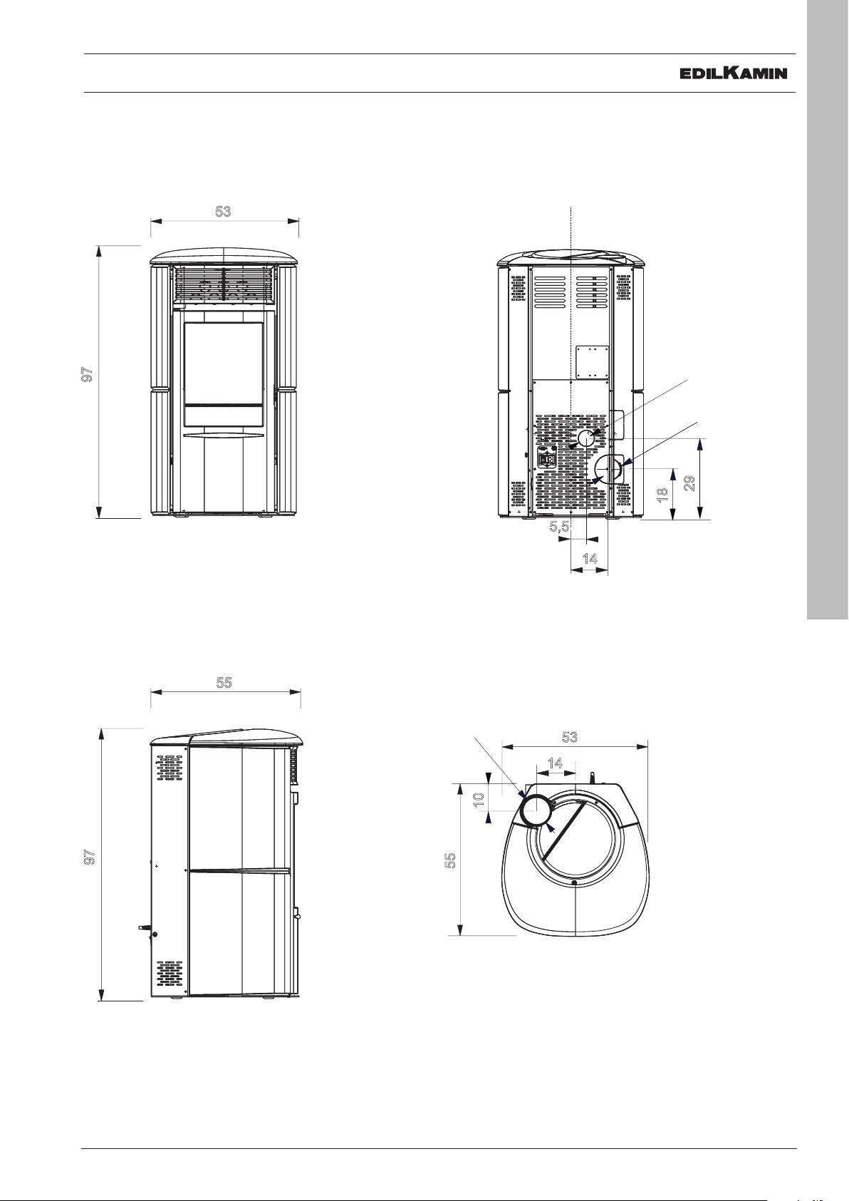
DIMENSIONS (cm)
Ø 4 cm aria
combustione
14
18
Ø 8 cm
uscita fumi
29
5,5
53
Ø 4 cm aria
combustione
97
14
18
53
55
Ø 8 cm
uscita fumi
29
5,5
14
10
Ø 8 cm
uscita fumi
Ø 4 cm aria
combustione
14
18
Ø 8 cm
uscita fumi
29
5,5
97
53
DIMENSIONS
Combustion air
Ø 4 cm aria
Ø 40 mm
combustione
Smoke outlet
Ø 8 cm
Ø 80 mm
uscita fumi
29
18
97
55
Smoke outlet
Ø 8 cm
Ø 80 mm
uscita fumi
55
10
5,5
14
53
14
ENGLISH
5
USER/INSTALLER
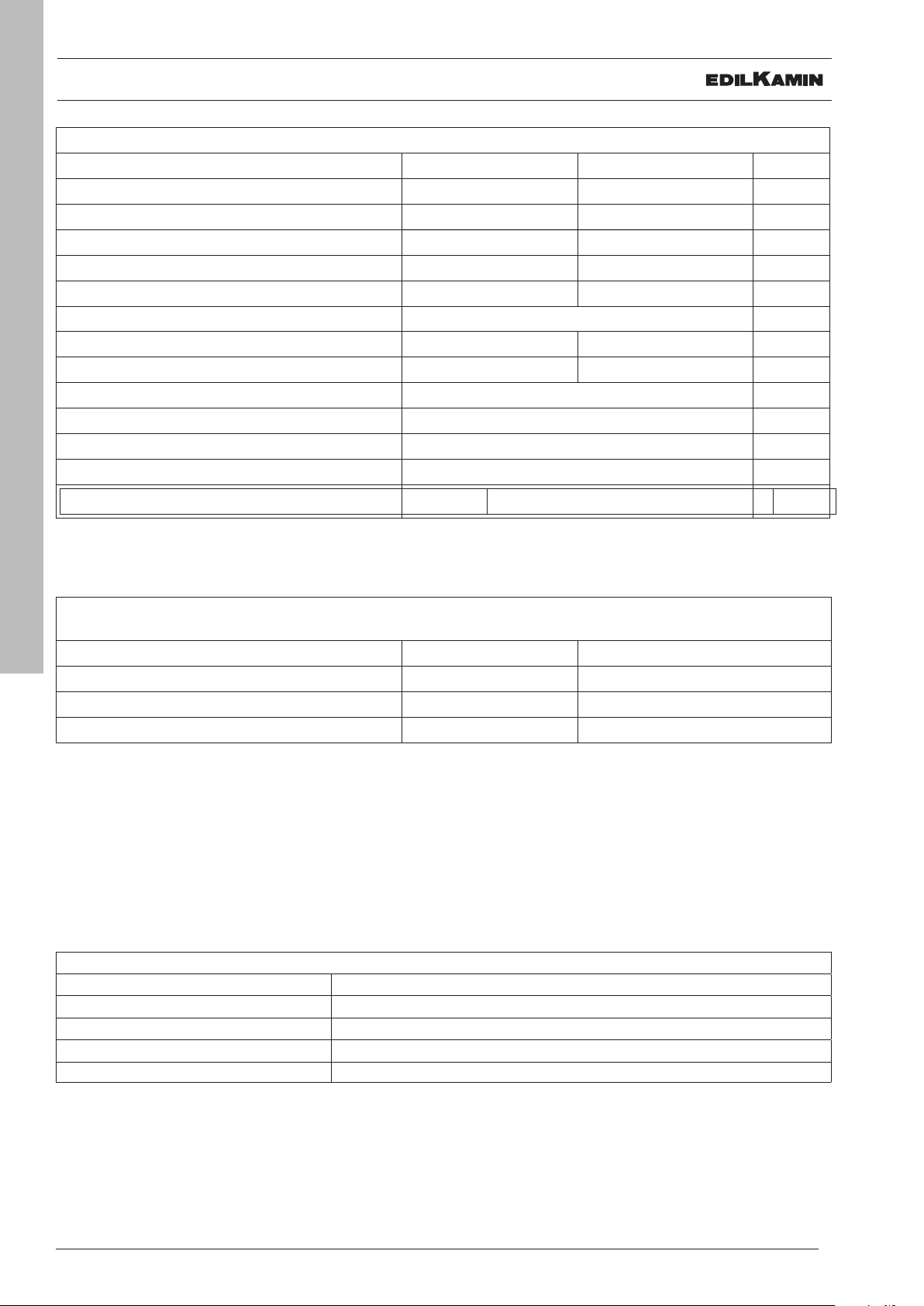
TECHNICAL CHARACTERISTICS
TECHNICAL CHARACTERISTICS per EN 14785
Nominal power Reduced power
Available power
Efficiency 88,7 89,7 %
CO emissions at 13% O
Fumes temperature 130 93 °C
Fuel consumption 1,9 0,6 kg/h
Tank capacity 15 kg
Draw 11,2 8,9 Pa
Autonomy 8 25 hours
Heatable volume * 215 m
Fumes outlet diameter (male) 80 mm
Air intake diameter (male) 40 mm
Weight including packaging (steel/glas/stone) 147/160/177 kg
UE 2015-1186 (A++/G) A+
2
8,2 2,5 kW
0,004 0,018 %
3
TECHNICAL DATA FOR RATING THE FLUE
which must in any case satisfy the requirements of this sheet and the installation instructions for the product
ENGLISH
Fumes temperature at outlet 156 °C
6
Nominal power
Minimum draw 0,01 Pa
Fumes flow rate 9,4 g/s
* The heatable volume is calculated for a house insulated pursuant to Italian Law 10/91 and subsequent amendments,
and a heating demand of 33 Kcal/m³ hour, pellet 4,8 kW/kg
ELECTRICAL SPECIFICATIONS
Power 230 Vac +/- 10% 50 Hz
Mean absorbed power 132-50 W
Power absorption during ignition 300 W
Remote control frequency (provided) 2,4 GHz
Protection Fuse 4 AT, 250 Vac 5x20
The above data are illustrative and are drawn from the certification by a notified body.
EDILKAMIN s.p.a. reserves the right to modify the product without notification in the interests of improvement.
USER/INSTALLER
UNPACKING
PREPARATION AND UNPACKING
The packaging materials are neither toxic nor noxious
and do not require special disposal.
The end user is responsible for storing, disposing of
and recycling them in a regulatory fashion.
Always move the stove vertically with
suitable equipment and in compliance with
safety regulations.
Do not turn the package over, and handle
all parts requiring installation with care.
PACKAGING
ARIS UP CERAMIC-
The delivery consists of the following packages:
• one containing the stove's frame
• one containing the claddings (see details in the
assembly chapter)
• the multiple smoke outlet Kit
ARIS UP STEEL
The delivery consists of the following packages:
• one containing the stove's frame and the steel
sides (already fitted)
• one, on top of the stove package, containing the
ceramic cladding (see details in the assembly
chapter)
• the multiple smoke outlet Kit
ARIS UP STONE
The package contains:
• a package with the cladding (already fitted);
• the multiple smoke outlet Kit
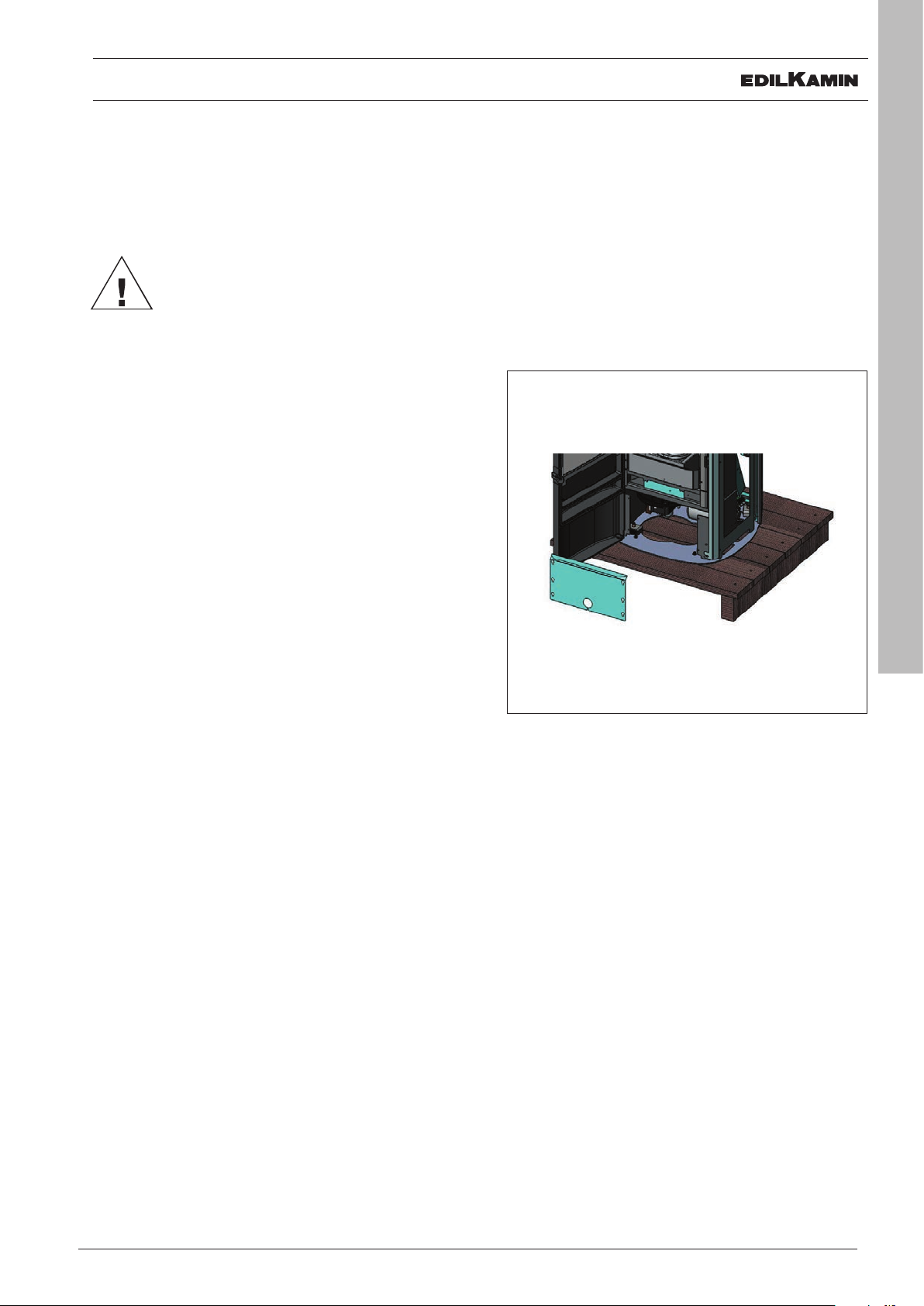
TO REMOVE THE STOVE FROM THE PALLET
• Open the combustion chamber door using the
removable handle
• loosen the 4 screws to remove the galvanised
front panel
• remove the 2 screws fixed to the pallet
• refit the galvanised panel and tighten the 4 fixing
screws.
ENGLISH
7
The package with the stove contains:
• remote control,
• warranty certificate,
• glove,
• this manual,
• power cable,
• protective lever (removable handle) for the
combustion chamber door
INSTALLER
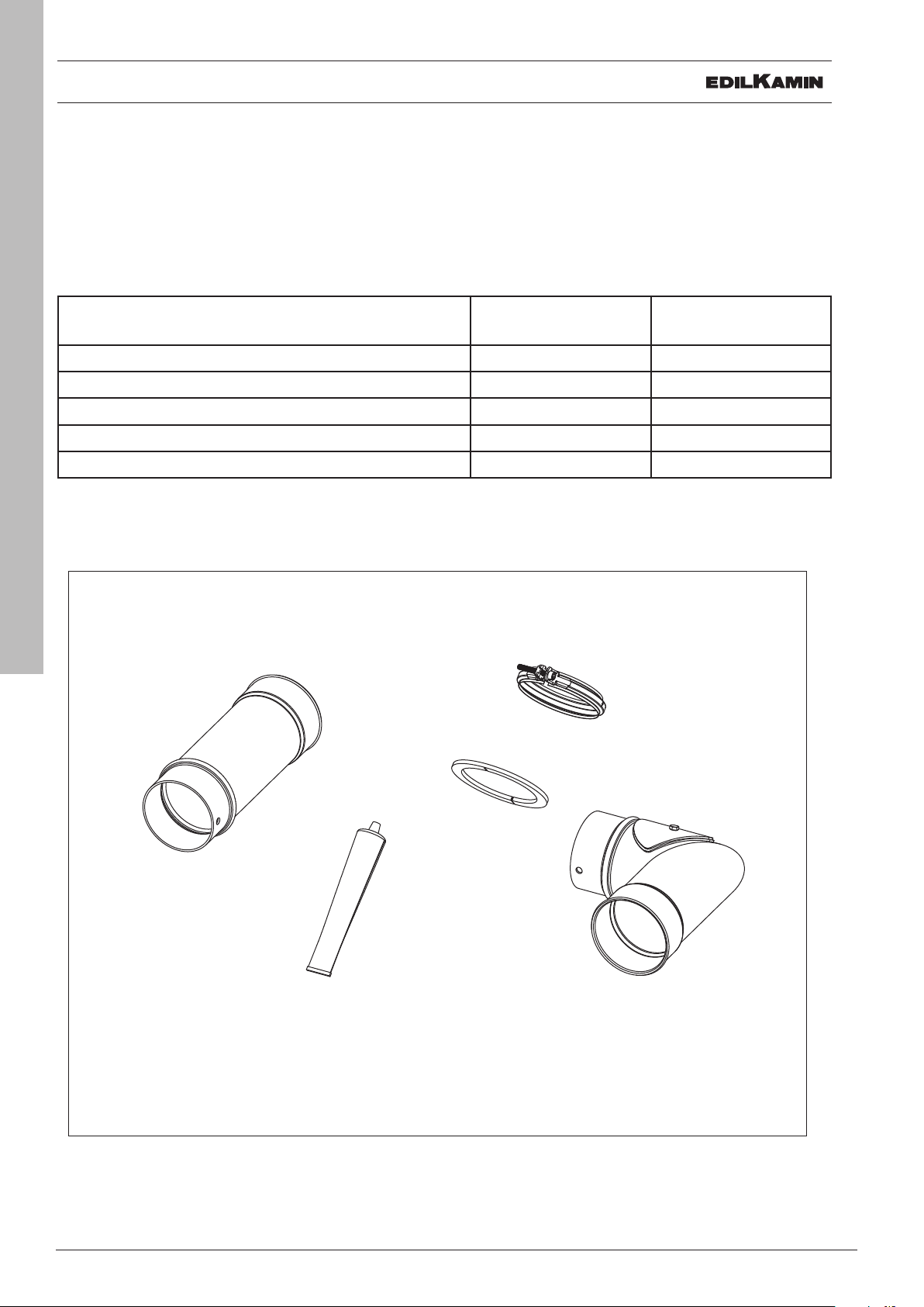
ORIENTATION OF THE SMOKE OUTLET
SMOKE OUTLET
The stove can have its smoke outlet pipe connected to the top or the rear.
To use the rear smoke outlet, proceed as follows. Only perform work with the electrical power
disconnected
Use the smoke outlet Kit provided for the connection, as shown below
Description Reference in
Quantity
gure
Joint clamp F
Elbow-union - Pipe Ø 8 cm with inspection door L 1
Silicone tube S 1
Fume pipe section Ø 8 cm H 1
Rosette flange U 1
ENGLISH
8
H
F
S
INSTALLER
U
L
G
I
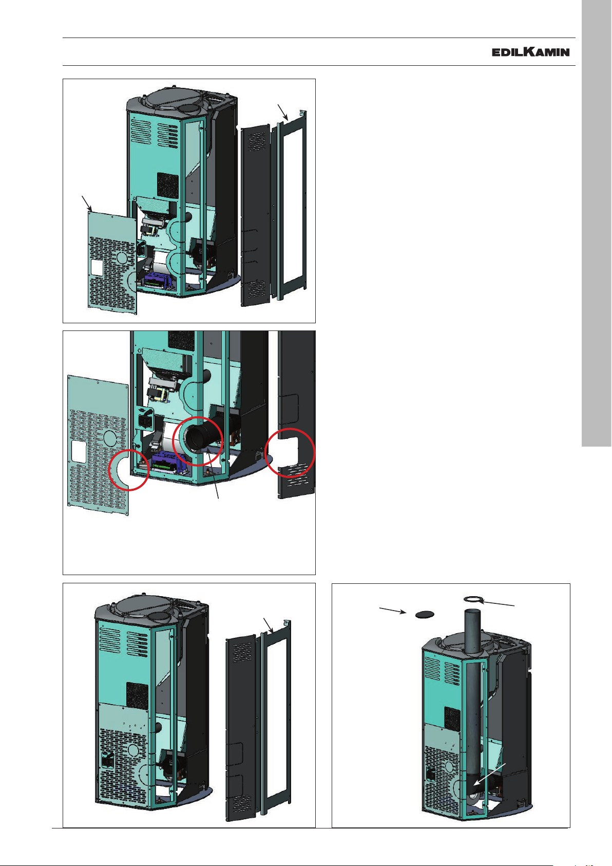
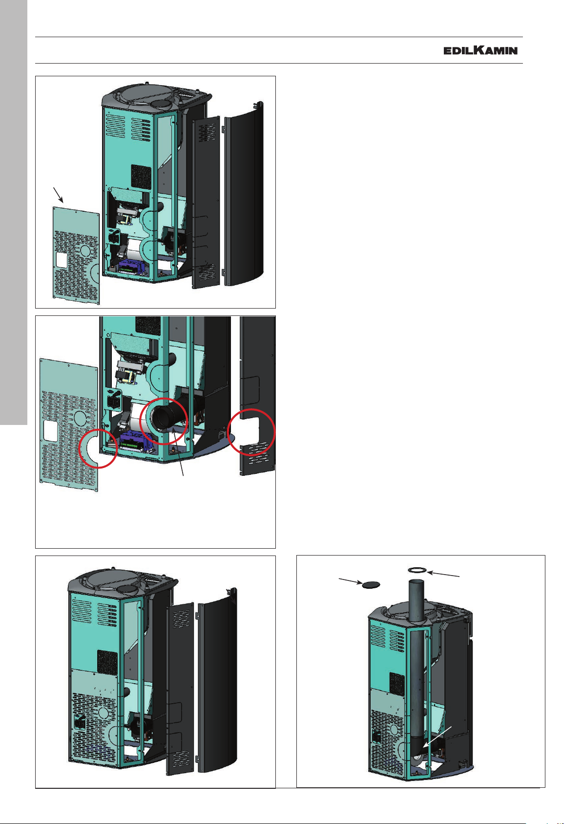
FUME DISCHARGE
ARIS UP CERAMIC
B
The CERAMIC version of ARIS is configured for connecting the fume discharge pipe to the rear and to
the top.
WHATEVER SOLUTION IS USED TO CON-
NECT THE FUME OUTLET TO THE FLUE,
IT IS NECESSARY TO REMOVE THE LEFT-
A
A
HAND REAR METAL SIDE (A) AND THE
LEFT-HAND METAL FRAME (B).
NB: add silicone (provided) between the fume volute
inlet and the elbow union provided (for fume discharge from top), or to the pipe section provided (for
fume discharge from rear).
FUME DISCHARGE FROM REAR
Remove the lower rear panel (G).
Remove the pre-cut section* from the previously
removed lower rear panel (G) and from the left-hand
rear metal side (A).
Remove the pre-cut section (I ) from the stove structure.
Connect the flue section (H, provided) onto the fume
volute inlet using the clamp provided.
G
*
*
H
*
B
FUME DISCHARGE FROM TOP
Mount the elbow union with clamp (L) provided onto
the fume volute inlet.
Remove the cover on top (Q - Fig. 15).
Connect the fume discharge pipe (not provided) to
the aforementioned elbow union .
Insert the rose (U ) provided.
AFTER CONNECTING THE FUME DIS-
CHARGE PIPE TO THE FLUE, RE-ATTACH
THE LEFT-HAND REAR METAL SIDE (A)
AND THE LEFT-HAND METAL FRAME (B).
Q
U
ENGLISH
9
A
L
INSTALLER
ENGLISH
10
G
G
I
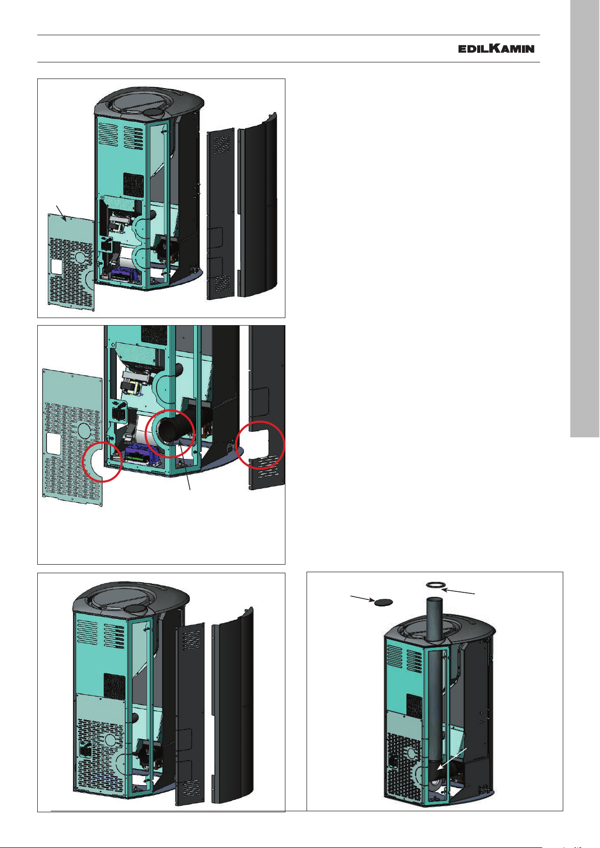
FUME DISCHARGE
ARIS UP STEEL
The STEEL version of ARIS is configured for connecting the
fume discharge pipe to the rear and to the top.
WHATEVER SOLUTION IS USED TO CONNECT
B
A
THE FUME OUTLET TO THE FLUE, IT IS NECESSARY TO REMOVE THE LEFT-HAND REAR MET-
AL SIDE (A - Fig. 16-18) AND THE LEFT-HAND
METAL SIDE (B ).
NB: add silicone (provided) between the fume volute inlet
and the elbow union provided (for fume discharge from
top), or to the pipe section provided (for fume discharge
from rear).
FUME DISCHARGE FROM REAR
Remove the lower rear portion (G).
Remove the pre-cut section * from the previously removed lower rear portion (G) and from the left-hand rear
metal side (A).
Remove the pre-cut section (I ) from the stove structure.
Connect the flue section (H, provided) onto the fume volute
inlet using the clamp provided.
A
FUME DISCHARGE FROM TOP
Mount the elbow union suing the clamp (L) provided onto
the fume volute inlet.
Remove the cover on top (Q).
Connect the fume discharge pipe (not provided) to the
aforementioned elbow union .
Insert the rose (U) provided.
*
*
H
A
B
*
AFTER CONNECTING THE FUME DISCHARGE
PIPE TO THE FLUE, RE-ATTACH THE LEFT-
HAND REAR METAL SIDE (A) AND THE LEFT-
HAND METAL SIDE (B).
Q
U
L
INSTALLER
G
G
I
FUME DISCHARGE
ARIS UP STONE
The POTSTONE version of ARIS is configured for connecting the fume discharge pipe to the rear and to the top.
WHATEVER SOLUTION IS USED TO CONNECT
THE FUME OUTLET TO THE FLUE, IT IS NECESSARY TO REMOVE THE LEFT-HAND REAR MET-
B
A
AL SIDE (A - Fig. 20-22) AND THE LEFT-HAND
METAL FRAME INCLUDING THE POTSTONE
LINING (B).
NB: add silicone (provided) between the fume volute inlet
and the elbow union provided (for fume discharge from
top), or to the pipe section provided (for fume discharge
from rear).
FUME DISCHARGE FROM REAR
Remove the lower rear portion (G).
Remove the pre-cut section * from the previously removed lower rear portion (G) and from the left-hand rear
metal side (A).
Remove the pre-cut section (I ) from the stove structure.
Connect the flue section (H , provided) onto the fume volute inlet using the clamp provided.
A
FUME DISCHARGE FROM TOP
Mount the elbow union using the clamp (L) provided onto
the fume volute inlet.
Remove the cover on top (Q ).
Connect the fume discharge pipe (not provided) to the
aforementioned elbow union .
Insert the rose (U) provided.
ENGLISH
11
*
*
H
A
*
B
AFTER CONNECTING THE FUME DISCHARGE
PIPE TO THE FLUE, RE-ATTACH THE LEFT-
HAND REAR METAL SIDE (A) AND THE LEFTHAND METAL FRAME INCLUDING THE POT-
STONE LINING (B).
Q
U
L
INSTALLER
 Loading...