

PELLET STOVE
ARIS UP2
EN Installation, use and maintenance page 2

CONTENTS
Introduction and readers of this manual 3
Safety information 4
Dimensions 5
Technical data 6
Unpacking 7
Smoke discharge direction 8
Covering Ceramic 12
Covering Steel 14
Installation 15
Instructions for use 19
Maintenance 28
Troubleshooting 31
The original language of this edition is Italian
ENGLISH
2
The undersigned company, EDILKAMIN S.p.A., with
registered office in Via Vincenzo Monti 47 - 20123 Milan
(Italy) - Italian Tax ID VAT NO. 00192220192
Hereby declares, under its sole responsibility, that:
The pellet stoves mentioned below comply with EU
Regulation 305/2011 and the harmonised EU standard
EN 14785:2006
PELLET STOVES, bearing the
EDILKAMIN brand, called
ARIS UP2
SERIAL NO.: Rating plate reference
ARIS UP2 : Performance declaration: (DoP - EK no. 171)
Moreover, the company hereby declares that:
the ARIS UP2 wood pellet stoves satisfy the requirements of
the following European directives:
2014/35/EC - Low Voltage Directive
2014/30/EC - Electromagnetic Compatibility Directive
USER/INSTALLER
Dear Sir/Madam
We thank you for and congratulate you on choosing our
product. Before using it, we would ask you to read this
manual carefully, so that you can make the most of all its
functions in total safety.
This manual is an integral part of the product. We ask you
to keep it for the entire lifetime of the product. If you lose it,
you can request a copy from your dealer or download it from
www.edilkamin.com.
Readers of the manual
This manual is addressed to:
• those who use the product at home (“USER”);
• the technician who will install the product (“INSTALLER”)
The target person of each page is indicated in a band at the
bottom of the page (USER or INSTALLER).
General information
After unpacking the product, check the condition and
completeness of the contents.
In the event of error, immediately contact the retailer where
the purchase was made, providing him with a copy of the
warranty booklet and sales receipt.
The appliance must be installed and operated in compliance
with local and national law and European regulations. For the
installation, and for anything not specifically indicated in the
manual, observe local regulations.
The diagrams provided in this manual are for illustration
purposes only: they do not always strictly refer to your
specific model, and are not binding in any way.
Product identication and warranty.
The product is uniquely identified by a number, the
“counterfoil”, which is indicated on the warranty certificate.
Please keep:
• the warranty certificate accompanying the product
• the purchase receipt given to you by the retailer
• the declaration of conformity given to you by the installer.
The warranty conditions are given in the warranty certificate
accompanying the product.
First ignition is required, in Italy, by an authorised
technician in accordance with UNI 10683, and is
recommended in all countries to ensure best results from
the product.
This consists of:
• checking the installation documents (declaration of
conformity) and the quality of the installation itself
• calibrating the product to suit its actual application
• providing explanations to the end user and issuing
the complementary documentation (first ignition -
commissioning certificate)
Having the appliance commissioned properly ensures that it
will operate to best effect and in complete safety.
First ignition is required for activation of the Edilkamin
manufacturer warranty. The warranty is only valid in the
country where the product was bought.
If the appliance is not commissioned by an authorised
technician, Edilkamin will not provide warranty service. See
the warranty booklet for details. The above terms do not
affect the dealer’s legal responsibility for the legal warranty.
ENGLISH
3
MEANING OF SYMBOLS
In some parts of the manual the following symbols are
used:
PLEASE NOTE:
carefully read and understand the
message in question, since failure to
follow the instructions in it could cause
serious damage to the product and put
the safety of those using it at risk.
INFORMATION:
failure to comply with these requirements
will compromise product use.
OPERATING SEQUENCE:
follow the instructions for the operations
described.
The warranty, however, covers only demonstrable
manufacturing defects and not, for instance, problems
resulting from improper installation or calibration.
USER/INSTALLER

SAFETY INFORMATION
• The product is not designed for use by people,
including children, with limited physical, sensory
and mental abilities.
• The appliance is not designed for cooking
purposes.
• The appliance is designed to burn UNI EN ISO
17225-2 category A1 wood pellets, in the amounts
and manner described in this manual.
• The appliance is designed for indoor use and in
areas with normal humidity conditions.
• Keep the product in a dry place out of the weather.
• For the legal and company warranties, refer to the
warranty certificate inside the product: specifically,
neither Edilkamin nor the retailer are liable for
damage resulting from incorrect installation or
maintenance.
Safety risks may be caused by:
• Installation in non-suitable settings, in particular
those that are subject to fire risks. DO NOT
INSTALL THE PRODUCT IN AREAS SUBJECT TO
THE RISK OF FIRE.
• Contact with fire and hot parts (e.g. glass panel
and pipes). DO NOT TOUCH HOT PARTS and,
when the stove is switched off and still hot, always
ENGLISH
4
wear the glove supplied.
• Contact with live electrical equipment (internal).
DO NOT ACCESS THE INTERNAL ELECTRICAL
EQUIPMENT WHILE THE APPLIANCE IS
POWERED ON. Electrocution hazard.
• Use of improper ignition aids (e.g. alcohol). DO
NOT IGNITE OR BOOST THE FLAME WITH FLUID
SPRAYS OR A FLAME TORCH. Serious risk of
burns, damage and injury.
• Use of fuel other than wood pellets. DO NOT BURN
WASTE MATTER, PLASTIC OR MATERIALS OTHER
THAN WOOD PELLETS IN THE COMBUSTION
CHAMBER. The product may become soiled, the
flue may catch fire, and environmental damage
may ensue.
• Cleaning the combustion chamber when hot. DO
NOT CLEAN WITH A VACUUM CLEANER WHEN
HOT. You could damage the vacuum-cleaner and
risk the emission of smoke in the room.
• Cleaning the smoke duct with cleaning products.
DO NOT CLEAN THE PRODUCT WITH
FLAMMABLE PRODUCTS. Risk of fire or blowback.
• Cleaning the glass pane while hot or with unsuitable
cleaning products. DO NOT CLEAN HOT GLASS
WITH WATER. ONLY USE RECOMMENDED
GLASS CLEANING PRODUCTS. Risk of cracking
and permanent, irreparable damage to the glass.
• The storage of flammable materials at a distance
which is less than the safe distances listed in
this manual. DO NOT PLACE LAUNDRY ON
THE APPLIANCE. DO NOT PLACE DRYING
RACKS WITHIN THE SAFETY CLEARANCE. Keep
flammable fluids away from the appliance. Fire
hazard.
• Blocking the aeration vents and air intakes in the
room. DO NOT BLOCK THE AERATION VENTS
OR FLUE. Risk of smoke returning into the room
with consequent damage and injury.
• Use of the product as a support or ladder. DO
NOT CLIMB ONTO THE PRODUCT OR USE IT AS
A SUPPORT. Risk of damage and injury.
• Use of the stove with the combustion chamber
open. DO NOT USE THE PRODUCT WITH ITS
DOOR OPEN.
• Incandescent material may come out from the
open door. DO NOT throw incandescent material
outside the appliance. Fire hazard.
• Use of water in case of fire. CALL THE
AUTHORITIES if a fire breaks out.
• If you have doubts, please do not take any action,
but contact the retailer or the installer.
For reasons of safety, read the user instructions
included in this manual.
USER/INSTALLER
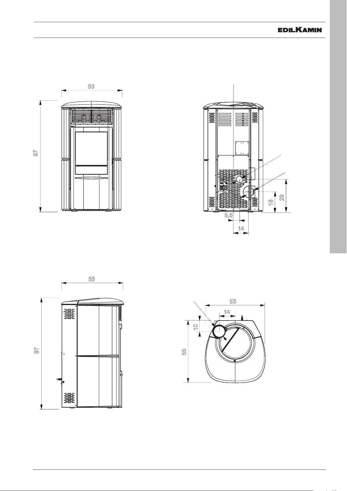
DIMENSIONS (cm)
Ø 4 cm aria
combustione
14
18
Ø 8 cm
uscita fumi
29
5,5
53
Ø 4 cm aria
combustione
97
14
18
53
55
Ø 8 cm
uscita fumi
29
5,5
14
10
Ø 8 cm
uscita fumi
Ø 4 cm aria
combustione
14
18
Ø 8 cm
uscita fumi
29
5,5
97
53
DIMENSIONS
Combustion air
Ø 4 cm aria
Ø 40 mm
combustione
Smoke outlet
Ø 8 cm
Ø 80 mm
uscita fumi
29
18
97
55
Smoke outlet
Ø 8 cm
Ø 80 mm
uscita fumi
55
10
5,5
14
53
14
ENGLISH
5
USER/INSTALLER
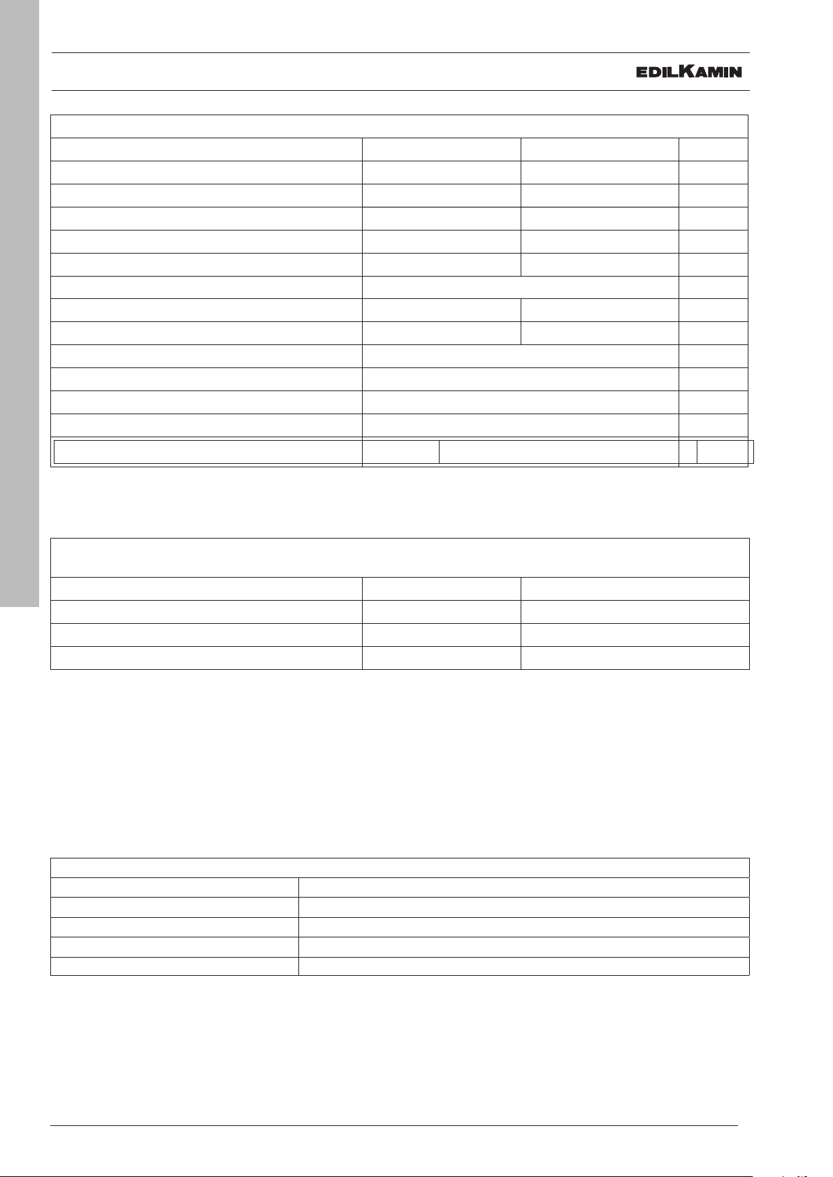
TECHNICAL CHARACTERISTICS
TECHNICAL CHARACTERISTICS per EN 14785
Nominal power Reduced power
Available power
Efficiency 88,7 89,7 %
CO emissions at 13% O
Fumes temperature 130 93 °C
Fuel consumption 1,9 0,6 kg/h
Tank capacity 15 kg
Draw 11,2 8,9 Pa
Autonomy 8 25 hours
Heatable volume * 215 m
Fumes outlet diameter (male) 80 mm
Air intake diameter (male) 40 mm
Weight including packaging (steel/glas/stone) 147/160/177 kg
UE 2015-1186 (A++/G) A+
2
8,2 2,5 kW
0,004 0,018 %
3
TECHNICAL DATA FOR RATING THE FLUE
which must in any case satisfy the requirements of this sheet and the installation instructions for the product
ENGLISH
Fumes temperature at outlet 156 °C
6
Nominal power
Minimum draw 0,01 Pa
Fumes flow rate 9,4 g/s
* The heatable volume is calculated for a house insulated pursuant to Italian Law 10/91 and subsequent amendments,
and a heating demand of 33 Kcal/m³ hour, pellet 4,8 kW/kg
ELECTRICAL SPECIFICATIONS
Power 230 Vac +/- 10% 50 Hz
Mean absorbed power 132-50 W
Power absorption during ignition 300 W
Remote control frequency (provided) 2,4 GHz
Protection Fuse 4 AT, 250 Vac 5x20
The above data are illustrative and are drawn from the certification by a notified body.
EDILKAMIN s.p.a. reserves the right to modify the product without notification in the interests of improvement.
USER/INSTALLER
UNPACKING
PREPARATION AND UNPACKING
The packaging materials are neither toxic nor noxious
and do not require special disposal.
The end user is responsible for storing, disposing of
and recycling them in a regulatory fashion.
Always move the stove vertically with
suitable equipment and in compliance with
safety regulations.
Do not turn the package over, and handle
all parts requiring installation with care.
PACKAGING
ARIS UP CERAMIC-
The delivery consists of the following packages:
• one containing the stove's frame
• one containing the claddings (see details in the
assembly chapter)
• the multiple smoke outlet Kit
ARIS UP STEEL
The delivery consists of the following packages:
• one containing the stove's frame and the steel
sides (already fitted)
• one, on top of the stove package, containing the
ceramic cladding (see details in the assembly
chapter)
• the multiple smoke outlet Kit
ARIS UP STONE
The package contains:
• a package with the cladding (already fitted);
• the multiple smoke outlet Kit
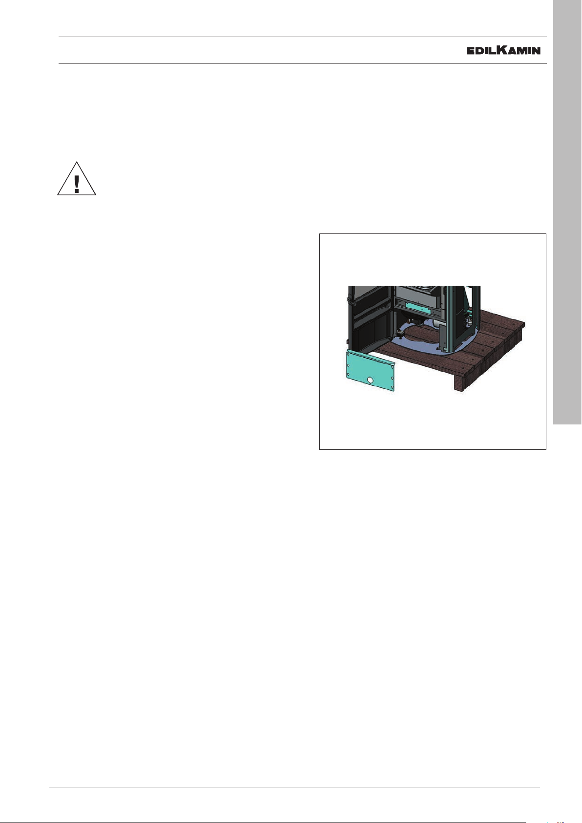
TO REMOVE THE STOVE FROM THE PALLET
• Open the combustion chamber door using the
removable handle
• loosen the 4 screws to remove the galvanised
front panel
• remove the 2 screws fixed to the pallet
• refit the galvanised panel and tighten the 4 fixing
screws.
ENGLISH
7
The package with the stove contains:
• remote control,
• warranty certificate,
• glove,
• this manual,
• power cable,
• protective lever (removable handle) for the
combustion chamber door
INSTALLER
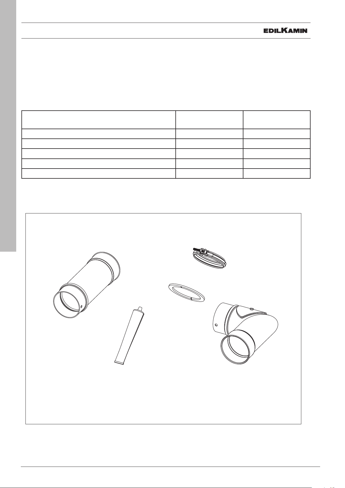
ORIENTATION OF THE SMOKE OUTLET
SMOKE OUTLET
The stove can have its smoke outlet pipe connected to the top or the rear.
To use the rear smoke outlet, proceed as follows. Only perform work with the electrical power
disconnected
Use the smoke outlet Kit provided for the connection, as shown below
Description Reference in
Quantity
gure
Joint clamp F
Elbow-union - Pipe Ø 8 cm with inspection door L 1
Silicone tube S 1
Fume pipe section Ø 8 cm H 1
Rosette flange U 1
ENGLISH
8
H
F
S
INSTALLER
U
L
G
I
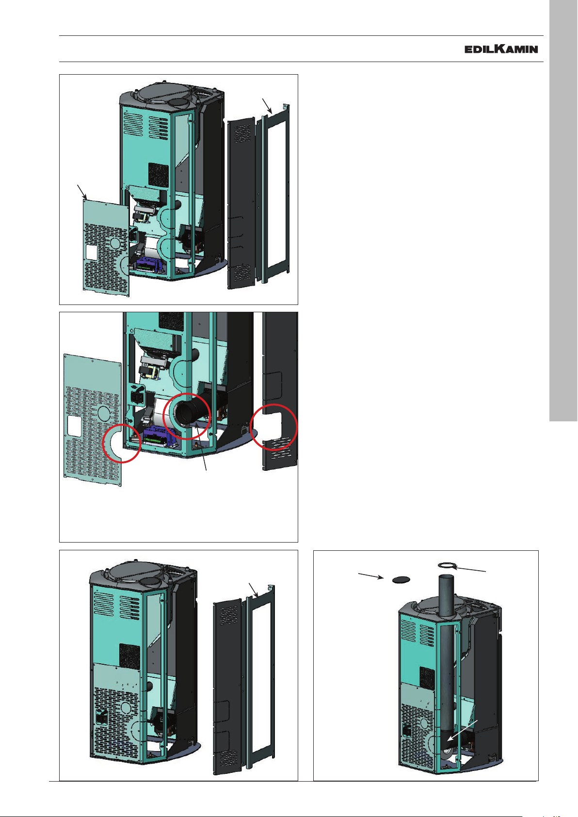
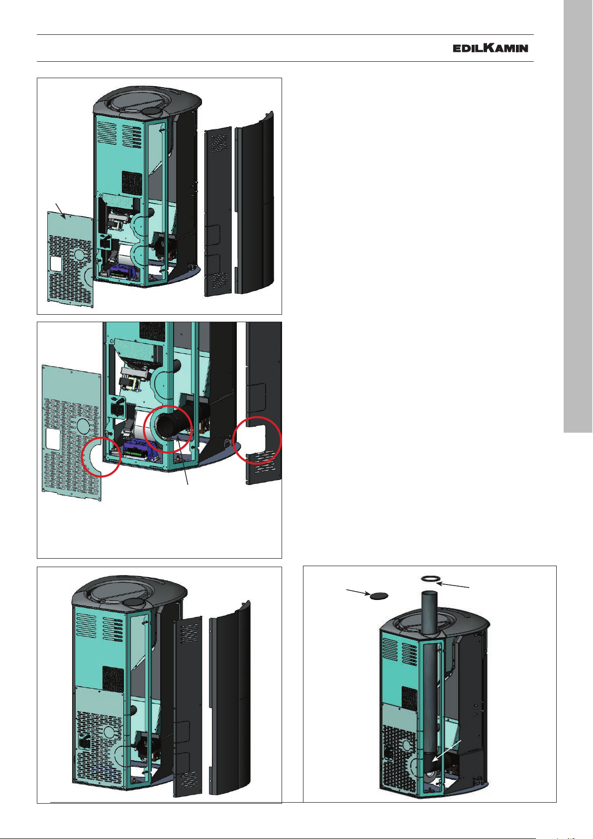
FUME DISCHARGE
ARIS UP CERAMIC
B
The CERAMIC version of ARIS is configured for connecting the fume discharge pipe to the rear and to
the top.
WHATEVER SOLUTION IS USED TO CON-
NECT THE FUME OUTLET TO THE FLUE,
IT IS NECESSARY TO REMOVE THE LEFT-
A
A
HAND REAR METAL SIDE (A) AND THE
LEFT-HAND METAL FRAME (B).
NB: add silicone (provided) between the fume volute
inlet and the elbow union provided (for fume discharge from top), or to the pipe section provided (for
fume discharge from rear).
FUME DISCHARGE FROM REAR
Remove the lower rear panel (G).
Remove the pre-cut section* from the previously
removed lower rear panel (G) and from the left-hand
rear metal side (A).
Remove the pre-cut section (I ) from the stove structure.
Connect the flue section (H, provided) onto the fume
volute inlet using the clamp provided.
G
*
*
H
*
B
FUME DISCHARGE FROM TOP
Mount the elbow union with clamp (L) provided onto
the fume volute inlet.
Remove the cover on top (Q - Fig. 15).
Connect the fume discharge pipe (not provided) to
the aforementioned elbow union .
Insert the rose (U ) provided.
AFTER CONNECTING THE FUME DIS-
CHARGE PIPE TO THE FLUE, RE-ATTACH
THE LEFT-HAND REAR METAL SIDE (A)
AND THE LEFT-HAND METAL FRAME (B).
Q
U
ENGLISH
9
A
L
INSTALLER
ENGLISH
10
G
G
I
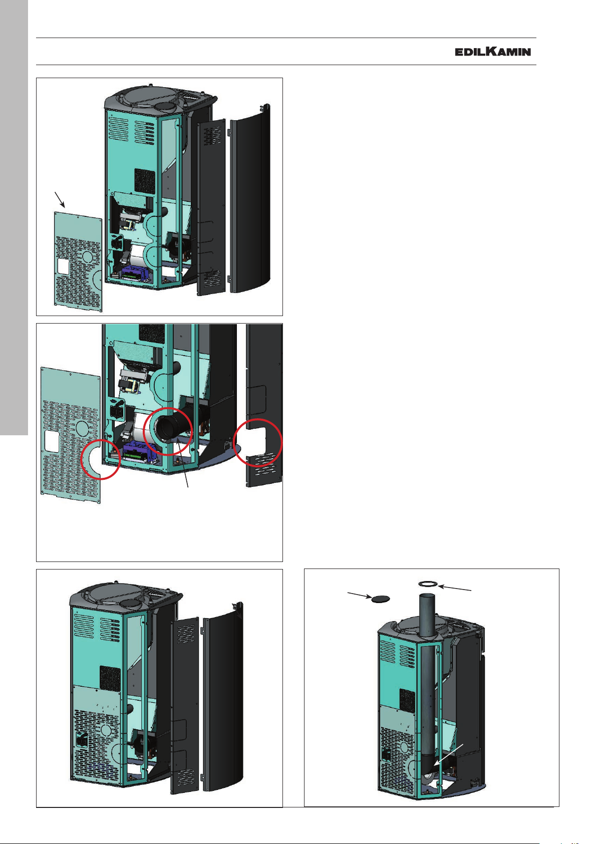
FUME DISCHARGE
ARIS UP STEEL
The STEEL version of ARIS is configured for connecting the
fume discharge pipe to the rear and to the top.
WHATEVER SOLUTION IS USED TO CONNECT
B
A
THE FUME OUTLET TO THE FLUE, IT IS NECESSARY TO REMOVE THE LEFT-HAND REAR MET-
AL SIDE (A - Fig. 16-18) AND THE LEFT-HAND
METAL SIDE (B ).
NB: add silicone (provided) between the fume volute inlet
and the elbow union provided (for fume discharge from
top), or to the pipe section provided (for fume discharge
from rear).
FUME DISCHARGE FROM REAR
Remove the lower rear portion (G).
Remove the pre-cut section * from the previously removed lower rear portion (G) and from the left-hand rear
metal side (A).
Remove the pre-cut section (I ) from the stove structure.
Connect the flue section (H, provided) onto the fume volute
inlet using the clamp provided.
A
FUME DISCHARGE FROM TOP
Mount the elbow union suing the clamp (L) provided onto
the fume volute inlet.
Remove the cover on top (Q).
Connect the fume discharge pipe (not provided) to the
aforementioned elbow union .
Insert the rose (U) provided.
*
*
H
A
B
*
AFTER CONNECTING THE FUME DISCHARGE
PIPE TO THE FLUE, RE-ATTACH THE LEFT-
HAND REAR METAL SIDE (A) AND THE LEFT-
HAND METAL SIDE (B).
Q
U
L
INSTALLER
G
G
I
FUME DISCHARGE
ARIS UP STONE
The POTSTONE version of ARIS is configured for connecting the fume discharge pipe to the rear and to the top.
WHATEVER SOLUTION IS USED TO CONNECT
THE FUME OUTLET TO THE FLUE, IT IS NECESSARY TO REMOVE THE LEFT-HAND REAR MET-
B
A
AL SIDE (A - Fig. 20-22) AND THE LEFT-HAND
METAL FRAME INCLUDING THE POTSTONE
LINING (B).
NB: add silicone (provided) between the fume volute inlet
and the elbow union provided (for fume discharge from
top), or to the pipe section provided (for fume discharge
from rear).
FUME DISCHARGE FROM REAR
Remove the lower rear portion (G).
Remove the pre-cut section * from the previously removed lower rear portion (G) and from the left-hand rear
metal side (A).
Remove the pre-cut section (I ) from the stove structure.
Connect the flue section (H , provided) onto the fume volute inlet using the clamp provided.
A
FUME DISCHARGE FROM TOP
Mount the elbow union using the clamp (L) provided onto
the fume volute inlet.
Remove the cover on top (Q ).
Connect the fume discharge pipe (not provided) to the
aforementioned elbow union .
Insert the rose (U) provided.
ENGLISH
11
*
*
H
A
*
B
AFTER CONNECTING THE FUME DISCHARGE
PIPE TO THE FLUE, RE-ATTACH THE LEFT-
HAND REAR METAL SIDE (A) AND THE LEFTHAND METAL FRAME INCLUDING THE POT-
STONE LINING (B).
Q
U
L
INSTALLER

COVERING CERAMIC
fig. 1
fig. 2
ENGLISH
12
C
C
B
A
B
A
A
1) VERSION WITH CERAMIC SIDES AND
TOP
Fig. 1
The stove is delivered (Fig. 1) with the following external
components already installed:
• metal rear sides (A)
• metal frames for fixing the ceramic side elements (B)
• cast iron upper grille (C)
The pieces indicated below are packaged separately.
• 4 ceramic side elements (D - Fig. 3)
• 1 upper horizontal ceramic element (E - Fig. 7)
• 1 ceramic top (F - fig. 9)
• 16 milled pins M4
• 16 washers M5
• 4 rubber pads (M)
• 4 brass washers
• 2 screws T.E. M6x10
To t proceed as follows:
Fig. 2
Remove the two metal rear sides (A) screwed onto the
structure.
Remove the metal frames (B) by loosening the screws.
Remove the cast iron upper grille (C) screwed onto the
structure.
fig. 3
D
D
B
Fig. 3
Attach the vertical ceramic elements (D) to the metal
frames (B) by inserting the M4 knurled bolts with washers
provided through the relevant slots.
B
INSTALLER

COVERING CERAMIC
fig. 4
fig. 5
REAR VIEW
C
C+E
E
B+D
Fig. 4
Fix the upper horizontal ceramic element (E) to the upper
cast iron grid (C) with the two supplied screws M6x10
Fig. 5
Mount the vertical ceramic elements (D) onto the structure
together with the metal frame brackets (B) previously detached from the stove.
A
Mount the upper horizontal ceramic element (F) onto the
structure together with the upper cast iron grille (C) previously detached from the stove.
ENGLISH
fig. 6
M
B+D
F
Lastly, re-mount the two rear metal sides (A) previously
detached from the stove.
Fig. 6
Apply the rubber (M) and the brass washers on the corresponding seats of the cast iron top, then place the ceramic
top.
13
INSTALLER

COVERING STEEL
fig. 7
fig. 8
C
C
A
2) VERSION WITH STEEL SIDES AND
PROFILES AND CERAMIC TOP
Fig. 7
The stove is delivered with metal sides (A) and upper cast
iron grille (C) already mounted.
The parts indicated below are instead packed separately.
• 1 upper horizontal ceramic element (E)
• 1 ceramic top (F)
• 2 milled pins M4
• 2 washers
• 4 rubber pads (M)
• 4 brass washers
• 2 screws T.E. M6x10
To t proceed as follows:
Fig. 8
Remove the cast iron upper grille (C) screwed onto the
structure.
ENGLISH
14
fig. 9
Fig. 9
Fix the upper horizontal ceramic element (E) to the upper
cast iron grid (C) with the two supplied screws M6x10
Fig. 10
Mount the upper horizontal ceramic element (F) back onto
the structure together with the upper cast iron grille (C)
previously detached from the stove.
Apply the rubber (M) and the brass washers on the corresponding seats of the cast iron top, then place the ceramic
top.
fig. 10
REAR VIEW
F
M
C
C+E
E
INSTALLER

INSTALLATION
REMARKS ON INSTALLATION
Note that:
• installation must be carried out by authorised
technical personnel;
• The appliance must be installed and operated
in compliance with local and national law and
European regulations. The applicable Italian
regulation is UNI 10683;
• If installed in a condominium, the appliance must
be approved by the administrator.
We give some general instructions below, however
these do not obviate the need to comply with local
regulations and do not affect the installer’s liability for
the installation.
Checking the suitability of the installation
space
• The room must have a volume of at least 20 m3.
• The floor must be able to bear the weight of the
product and its accessories.
• Level the appliance.
• The appliance may not be installed in a bedroom,
bathroom or in the same room as other equipment
which draws air for combustion from the room
itself, or in any area with an explosive atmosphere.
Any extraction fans operating in the same room or
area as the product, may affect its draw.
• In Italy, check the compatibility pursuant to UNI
10683 and UNI 7129 in the presence of gas fired
products.
Protection from heat and safety clearances
The surfaces of the building adjacent to the product
must be protected against overheating.
The insulation to be used will depend on the type of
surface in question.
The appliance must be installed in accordance with
the following safety instructions:
- minimum clearance at the sides and rear of 20 cm
from flammable materials.
- no flammable materials may be kept closer to the
front of the appliance than 80 cm.
If connected to a wooden or otherwise flammable wall,
the flue must be insulated appropriately.
If installed on a flammable or combustible floor, or one
incapable of bearing its load, use steel or glass plates
under the stove to distribute the load.
Contact the retailer for such optional equipment
Positioning the product
The product is designed to operate in all climatic
conditions. In special circumstances, such as strong
wind, its safety equipment may switch the appliance
off.
Contact the authorised Edilkamin Technical Assistance
Centre.
ENGLISH
15
INSTALLER

INSTALLATION
FLUE SYSTEM
(Smoke duct, ue and chimney pot)
This chapter has been drawn up pursuant to European
regulations EN 13384, EN 1443, EN 1856 and EN
1457. The installer must observe both these and any
other local regulations. This manual does not in any
way substitute such regulations.
The product must be connected to a flue system which
ensures that the smoke produced by combustion are
discharged in complete safety.
Before positioning the appliance, the installer must
check that the flue is suitable.
SMOKE DUCT, FLUE
The smoke duct (which connects the combustion
chamber’s smoke outlet with the flue) and the flue itself
must, among other regulatory requirements:
• receive the smoke from a single product (the
outlets of multiple appliances cannot be conveyed
into a single flue)
• be routed vertically for the most part
• have no downwards sloping sections
• preferably have a circular internal cross section, or
ENGLISH
16
with a ratio of the sides of less than 1.5
• terminate at roof level with a proper chimney pot:
the flue may not discharge directly on the wall
or into an enclosed space, even if the space in
question is open to the sky
• be made of material rated in fire reaction class
A1 as per UNI EN 13501 or analogous national
regulations
• be certified, with a chimney plate if metal
• be of uniform cross section or vary in cross section
only immediately after the outlet, not at some mid
point of its length.
THE SMOKE DUCT
Further to the general requirements for the smoke duct
and flue, the smoke duct:
• may not be made of flexible metal material
• must be insulated, if routed through unheated
areas or outdoors
• must not be routed through rooms where the
installation of combustion heat generators is
prohibited, there is risk of fire, or which cannot be
inspected
• must enable the recovery of soot and be open for
inspection
• have at most 3 bends with a maximum angle of
90°
• must have a single horizontal section with a length
of no more than 3 metres, depending on the draw.
Note, in any case, that long sections promote the
accumulation of dirt and are harder to keep clean.
INSTALLER

INSTALLATION
THE FLUE:
Further to the general prescriptions for the smoke duct
and flue, the flue:
• must serve solely to discharge smoke
• must be correctly sized to satisfy the requirements
of smoke discharge (EN 13384-1)
• should preferably be insulated, in steel with a
circular internal section. If rectangular, the corners
must have a radius of not less than 20 mm, with a
ratio of the internal dimensions of <1.5
• must normally be at least 1.5 metres in vertical
length
• must have a constant cross section
• must be waterproof and thermally insulated to
ensure a good draw
• must preferably have a collection chamber for
non-combusted matter and any condensation.
• if pre-existing, must be clean, to prevent fire
hazards
• in general, we recommend fitting a tube inside the
existing masonry chimney if its diameter is greater
than 150 mm.
INTUBATED SYSTEM:
Further to the general prescriptions for the smoke duct
and flue, the intubated system:
• must operate in negative pressure
• must be open to inspection
• must observe local regulations.
THE CHIMNEY POT
• must be windproof
• must have an internal cross section equivalent to
that of the flue and a smoke outlet at least double
that of the interior of the flue
• for dual flues (which should be spaced at least 2 m
apart) the chimney pot receiving the smoke from
the solid fuel appliance or that from the higher
storey, must be at least 50 cm higher than the other
• it must extend beyond the back flow zone (in Italy,
refer to UNI 10683 point 6.5.8.)
• it must allow for maintenance of the chimney
EXTERNAL AIR INTAKE
In general, we suggest two ways to ensure a proper
flow of combustion air.
Indirect air intake
Install an air outlet at floor level with an effective surface area (net of the screen or other protections) of at
least 80 cm2 (10 cm in diameter).
To prevent draughts, we recommend installing the air
intake behind the stove or behind a radiator.
Installing it in front of the appliance will create
unpleasant draughts.
Direct air intake*
Install an air intake with effective area (net of the mesh
or other protective equipment) at least equal to that of
the air intake at the rear of the product.
Connect the air intake to the appliance’s air intake
with a tube (which may also be flexible). Increase the
diameter of the pipe if it is not smooth: assess its load
loss.
We recommend that it does not exceed 3 metres in
length; if it does, increase the diameter. Reduce the
length by 1 m for each elbow.
The air may be drawn from an adjacent room only if:
• the flow is taken from permanent and unobstructed
openings communicating with the outdoors;
• the adjacent room is never in underpressure
relative to the outdoors;
• the adjacent room is not a garage. subject to fire
hazard, a bathroom or bedroom;
• the adjacent room is not a shared room in the
condominium.
In Italy, UNI 10683 provides that ventilation is sufficient
even if a pressure difference between the outdoors
and indoors of no more than 4 PA is guaranteed (UNI
EN 13384-1). The installer who issues the declaration
of conformity is responsible for ensuring these
conditions.
*The direct connection of the air intake does not make
the product airtight. It is therefore necessary to ensure
an air recovery taken in the room by the product (i.e.
for the glass cleaning)
ENGLISH
17
INSTALLER

INSTALLATION
CHECKING THE ELECTRICAL CONNECTIONS
(the power socket must be located in an
easy to access position)
The stove is equipped with an electrical power cord
or connection to a 230V 50 Hz socket, preferably with
electromagnetic switch.
Variations in voltage of more than 10% can compromise
the operation of the stove.
The electrical system must be compliant; check the
operation of the earth in particular.
Edilkamin is not responsible for malfunctions resulting
from an improperly earthed system.
The power line must be of adequate section for the
power of the appliance.
The power cable must not come into contact with the
flue or other hot parts of the stove.
Power up the stove by setting its switch from 0 to 1.
There is one 4 A fuse on the socket with switch located
at the rear of the stove.
ENGLISH
18
power supply
switchfuse housing
INSTALLER

USER INSTRUCTIONS
FIRST IGNITION (COMMISSIONING) PHASES
• Make sure you have read and understood this
manual
• Remove all flammable materials from the appliance
(manuals, labels, etc.). In particular remove any
labels from the glass
• Make sure that the technician performs the first
ignition and the first loading of the pellet tank (see
“pellet loading”)
On first ignition, there may be a slight
smell of paint, which will disappear in a
short time.
FUEL
Use UNI EN ISO 17225-2 category A1 wood pellets
or similar regulatory products with the following
characteristics.
diameter 6 mm
length 3-4 cm
humidity <10 %
LOADING THE PELLETS INTO THE TANK.
To open the tank, lift the lid
When the stove is hot, DO NOT MAKE
CONTACT between the pellet bag and the
top grille.
Use the provided glove when loading the
stove while it is operating and hence hot to
the touch.
Make sure not to touch the smoke
discharge pipe if hot.
*
For reasons of safety and environmental compatibility,
DO NOT burn plastic, painted wood, coal, bark or
other such materials in the stove.
Do not use the stove as an incinerator
Caution
Using fuels other than those specified can
damage the appliance
ENGLISH
19
USER

USER INSTRUCTIONS
OPERATION
Description. The access to and adjustment of these
functions is described below:
Mode
MANUAL • power level
AUTOMATIC • desired room temperature
CRONO • desired room temperature,
* when lowering the ventilation the stove also
automatically modulates its power to maintain
maximum efficiency.
The stove also has the following supplementary
functions.
Function In which mode it
STAND BY automatic crono when the desired
ENGLISH
20
RELAX manual auto-
NIGHT manual auto-
Size settings
• ventilation level
• ventilation level
selected per day of the week
• ventilation level
can be activated
matic crono
matic
What it does
temperature is
reached, the stove
shuts off and turns
on again when the
temperature drops
enables natural convection mode (fan
off), thus reducing
the power
allows you to set the
stove to go out after
a given number of
hours
PHASES
Further to the above operational procedures, the stove
has the following phases
- Ignition (display reads ON ) Flame ignites and
grows stable
This is the result of:
• manual ignition with ignition button
• request from Crono
• power request during stand by
• request from external contact
Ignition has a variable duration, with the aim of reaching
the start temperature
- Switch-off (display reads OFF )
The flame is extinguished and the stove cools down.
This is the result of:
• manual switch-off with switch-off button
• power demand ceases with Stand by function
active
• request from Crono
• request from external contact
Switch-off has a variable duration, with the aim of
reaching the stop temperature
- Shutdown
Switches the stove off in response to an alarm
INTERFACE
The user interface is the remote control but, if this is not
available, you can control the stove with the button
its rear (see figure)
1. WITH THE STOVE OFF
press the button for 2” to turn the stove on.
2. WITH THE STOVE ON
press the button for 2” to turn the stove off.
3. WITH THE STOVE ON IN MANUAL MODE
by pressing one time and immediately releasing the
button, you can increase the operating power.
on
OPTIONAL CONNECTIONS
The technician can supply, on request:
external thermostat, telephone dialler for connection to
the logic board
USER
simplified
on button

USER INSTRUCTIONS
REMOTE CONTROL
Characteristics:
RF transceiver module, frequency 2.4 GHz - Powered
by two AAA 1.5 V batteries rated at least 1200 mAh.
Risk of explosion if the batteries are replaced with
other batteries of an incorrect type.
ON/OFF button
manual on/off button and for switching the remote
control from energy saving mode to active heating
Buttons:
+: increment button (increases the stove’s power,
temperature or fan speed, etc., or scrolls through the
menu)
-: decrement button (decreases the stove’s power,
temperature or fan speed, etc., or scrolls through the
menu)
M: menu key / relax mode key
OK: confirm key, switches to the next setting and
between automatic and manual modes
REMOTE CONTROL POWER SAVING
If the remote control is not used for 20”, the display
turns off to save power. The display turns black without
text. It is an indication referred to the remote control
only, not to the product state.
The display come back on by pressing the ON/OFF
button.
DO NOT PRESS THE ON/OFF BUTTON
REPEATEDLY; in manual mode, this turns
the product on and off.
NOTES
• The remote control does not store the programs,
which are stored on the logic board; there is thus
no need to reprogram it when it is shut off or
replaced by a new one.
• The remote control exchanges information with the
logic board (including room temperature sensing
for automatic mode operation) every 2’ and when
it is activated by pressing the ON/OFF button.
• In normal use, the batteries of the remote control
should last a year. This is an approximate value,
since it depends on the type of batteries and
the intensity of use. Edilkamin and the retailer
will not consider claims for battery life under any
circumstances. If the battery charge is low, a
warning displays at the top left (see paragraph
“troubleshooting”).
THE TRANSMISSION OF THE
SIGNAL FROM THE REMOTE
CONTROL TO THE PRODUCT IS
CONFIRMED BY A BEEP.
IF THE BEEP IS NOT EMITTED,
THE BUTTON WAS NOT PRESSED
FOR LONG ENOUGH.
ENGLISH
21
ON/OFF
button
REMOTE CONTROL POWER
• Open the bottom of the remote
control and insert the 2 batteries in the
indicated orientation.
• Give power to the appliance.
• PRESS THE ON/OFF BUTTON
WHEN YOU HEAR THE BEEP
Otherwise the remote control will
not work.
If this is the first power on and the language has not yet
been set, the language selection screen will display.
Select the language with the +/- keys and confirm
it with OK. You are now asked to confirm or set the
Time and Date. Set the values with the +/- keys and
confirm with OK. The day of the week is calculated
automatically using a perpetual calendar.
USER

USER INSTRUCTIONS
The display reads the POSSIBLE STATES
described below:
- OFF STATE
The product is shutting down or is off in response to
a manual switching off by using the ON/OFF button
of the remote control or due to an external contact
(crono, phone dialler)
The display shows the current time, room temperature
and the status in relation to which the product is OFF.
The product is OFF:
due to manual operation of the user (fig. 1)
due to power failure (fig. 2)
due to shut off by Crono mode (fig. 3)
Fig. 4
If timer programming is active, 3 and 4 are replaced by
the day’s timer programming with the current setpoint
at the centre (figure 5) and the temperature displayed
at the top right.
ENGLISH
22
Fig. 1
From the OFF screen, press the ON/OFF button for 3
seconds to switch to the ON screen.
Pressing the +/- keys has no effect.
Pressing the M key displays the menu.
- ON STATE
The product is ready
The display shows (figure 4)
1. the current time
2. the current room temperature
3. the room temperature setting or manual mode
4. the power level (represented by the flames)
5. the fan level (represented by the filling in of the
blades)
Fig. 2 Fig. 3
Fig. 5
- ALARM STATE
In case of shutdown due to alarm, 4 is replaced by a
message indicating the type of shutdown (figure 6)
H1
Fig. 6
- STAND BY STATE
Situation in which there is no demand for heating.
If the Stand By function is active, the display shows the
same information as in the ON state without flame (on
the top left you will see “STB”).
USER
While in stand-by mode, and ON, the
product turns on only if there is a heat
request

USER INSTRUCTIONS
USER CONTROLS (REMOTE CONTROL)
- ON/OFF
- Switch-on/switch-off
- Manual mode setting
• Power setting
• Fan setting
- Automatic mode setting
• Temperature setpoint setting
• Fan setting
- RELAX function
- From the Menu screen:
• Pellet Load (shown only when the product is OFF)
• Stand By
• Crono
• Night (shown only when the product is ON)
• Date / time
• Display
• Language
• Beep
• Info (technician only)
• Technical Menu (technician only)
We describe the procedures below.
Ventilation setting
Follow the instructions below to manually regulate the
power levels of the fan.
Press “OK” once.
The fan setting displays, next to the blade symbol
representing the fan.
Set the fan level with the “+” and “-” buttons.
The blades fill in to indicate the current setting.
Confirm by pressing the OK button for two seconds.
The fan setting can also follow the power. To activate
this mode, press the + button to above the maximum
fan setting. The letter “A” will appear next to the blade
symbol.
THE NUMBER NEXT TO THE FAN BLADE OR FLAME
ONLY DISPLAYS WHILE THE SETTING IS BEING
MADE.
ON/OFF
hold the ON/OFF button down to turn the product ON.
When ON, the product has a flame (ignition phase,
etc.) when there is a heating demand.
Switch-on/switch-off
The ON/OFF button switches the product on (starts
the ignition phase) or off (starts the switch off phase)
manually in Manual mode only.
In Automatic mode, the product responds to the
heating demand.
Setting Manual/Automatic
Press the OK button for two seconds to switch from
manual to automatic or vice versa.
In Manual mode, the display reads “Man”.
In Automatic mode, the temperature displays.
In automatic:
Set Room Temperature (read by the remote control,
this should be positioned in the room the product is
installed in).
Set the temperature setpoint (Set) with the “+” and “-”
buttons.
ENGLISH
23
In manual:
Power setting
Set the power level (displayed by the flame symbol)
with the “+” and “-” buttons.
The power level displays next to the flame symbol.
USER

USER INSTRUCTIONS
ENGLISH
24
- Relax function
Natural convection function (without ventilation) with
automatic power limiting.
This function is available in all modes: automatic,
manual and crono.
Hold down the “M” button for two seconds to activate
the Relax function.
The display reads the symbol, as shown below.
Hold it down again to deactivate it.
The product reduces its power output and after a few
minutes switches the fan off too.
Pressing OK or “+” or “-” in this mode has no effect.
Menu
Press the “M” button to display the menu.
PELLET LOAD
STAND BY
CRONO
NIGHT
DATE-TIME
DISPLAY
LANGUAGE
BEEP
INFO
TECHNICAL MENU
When the menu displays, the buttons have the
following functions:
“+” : scroll up
“-” : scroll down
press and release “OK”: enter menu option
press and release “M”: quit menu option
Press the ON/OFF button to confirm and return to the
main screen.
- Stand by
When the Stand by function is active, in automatic
and crono modes, the product shuts off when the
temperature setpoint is reached and turns on again
when the room temperature drops.
When the Stand By function is not active, the product
sets itself to minimum power when the temperature
setpoint is reached.
PELLET LOAD
STAND BY
CRONO
NIGHT
DATE-TIME
DISPLAY
LANGUAGE
BEEP
INFO
TECHNICAL MENU
To access the function from the main menu (as
indicated in the Menu section above), press the M
button. Scroll using the +/- buttons and select the
function by pressing the “OK” button.
Use the “+/-” buttons to select OFF or ON.
To exit without saving, press the “M” button
If you selected ON, the display shows the minutes for
which the product will continue running at minimum
power even when the temperature setpoint has been
reached.
Use the “+/-” buttons to increase or decrease this time
in minutes.
Press “OK” for two seconds to confirm and return to
the previous menu level.
Press the ON/OFF button to return to the main screen.
The product is programmed by default with
a delta of +/- 1 °C to optimise comfort.
The technician can change this setting
during commissioning to suit the needs of
the application.
The display shows the temperature
rounded down. This means that 20.1°C and
20.9°C are indicated as “20°C”.
E.g., with the room temperature set to
20°C, the product will enter modulation
mode/switch off when a temperature of 21°
C is reached and will switch on again below
19° C.
USER

USER INSTRUCTIONS
Crono
When the Crono function is active, the user sets a
temperature setpoint and a time zone for which that
setpoint is specified.
The setting involves different steps, which do not need
to be consecutive:
• enabling the Crono mode to 7 days a week or on
single days (“ENABLE” on the display);
• setting three temperature setpoints, making sure
that T1 is always lower than T2 and T2 lower than
T3 (“TEMP” on the display);
• combining one of the three temperatures (T1, T2
or T3) with a time period (“SET” on the display).
Once the settings are complete, you can display/
change the time periods and the set temperatures
(“CHANGE” on the display).
The ON/OFF button always allows you to return to the
main screen.
To enter the Crono function from the main
menu, press “M” once from the active display.
Scroll down to “Crono” (underlined) using the “+/-”
buttons.
Press “OK” to confirm and select the Crono function.
To go back to the previous screen press the “M”
button.
MENU
LOAD PELLETS
STAND BY
CRONO
NIGHT
DATE-TIME
DISPLAY
LANGUAGE
BEEP
INFO
TECHNICAL MENU
“+/-” scroll
buttons
“OK” button to
confirm
The following screen will appear. Scroll to “ENABLE”
(underlined) using the “+/-” buttons.
To enable the Crono function to 7 days a week or
on single days (“ENABLE” on the display), press the
“OK” button.
To go back to the previous screen press the “M”
button.
MENU
ENABLE
TEMP
CHANGE
SET
“+/-” scroll
buttons
“OK” button to
confirm
Scroll to the desired position (eg. “7 DAYS”, underlined)
using the “+/-” buttons.
ENABLE
7 DAYS
MONDAY
TUESDAY
WEDNESDAY
THURSDAY
FRIDAY
SATURDAY
SUNDAY
“+/-” scroll
buttons
“OK” button to
confirm
The selected option is identified by a black square on
the right, instead of a white one (e.g. on Wednesday if
selected).
To continue with other changes, press the “OK”
button.
To choose between exit without saving and save,
press the “M” button.
The following screen will appear.
ENGLISH
25
ENABLE
SAVE
CHANGES?
Press “M” to exit
without saving
Press “OK” to
save and go back
to the screen
The Crono function is disabled when none of the items
is selected.
When the Crono function is disabled, the product
operates in automatic mode.
USER

USER INSTRUCTIONS
ENGLISH
26
To set the temperature setpoints (“TEMP” on
the display), from the Crono function, press the “OK”
button. The following screen will appear.
Scroll to “TEMP” (underlined) using the “+/-” buttons.
Press the “OK” button to confirm and select “TEMP”.
Press the “M” button to go back to the previous screen.
press the “OK” button to enter the “TEMP” function.
MENU
ENABLE
TEMP
CHANGE
SET
“+/-” scroll
buttons
“OK” button to
confirm
The Crono has three adjustable setpoints: T1, T2 and
T3 (screens below).
Press the “OK” button to switch between the setpoints.
Use the “+” and “-” buttons to set the desired
temperature setpoint for each level.
T1 must always be lower than T2 and T2 lower than T3:
if you try to set a T1 temperature that is higher than T2,
the T1 temperature will automatically match T2.
TEMP
“+/-” buttons to
set the desired
temperature
“OK” button to
scroll (switch
to the next
temperature)
To combine one of the three temperatures
to a time period (“SET” on the display), from the
Crono function, press the “OK” button. The following
screen will appear.
Scroll to “SET” (underlined) using the “+/-” buttons.
Press the “OK” button to confirm and select “SET”.
Press the “M” button to go back to the previous screen.
press the “OK” button to enter the “SET” function.
MENU
ENABLE
TEMP
CHANGE
SET
“+/-” scroll
buttons
“OK” button to
confirm
The first page (below) allows you to choose whether to
apply the same Crono configuration for 7/7 days, 5/7,
weekend only or day by day.
SET
7 DAYS
5 DAYS
WEEKEND
DAY
“+/-” scroll
buttons
“OK” button to
confirm
To continue with other changes, press the “OK”
button.
To choose between exit without saving and save,
press the “M” button.
The following screen will appear.
TEMP
Press “M” to exit
without saving
SAVE
CHANGES?
Press “OK” to
save and go back
to the screen
NOTE
Press the O/I key to switch on/off the product, outside
setted time periods, when Crono mode is enabled.
Crono mode will be disabled.
See instructions on the Crono section to restore the
Crono mode.
USER

USER INSTRUCTIONS
The second screen (accessible by pressing the “OK”
button from the first screen) allows you to set the start
and end time of the time period matching the chosen
temperature setpoint (T1,T2 and T3).
The set temperature is shown in the middle of the
clock.
This is done in steps of 30’. The periods that the
appliance is ON are shown with the dots of the
numbers in black. The periods shown with the dots of
the numbers in white, the appliance is OFF.
The setting screen is the following.
7 DAYS
FROM 06:00
TO 08:00
TEMP T1
19
To view/change the settings (“CHANGE” on
the display), from the Crono function, press the “OK”
button. The following screen will appear.
Scroll to “CHANGE” (underlined) using the “+/-”
buttons.
Press the “OK” button to confirm and select
“CHANGE”.
To go back to the previous screen press the “M” button.
CHANGE
7 DAYS
5 DAYS
WEEKEND
DAY
RESET
“+/-” scroll
buttons
“OK” button to
confirm
Press the “+/-” buttons to change the switch-on time.
Hold the button down to scroll through the times more
quickly.
Press the “OK” button to confirm and go to the end
time setting.
Press the “+/-” buttons to change the switch-off time.
Hold the button down to scroll through the times more
quickly.
Press the “OK” button to confirm and go to the
temperature selection (T1, T2 or T3).
Press the “+/-” buttons to switch between the
temperatures.
To continue with other changes, press the “OK”
button.
To choose between exit without saving and save,
press the “M” button.
The following screen will appear.
7 DAYS
SAVE
CHANGES?
Press “M” to exit
without saving
Press “OK” to
save and go back
to the screen
From the “CHANGE” function, in addition to changing/
viewing the “7 DAYS”, “5 DAYS”, “WEEKEND”, “DAY”
programming, you can erase all time settings
using the “RESET” function.
ENGLISH
27
RESET
DELETE ALL TIME
PERIODS?
NO
YES
Use the “+/-” buttons to switch between YES and NO
“OK” button to continue with other changes
USER

USER INSTRUCTIONS
Night (deferred switching on/off)
This function switches the product on/off after a set
period from activation of the function.
This is convenient if you go to bed and want the product
to switch on/off after a few hours (12 hours maximum).
Activating the Night function
To access the function from the main menu (as
indicated in the Menu section above), press the M
button. Scroll using the +/- buttons and select the
function by pressing OK.
Use the “+/-” buttons to activate/deactivate the
function.
To exit without saving, press the “M” button.
Confirm by pressing the “OK” button for two seconds.
Setting the hours
Press “+” to increase the duration.
To exit without saving, press the “M” button.
Confirm by pressing the “OK” button for two seconds.
Press ON/OFF to return to the main screen.
With the Night Function active, the display shows the
moon in the top left corner.
To quit the function, return to the menu and set the
Night function to Deactivated. The procedure is the
same as for activation.
Load Pellets
Allows you to load pellets after the screw feeder has
emptied following a no-pellets alarm.
Useful for the technician during commissioning.
Available only in the OFF state. If you attempt to activate
the function in other states, access is not granted.
To access the function from the main menu (as
indicated in the Menu section above), press the M
button. Scroll using the +/- buttons and select the
function by pressing OK.
Use the “+/-” buttons to activate/deactivate the
function.
Press “M” to quit without saving.
Confirm by pressing the “OK” button for 2 seconds
MENU
LOAD PELLETS
STAND BY
CRONO
NIGHT
LANGUAGE
DATE-TIME
DISPLAY
BEEP
INFO
TECHNICAL MENU
LOAD PLTS
OFF
ON
LOAD PLTS
OFF
ON
ENGLISH
28
MENU
LOAD PELLETS
STAND BY
CRONO
NIGHT
LANGUAGE
DATE-TIME
DISPLAY
BEEP
INFO
TECHNICAL MENU
NIGHT
OFF
ON
NIGHT
OFF
ON
NIGHT
OFF
ON
NIGHT
OFF
ON
Language
Selects the language.
This displays the first time the remote control is
activated with the product powered on, or by selecting
the option from the menu.
To access the function from the main menu (as
indicated in the Menu section above), press the M
button. Scroll using the +/- buttons and select the
function by pressing OK.
Use the “+/-” buttons to select the language.
To exit without saving, press the “M” button.
Confirm by pressing the “OK” button for two seconds.
MENU
LOAD PELLETS
STAND BY
CRONO
NIGHT
LANGUAGE
DATE-TIME
DISPLAY
BEEP
INFO
TECHNICAL MENU
LANGUAGE
ENGLISH
ITALIANO
FRANCAIS
DEUTSCH
ESPANOL
PORTUGUES
NEDERLANDS
DANSK
USER

USER INSTRUCTIONS
Date/Time
Sets the current date/time.
This displays the first time the remote control is
activated with the stove powered on, or by selecting
the option in the menu.
To access the function from the main menu (as
indicated in the Menu section above), press the M
button. Scroll using the +/- buttons and select the
function by pressing OK.
Use the “+/-” buttons.
Press “M” to quit without saving.
Confirm by pressing the “OK” button for 2 seconds.
MENU
LOAD PELLETS
STAND BY
CRONO
NIGHT
DATE-TIME
DISPLAY
LANGUAGE
BEEP
INFO
TECHNICAL MENU
DATE - TIME
DATE - TIME
THURSDAY THURSDAY
Beep
Allows you to enable/disable the beep.
To access the function from the main menu (as
indicated in the Menu section above), press the M
button. Scroll using the +/- buttons and select the
function by pressing OK.
Use the “+/-” buttons to select On/Off.
Press “M” to quit without saving.
Confirm by pressing the “OK” button for 2 seconds.
Info
These readings should only be done when requested
by the technician.
The technician understands the diagnostic meaning of
the messages and numbers, and may ask you to read
them to him/her if you experience problems.
Technical menu
Accessible only to an authorised technician with the
appropriate password.
DATE - TIMEDATE - TIMEDATE - TIME
THURSDAYTHURSDAYTHURSDAY
Display
It allows you to choose the background of the display,
from white to black, or deactivate the lighting (Led ON
- Led OFF).
To access the function from the main menu (as
indicated in the Menu section above), press the M
button. Scroll using the +/- buttons and select the
function by pressing OK.
Use the “+/-” buttons to select the colour.
Press “M” to quit without saving.
Confirm by pressing the “OK” button for 2 seconds
ENGLISH
29
LOAD PELLETS
STAND BY
CRONO
NIGHT
DATE-TIME
DISPLAY
LANGUAGE
BEEP
INFO
TECHNICAL MENU
WHITE
BLACK
WHITE
BLACK
USER

ENGLISH
30
MAINTENANCE
Before doing any maintenance, disconnect the appliance from the mains.
Regular maintenance is essential for keeping the appliance in good working order.
Failure to service the product properly will prevent it from working properly.
Any problems due to failure to service the stove will void the warranty.
DAILY MAINTENANCE
These jobs should be done with the product off, cold
and preferably disconnected from the mains.
A suitable vacuum cleaner is required.
The entire procedure takes just a few minutes.
Operations are represented in the figures with the
same number on this page.
1. Open the combustion chamber door (P) using the
removable handle provided.
2. Empty the ash tray (B) and burning pot into a
non-flammable container (the ashes may still
contain embers and/or hot parts) or vacuum if
cold. Vacuum out the interior of the combustion
chamber, the bed, and the compartment around
the burning pot into which the ash falls. The
burning pot consists of two parts (A1, and A2). It
slips into position in its housing.
3. Scrape the burning pot with the provided scraper
and clean out any obstructed holes.
4. If necessary, clean the glass when cold using a
dedicated product (e.g. Glasskamin), which your
dealer should have.
Do not put the cleaning residues into the pellet tank.
Make sure that the ash tray, once refitted, is properly
positioned in its housing; if not the glass may break if it
hits it.
Ensure that the burning pot is properly positioned in its
housing following maintenance, otherwise the stove may
have problems igniting.
Using the stove without cleaning
the burning pot can cause the
gas in the combustion chamber to
ignite and lead to detonation
1
P
B
A1
A2
2
A1
A2
USER

MAINTENANCE
WEEKLY MAINTENANCE
When the product is off and cold, remove the upper
deflector (D), by pulling it towards you.
The deflector is a component that is fragile and subject
to wear, so neither Edilkamin nor the retailer can be held
responsible for any breakage.
ENGLISH
31
D
USER/INSTALLER

MAINTENANCE
SEASONAL MAINTENANCE
(to be carried out by the technical
assistance centre)
This consists of cleaning the stove inside and out.
If the product is used intensively, we
recommend cleaning the fumes duct and
ue every 3 months.
If the product is frequently used and the fume outlet
is on the top, decide with the technician whether to
clean the inside of the elbow-union by removing the
inspection door.
You should clean the chimney system at least once a
year (check local regulations for details).
If you fail to regularly clean and inspect the system,
there is an increased risk of the chimney pot catching
fire.
We recommend against using compressed air to clean
the combustion air inlet.
SUMMER SHUTDOWN
During the period of disuse, keep the stoves doors,
hatches and lids closed.
We recommend emptying out the pellet tank. Place
dehumidifying salts in the combustion chamber.
SPARE PARTS
For any spare parts, contact your dealer or technician.
Using non-original spare parts may damage the
appliance and relieves Edilkamin of all liability for
damage resulting therefrom.
Do not make unauthorised modications
DISPOSAL
At the end of its service life, dispose of the product as
required by regulations.
ENGLISH
32
inspection door
USER/INSTALLER

TROUBLESHOOTING
If problems occur, the product shuts itself off automatically.
The display will show the reason (see below).
Do not disconnect from the power supply.
To start the product up again, allow the shutdown procedure to complete, then press the
remote control’s ON/OFF button or the simplied ignition button.
Before starting the product up again, check the reason for the shutdown and CLEAN THE
GRATE.
The product is equipped with every safety but, if the grate is not cleaned regularly as
explained above, ignition may involve a small detonation. If white smoke forms in the
combustion chamber for a long time, disconnect the mains supply and wait 30 minutes
before opening the door and emptying out the grate.
SHUTDOWN MESSAGES AND THEIR SOLUTIONS:
MESSAGE PROBLEM SOLUTION
• Check that the combustion chamber door is closed
H01
displays when the combustion
air intake is below the set level
• Check the regular maintenance of the stove
• Check that smoke discharge and combustion air
ducts are clean.
H02
H03
H04
H05
displays when the logic board
is not detecting the right smoke
fan speed
displays when the thermocouple
detects a smoke temperature
lower than the set value and
interprets this as the absence of
flame
displays when ignition times out
unsuccessfully
Shut down due to air flow rate
sensor breakage
• Contact the technician
ENGLISH
33
• Check that there are pellets in the tank
• Contact the technician
There are two possibilities:
NO flame:
• Check that the grate is seated properly and is clean
• Check that there are pellets in the tank and grate
• Use a piece of solid paraffin to light the stove (contact
the technician first)
Flame present:
• Contact the technician
• Contact the technician
H06
displays when the logic board
determines that the smoke
thermocouple is broken or
disconnected
USER/INSTALLER
Contact the technician

TROUBLESHOOTING
MESSAGE PROBLEM SOLUTION
HO7
H08
H09
H10
H11
H12
MESSAGES WHICH DO NOT SHUT THE STOVE DOWN, BUT ARE SIMPLY WARNINGS
ENGLISH
LOW REMOTE CONTROL BATTERY LEVEL:
34
The battery symbol will appear on the remote control display if the battery is low.
Shut-down due to exceeding
maximum smoke temperature.
Switching OFF due to excessive
overheating of the product
Shut-down due to gearmotor
failure.
Switching OFF due to circuit
board overheating
Switching OFF due to the intervention of the safety pressure
switch.
Room temperature probe
failure. The product is operating
in manual mode.
• Check the type of pellet (contact the technician if in
doubt)
• contact the technician
• see HO7
• Contact the technician
• Contact the technician
• Ensure the stove and flue are clean
• Contact the technician
• Contact the technician
MAINTENANCE:
A wrench symbol is shown on the display after 2000 hours of operation.
The product is working, but it must be serviced by an authorised Edilkamin technician.
USER/INSTALLER


*942103-GB*
www.edilkamin.com
cod. 942013-GB 02.18/C
 Loading...