

EDILGRAPPA MU 22N Use And Maintenance Instructions

MACHINE BODY
WITH INTERCHANGEABLE HEADS
USE AND MAINTENANCE
INSTRUCTIONS
MANUAL
2
MU22N
MU 22N
MU22N MACHINE BODY WITH INTERCHANGEABLE HEADS
AVAILABLE IN THE FOLLOWING VERSIONS:
· MU22N SINGLE-PHASE ELECTRIC MOTOR 230 V 50 Hz P/N 1.50.1952
AVAILABLE HEADS NAME P/N
T22 CUTTING HEAD 1.50.117
P22 CUTTING HEAD 1.50.1915
TS 500 STONE CUTTING HEAD 1.50.106
TW19 CUTTING HEAD 1.50.118
TF32 CUTTING HEAD 1.50.064
TR40 CUTTING HEAD 1.50.061
RD26 NUT-CRACKING HEAD 1.50.115
D180 SPREADING HEAD 1.50.112
2

MU 22N
INDEX
0 DESCRIPTION OF THE MACHINE ...................................................... 5
0.01 MACHINE COMPONENTS ...................................................................................................... 5
0.02 SAFETY AND DANGER STICKERS - CE PLATE ................................................................... 6
0.03 LIST OF ACCESSORIES INCLUDED IN THE SUPPLY ........................................................... 6
1 TECHNICAL FEATURES ..................................................................... 7
1.01 HYDRAULIC, MECHANICAL AND ELECTRICAL SPECIFICATIONS .................................... 7
2 DELIVERY, COMMISSIONING AND SET-UP ...................................... 8
2.01 DELIVERY ................................ ............................................................................................... 8
2.02 ELECTRIC MOTOR ................................................................................................................. 8
2.02.01 ELECTRICAL CONNECTIONS ...................................................................................... 8
2.02.02 COMMISSIONING ......................................................................................................... 8
2.03 MANUAL RETURN LEVER ..................................................................................................... 9
2.04 MOUNTING THE TOOL HEADS .............................................................................................. 9
2.05 EQUIPMENT OPERATION ................................................................ .................................... 10
2.05.01 STARTING ................................................................................................................... 10
2.06 FORESEEN USE AND RESIDUAL RISKS ............................................................................ 10
3 ROUTINE MAINTENANCE ................................................................. 12
3.01 CHANGING AND TOPPING UP THE OIL .............................................................................. 12
3.02 CHECKING SCREWS ................................................................ ........................................... 14
3.03 HYDRAULIC COMPONENTS................................................................................................ 14
3.03.01 MANUAL RETURN VALVE DOES NOT CLOSE .......................................................... 14
3.03.02 MAX. PRESSURE VALVE INCORRECTLY ADJUSTED .............................................. 14
3.03.03 MAIN CHECKS ON THE MOTOR ................................................................................ 14
4 POTENTIAL PROBLEMS AND MEASURES TO BE ADOPTED
4.01 GENERAL ............................................................................................................................. 15
4.02 TROUBLESHOOTING THE MOTOR ..................................................................................... 15
4.03 TROUBLESHOOTING THE HYDRAULIC COMPONENTS ................................................... 16
................. 15
5 STORAGE AND RESTARTING .......................................................... 17
5.01 STORAGE ............................................................................................................................. 17
5.01.01 ELECTRIC MOTOR ..................................................................................................... 17
5.01.02 CYLINDER AND HYDRAULIC COMPONENTS ........................................................... 17
5.02 RESTARTING ....................................................................................................................... 17
6 MACHINE DISPOSAL ......................................................................... 18
3
MU 22N
A brief legend indicating the most important symbols used in this manual is shown below.
THIS SYMBOL WARNS USERS TO P AY SPECIAL ATTENTION WHEN FOLLOWING
THE RELATIVE INSTRUCTIONS.
FAILURE TO OBSERVE THESE INSTRUCTIONS CAN CAUSE THE MACHINE TO
OPERATE INCORRECTLY.
THIS SYMBOL INDICATES POSSIBLE HAZARDS, TAKE ALL PRECAUTIONS TO
PREVENT THESE SITUATIONS FROM OCCURRING.
BEFORE WORKING ON THE MACHINE, CAREFULLY READ ALL THE
INSTRUCTIONS, ESPECIALLY THOSE CONTAINED IN BOXES.
“OPERATOR”: A person suitably trained and authorised to operate,
adjust, clean and transport the machine.
“MAINTENANCE MAN”: A person trained and authorised to perform routine
maintenance on the machine and replace certain
components.
“MACHINE BODY”: The equipment described in this manual.
“ELECTRIC TOOL”: Used in the safety precautions, it is a more general
definition of the machine in question as it refers to
mains-powered electric tools (with cable) or batterypowered electric tools (cordless).
4
0 DESCRIPTION OF THE MACHINE
CAUTION!! FIRST READ THE MANUAL REGARDING THE GENERAL AND SAFETY
REGULATIONS!
MU 22N
0.01 MACHINE COMPONENTS
This machine is fitted with a single-phase alternating current motor.
The equipment comprises:
- a motor,
- a hydraulic pump driven by the motor,
- a rod actuator (piston) driven by the oil pressured by the pump,
- an interchangeable head with tool (purchased separately).
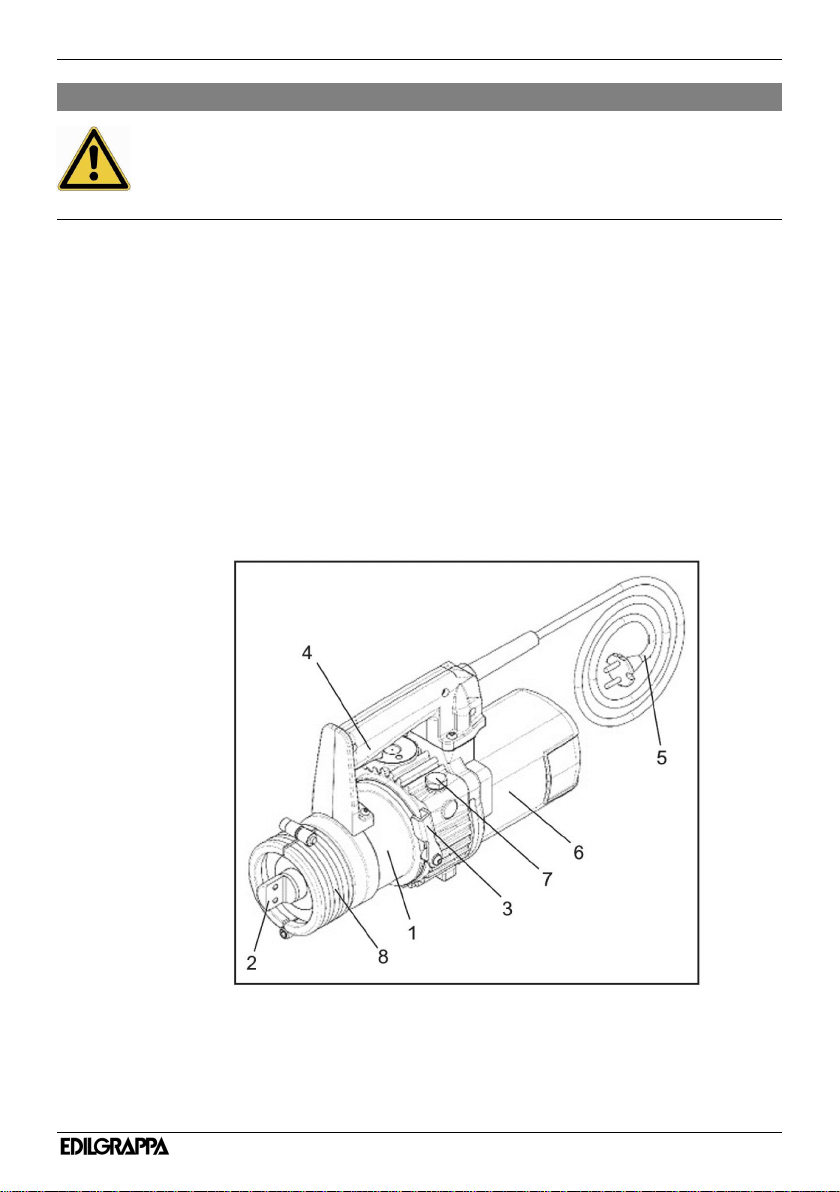
Figure 1 shows the main parts of the equipment, in particular:
1. cylinder with hydraulic components
2. head supporting surface and centring guides
3. release lever or double-acting lever
4. grip with start button
5. electrical connecting cable complete with plug
6. electric motor
7. oil cap
8. head locking ring
5
MU 22N
DANGER
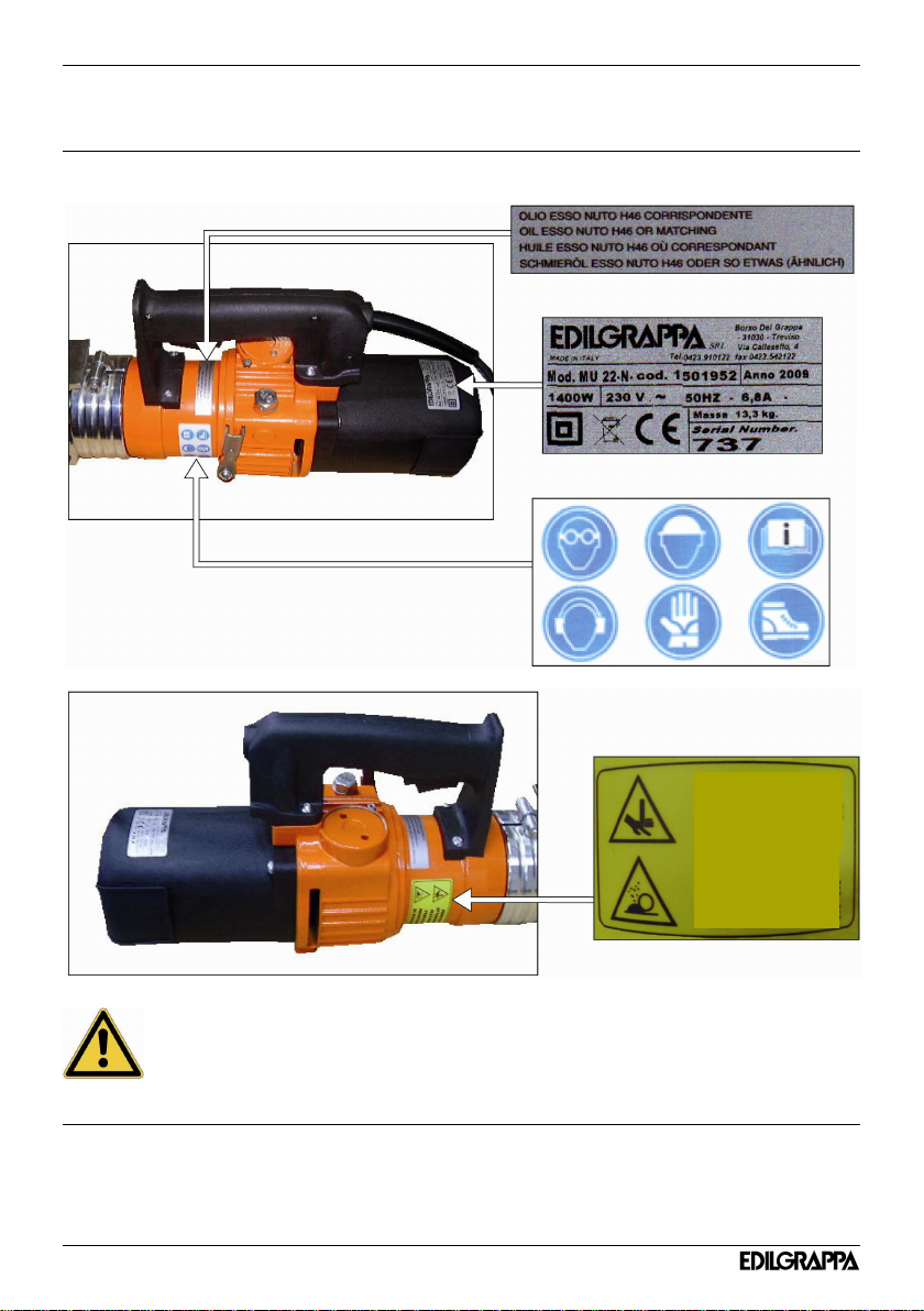
0.02 SAFETY AND DANGER STICKERS - CE PLATE
Position of plate and safety and danger stickers on the machine:
0.03 LIST OF ACCESSORIES INCLUDED IN THE SUPPLY
Observe the warnings on the plates and stickers. Failure to do so could lead to
injury or death. Make sure the plates and stickers are attached and legible. If not,
apply them or request the maker for replacements.
· Case
· General safety rules, Use and maintenance instructions
· Declaration of conformity
· Warranty certificate
· Emergency key
6
BEWARE OF
HANDS
3
DANGER
FLYING
SPLINTERS
 Loading...