

EDI NSM-3E, NEMA TS-1 Operation Manual
THIS MANUAL CONTAINS TECHNICAL INFORMATION FOR THE NSM-3E SERIES
SIGNAL MONITOR UNIT.
REVISION: JULY 2017
pn 888-0003-002
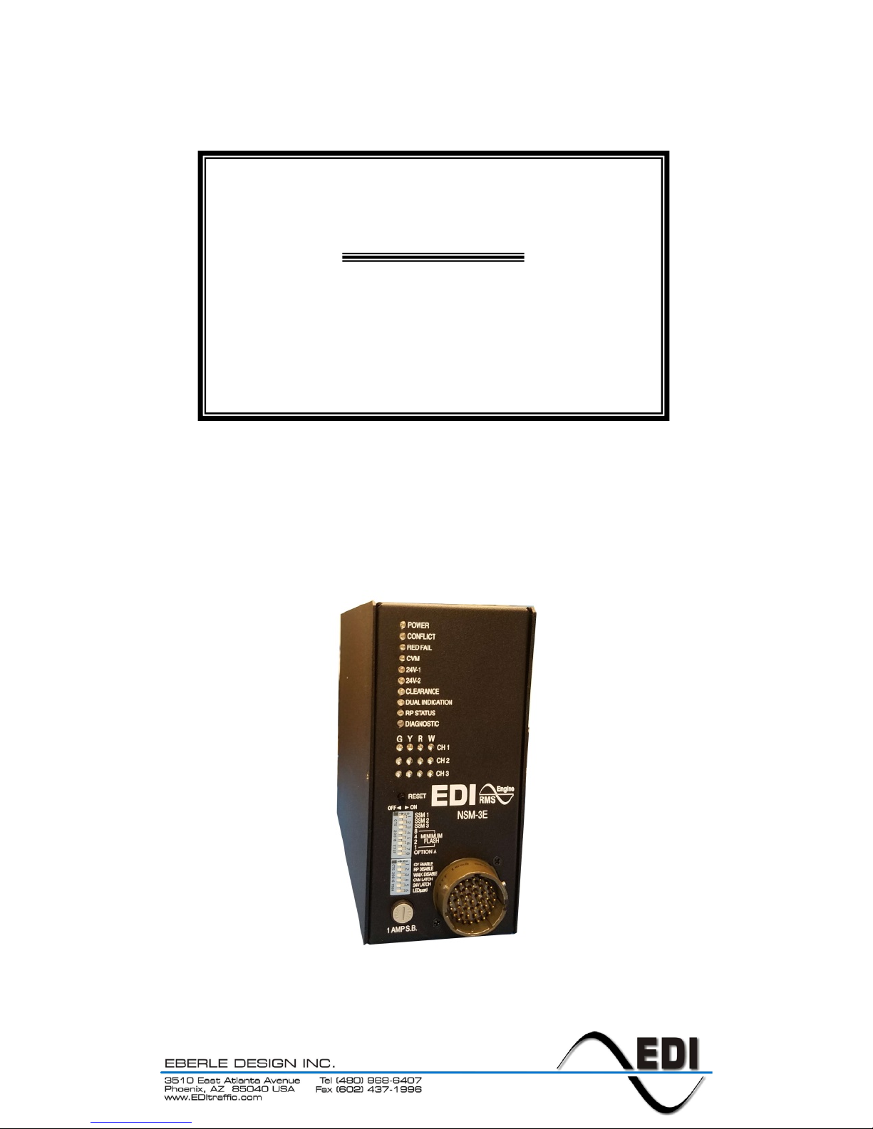
NSM-3E
NEMA TS-1
Enhanced Signal Monitor
Operations Manual

THE NSM-3E SERIES MONITORS ARE DESIGNED AND MANUFACTURED IN THE USA
BY EBERLE DESIGN INC., PHOENIX, ARIZONA, AN ISO 9001:2008 REGISTERED
COMPANY
INFORMATION CONTAINED HEREIN IS PROPRIETARY TECHNICAL INFORMATION
OF EBERLE DESIGN INC. PUBLICATION, REPRODUCTION OR USE IN WHOLE OR
PART IS NOT PERMITTED EXCEPT UNDER TERMS AGREED UPON IN WRITING.
LEDGUARD
®
IS A REGISTERED TRADEMARK OF EBERLE DESIGN INC.
© COPYRIGHT 2017 EDI.
MAINTENANCE NOTE
THIS EBERLE DESIGN INC. AUXILIARY MONITOR UNIT HAS BEEN
CAREFULLY INSPECTED AND TESTED TO ENSURE PROPER
OPERATION. IT IS RECOMMENDED THAT THE AUXILIARY
MONITOR UNIT BE TESTED AT LEAST ANNUALLY TO ENSURE
PROPER OPERATION AND COMPLIANCE WITH FACTORY
SPECIFICATIONS.

Table of Contents
Section 1 Standard Functions ......................................................................................... 1
1.1 Introduction ............................................................................................................ 1
1.2 Conflict Monitoring.................................................................................................. 1
1.3 Red Failure Monitoring ........................................................................................... 1
1.3.1 Walk Disable (Red Monitoring) ...................................................................... 2
1.4 Voltage Monitoring ................................................................................................. 2
1.4.1 Voltage Monitor Fault Latch .......................................................................... 2
1.4.2 CVM Fault Latch ........................................................................................... 2
1.5 AC+ Brown-out / Interruption Detection .................................................................. 2
Section 2 Extended Features ........................................................................................... 3
2.1 Hardware Features................................................................................................. 3
2.2 Dual Indication Monitoring ...................................................................................... 3
2.2.1 GY-Dual Indication Monitoring....................................................................... 3
2.2.2 Walk Disable (Dual Indication Monitoring) ..................................................... 4
2.3 Clearance (Short or Absent Yellow) Monitoring ...................................................... 4
2.4 Recurrent Pulse Detection (RP STATUS) ............................................................... 4
2.5 LEDguard® LED Field Signal Sensing .................................................................... 5
2.6 Non-Volatile Fault Memory ..................................................................................... 5
2.7 Reset Input Detection ............................................................................................. 5
2.8 Display LED Test ................................................................................................... 5
Section 3 Installation ........................................................................................................ 6
3.1 Harnessing Connectors .......................................................................................... 6
3.2 Minimum Flash Dip Switch Programming ............................................................... 6
3.3 SSM Dip Switch Programming ............................................................................... 6
3.4 Option Dip Switch Programming ............................................................................. 6
3.4.1 GY Enable .................................................................................................... 6
3.4.2 RP DISABLE ................................................................................................. 6
3.4.3 WALK DISABLE ............................................................................................ 7
3.4.4 CVM LATCH ................................................................................................. 7
3.4.5 24V LATCH ................................................................................................... 7
3.4.6 LEDguard...................................................................................................... 7
3.4.7 OPTION A ..................................................................................................... 7
Section 4 Front Panel Description ................................................................................... 8
4.1 Status Display ........................................................................................................ 8
4.1.1 POWER Indicator .......................................................................................... 8
4.1.2 CONFLICT Indicator ..................................................................................... 8
4.1.3 RED FAIL Indicator ....................................................................................... 8
4.1.4 CVM Indicator ............................................................................................... 8
4.1.5 24V-1, 24V-2 Voltage Monitor Indicators ....................................................... 8
4.1.6 DIAGNOSTIC Indicator ................................................................................. 8
4.1.7 RP STATUS Indicator ................................................................................... 8
4.1.8 DUAL INDICATION Indicator ........................................................................ 8
4.1.9 CLEARANCE Indicator ................................................................................. 9
4.2 No Fault CHANNEL Display ................................................................................... 9
4.3 Fault CHANNEL Display......................................................................................... 9
4.4 RESET Button ........................................................................................................ 9
Section 5 Specifications .................................................................................................10
5.1 Electrical ...............................................................................................................10
5.1.1 Power Requirements ....................................................................................10
5.1.2 AC Voltage Monitors (Positive or Negative half wave input) .........................10
5.1.3 DC Voltage Monitor ......................................................................................10

5.1.4 Logic Inputs .................................................................................................10
5.2 Timing Functions ...................................................................................................10
5.3 Mechanical ............................................................................................................11
5.4 Environmental .......................................................................................................11
Section 6 Wiring Assignments .......................................................................................12
6.1 NSM-3E Monitor Unit Connector A ........................................................................12

NSM-3E Signal Monitor Unit
Operations Manual
Eberle Design Inc. Page 1
Section 1
Standard Functions
1.1 INTRODUCTION
The NSM-3E Signal Monitor is a device used in a traffic controller assembly to monitor
traffic signals at an intersection for conflicting proceed indications or the absence of voltage
on all of the field signal outputs of a channel caused by malfunctions of the controller, load
switches, or miswiring of the cabinet. The NSM-3E Signal Monitor also provides error
sensing of two +24VDC supplies and the controller power supplies via +24V-1, +24V-2, and
Controller Voltage Monitor (CVM) inputs respectively. This unit is directly interchangeable
with a standard NEMA 3-channel Signal Monitor and meets with or exceeds all
specifications outlined in Chapter 6 (Conflict Monitors) of the National Electrical
Manufacturers Association (NEMA) Standards Publication TS1-1989 R2005, Traffic
Control Systems.
The NSM-3E Signal Monitor is a 3 channel monitor. Each channel has the capability of
monitoring a Green, a Yellow, a Red, and a Walk field signal output at the field terminals.
The NSM-3E Signal Monitor detects the presence of conflicting Green or Yellow or Walk
signals on the AC field terminations between any two or more channels. The Red Enable
input, when active, enables the Red Monitoring and Dual Indication capabilities of the
monitor causing the unit to trigger when it detects the absence of voltage on all four of the
field signal inputs of a channel or more than one input color active simultaneously. The
monitoring circuitry can detect either full wave or positive and negative half-wave field
signal outputs at the specified voltage levels.
When triggered by the detection of a fault condition which exists longer than the minimum
period defined by the NEMA Traffic Control Systems Specifications (TS-1, part 6), the
NSM-3E Signal Monitor will enter the fault mode causing the Output relay to de-energize
and two sets of contacts on the Output relay to transfer. The cabinet assembly should be
wired such that the closure of the signal monitor Output relay contacts will cause an
automatic switching of the field signal outputs from normal operation to flashing operation.
The NSM-3E Signal Monitor will then display the appropriate fault status along with the
proceed indications active at the time of the fault. The NSM-3E Signal Monitor will remain in
this fault mode until a reset command is issued via the front panel RESET button or
External Test Reset Input. The loss of AC+ power will not reset the fault mode of the Output
relay contacts. In the event of AC+ power loss the NSM-3E Signal Monitor will retain the
status of all fault and channel indicators and will display the correct fault and channel status
upon restoration of AC+ power.
1.2 CONFLICT MONITORING
The NSM-3E Signal Monitor is capable of monitoring 3 channels. Each channel monitors a
Red, Yellow, Green, and Walk field signal output at the field terminals. The NSM-3E Signal
Monitor detects the presence of conflicting Green or Yellow or Walk signals on the AC field
terminations between any two or more channels. The monitoring circuitry is capable of
detecting either full wave or positive and negative half-wave field signal outputs at the
specified voltage levels. Upon detecting a Conflict fault, the NSM-3E Signal Monitor will
enter the fault mode, de-energize the Output relay contacts to the Fault position, and
illuminate the CONFLICT indicator.
1.3 RED FAILURE MONITORING
When voltages on all inputs (R, Y, G, and W) to a channel are sensed as inactive for more
than 1000 msec, the NSM-3E Signal Monitor will enter the fault mode, de-energize the
Output relay contacts to the Fault position, and illuminate the RED FAIL indicator. The unit
will remain in the fault mode until the unit is reset by the Reset button or the External Reset
 Loading...