

EDH FlightScope X1 User Manual

Rhein Tech Laboratories, Inc. Client: EDH (South Africa) (Pty) Ltd
360 Herndon Parkway Model: FlightScope X1
Suite 1400 Standards: FCC 15.245/IC RSS-210
Herndon, VA 20170 FCC/IC ID: QXP-SS661/4612A-SS661
http://www.rheintech.com
Report #: 2013032
Appendix K: Manual
Please refer to the following pages.
Page 27 of 33

Doc No. E19-V9365- Issue 2
COPYRIGHT NOTICE:
The information presented in this document may not be copied or reproduced in any form
whatsoever without the prior written consent of EDH. EDH reserves all rights to the information
published this document. Title of the information and any copies thereof shall remain the property of
EDH. No proprietary, copyright, confidential, or other proprietary rights, legend or markings may be
removed from any part of this document.
3D Golf Ball and Club Monitor


FlightScope X1 User Manual
Copyright EDH 2007-2011 E19-V9365 Issue 2
Page i
GENERAL AND SAFETY NOTICES
Summary
The following notices and general safety precautions must be observed during the
operation, service and repair of this equipment. Failure to comply with these precautions
or with warnings elsewhere in the manual violates standards of the design, manufacture
and intended use of the equipment. EDH accepts no liability for failure to comply with
these notices.
Operation of the device in any country may require approval in accordance
with local telecommunications and safety regulations.
Sheltered and Clear Weather Use Only
The equipment has been designed for sheltered or in clear weather use and must not be
used outdoors under rainy conditions.
FCC Statement
Changes or modifications not expressly approved by EDH (South Africa) (Pty) Ltd
could void the user's authority to operate the equipment.
This equipment has been tested and found to comply with the limits for a Class B digital
device, pursuant to part 15 of the FCC rules. These limits are designed to provide
reasonable protection against harmful interference in an office or residential installation.
This equipment generate, uses and can radiate radio frequency energy and, if not
installed and used in accordance with the instructions, may cause harmful interference
to radio communications. However, there is no guarantee that interference will not occur
in a particular installation. If this equipment does cause harmful interference to other
electronic equipment, which can be determined by turning this equipment off and on,
the user is encouraged to try to correct the interference by one or more of the following
measures:
Increase the separation between the equipment causing and experiencing the
interference
Install a radio frequency shield between the equipment causing and experiencing the
interference
Consult your dealer for help
This device complies with Part 15 of the FCC Rules. Operation is subject to the following
two conditions:
This device may not cause harmful interference.
This device must accept any interference received, including interference that may cause
undesired operation.

FlightScope X1 User Manual
E19-V9365 Issue 2 Copyright EDH 2007-2011
Page ii
IC Statement
This device complies with Industry Canada license-exempt RSS standard(s). Operation is
subject to the following two conditions: (1) this device may not cause interference, and
(2) this device must accept any interference, including interference that may cause
undesired operation of the device.
Déclaration IC
Le présent appareil est conforme aux CNR d'Industrie Canada applicables aux appareils
radio exempts de licence. L'exploitation est autorisée aux deux conditions suivantes : (1)
l'appareil ne doit pas produire de brouillage, et (2) l'utilisateur de l'appareil doit accepter
tout brouillage radioélectrique subi, même si le brouillage est susceptible d'en
compromettre le fonctionnement.

FlightScope X1 User Manual
Copyright EDH 2007-2011 E19-V9365 Issue 2
Page iii
Table of Contents
Introduction .............................................................................................. 1
Getting Started - Installation ...................................................................... 3
System Components ............................................................................... 3
Hooking up the cables ............................................................................... 4
USB Cable Connection ......................................................................... 4
Power Supply Connection .................................................................... 4
Placing the Sensor ..................................................................................... 5
Setting up the sensor ................................................................................. 6
Position .............................................................................................. 6
Ground Surface................................................................................... 6
Handle ............................................................................................... 6
Leveling the sensor ............................................................................. 6
Switching On and Off ............................................................................. 7
Switching On ...................................................................................... 7
Switching Off ...................................................................................... 7
Setup Wizard ......................................................................................... 9
Step-by-step procedure ....................................................................... 9
Spin Measurement ................................................................................... 12
Spin measurement methods ............................................................... 12
Spin Measurement ................................................................................... 13
Spin measurement methods ............................................................... 13
Marking and placing a ball for spin measurement ................................. 13
Spin measurement rule: .................................................................... 13
Sensor Status Indicators .......................................................................... 15
Battery Level ........................................ Error! Bookmark not defined.
Sensor Status ................................................................................... 15
Tooltips ............................................................................................ 15
Club Type and Roll/Tilt indicator ......................................................... 15
Sensor Firmware Updating ....................................................................... 17

FlightScope X1 User Manual
E19-V9365 Issue 2 Copyright EDH 2007-2011
Page iv
Technical Capabilities ............................................................................... 21
Balls and Clubs ................................................................................. 21
Measurement zone ............................................................................ 21
Launch velocity ................................................................................. 21
Launch angles ................................................................................... 21
Carry and lateral distances ................................................................. 21
Trajectory height............................................................................... 21
Club head Speed ............................................................................... 21
Spin ................................................................................................. 21
Physical Characteristics ............................................................................ 22
Dimensions (approximate) ................................................................. 22
Mass (sensor) ................................................................................... 22
Environmental Specifications ..................................................................... 22
Ambient temperature: ....................................................................... 22
Ingress protection: ............................................................................ 22
Electrical Characteristics ........................................................................... 22
PC / Mobile Specifications ......................................................................... 23
PCs and Notebooks ........................................................................... 23
Electrical Power Requirements .................................................................. 23
Locations .......................................................................................... 23
Supply Voltage .................................................................................. 23
Earthing ........................................................................................... 23
Requirements for Outdoor Installations ...................................................... 23
Maintenance and Troubleshooting ............................................................. 25
Basic Care ........................................................................................... 25
Rear Panel LED Indicator .......................................................................... 27
Frequently Asked Questions (FAQ) ............................................................ 29
Index ..................................................................................................... 33

I
NTRODUCTION
Congratulations on purchasing FlightScope®, the world’s first-ever 3D
Doppler tracking system for golf.
FlightScope measures how a player hits golf balls, providing information
about the player and the equipment (clubs and balls).
Here are a few examples of what FlightScope can do:
Test clubs and balls to find the best equipment for a player
Measure performance of a player
Golf instruction
Calibrate golf clubs in a player’s bag
Compare performance with other players including top golfers
Evaluate personal progress
Provide instructional and entertaining data about golf shots not known to
most golfers
Research on club and ball performance
As a professional club fitter or golf instructor you can measure the
performance and progress of a player and his/her equipment accurately and
scientifically, find the best equipment fit, and evaluate progress.
As a player, you will be able to go out onto the course knowing your yardage
and shot making capabilities. This will improve your scores and enjoyment of
the game.

Blank Page

G
ETTING STARTED - INSTALLATION
Before FlightScope can be used, the sensor and other hardware and software
must be installed.
System Components
Your X1 system needs a PC/Notebook computer to install and use
FlightScope.
The components included with your system are:
Sensor Unit
USB Cable
AC Adapter
Mains Power Cord
Software on CD
User Manual
Carry Case
The system is intended for use with a PC or notebook computer. See section
on Error! Reference source not found. for details of compatible devices.
H
OOKING UP THE CABLES
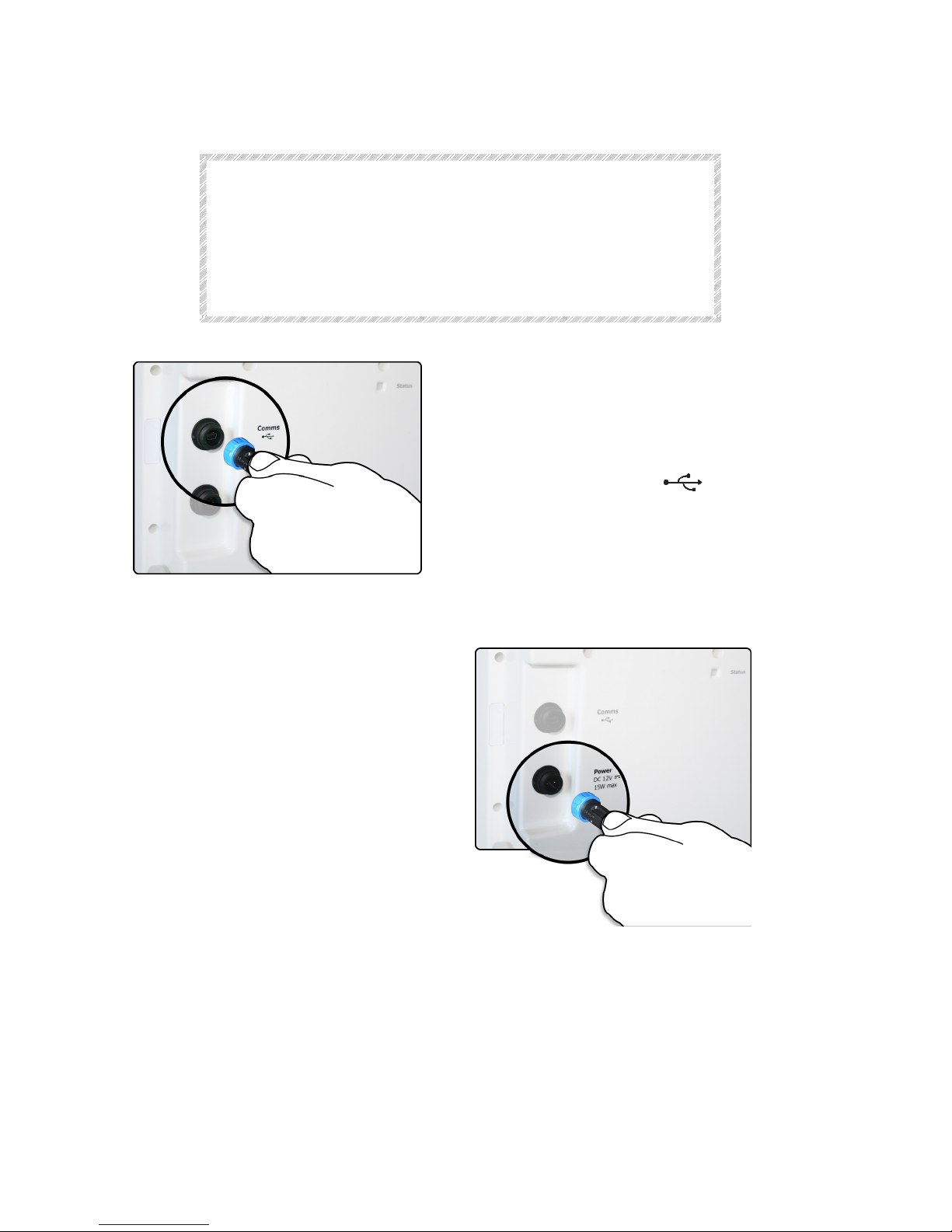
CAUTION
Ensure that connectors are inserted with the
correct orientation.
The connectors are keyed to ensure that they are
inserted correctly. Do not force the connectors
when inserting.
USB Cable Connection
Insert the Communications Cable
(USB) to your PC and connect the
other end to the COMMS connector
marked with the symbol - .
Insert the connector and fasten the
nut lightly.
Power Supply Connection
Insert the AC Adapter connector
into the Power connector on the
rear of the sensor.
The connector is keyed and can
only be inserted one way.
Insert the connector and fasten
the nut lightly.
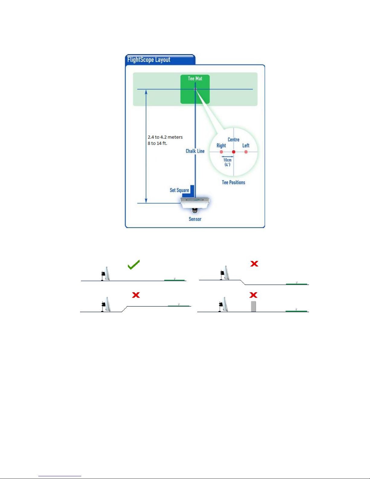
P
LACING THE SENSOR
NOTE
Use FlightScope on a level surface. There must
be no obstructions in front of the sensor.

S
ETTING UP THE SENSOR
Position
The sensor must be placed between 2.4 to 4 meters (8 to 14 ft.) behind the
tee.
Ground Surface
The sensor should be used on a level surface, (grass, carpet, or hard floor).
Handle
CAUTION
The handle is locked in position by spring loaded
plungers. Release the plungers before moving the
handle. Do not force the handle while locked.
Release the handle by sliding the two lock catches inwards to release the
spring loaded pins that lock the handle position. At the same time pull the
handle backwards.
When free, move the handle to the “down” position. The spring loaded pins
will again lock the handle in the down position.
In the down position, the handle acts as the rear support for the sensor.
Leveling the sensor
The sensor should be set up with no roll (sideways angle) and tilted at the
optimum angle of approximately 10 degrees (leaning backwards).
The sensor roll and tilt angles must be manually set by adjusting the feet of
the sensor and/or by modifying the work surface to achieve the correct
sensor angles.
 Loading...