

Page 1
800-782-3762 www.edgewave.com
Hardware Guide
h-Series
Web Filter
Page 2

© 2001 – 2011 EdgeWave Inc. (formerly St. Bernard Software). All rights reserved. The EdgeWave
logo, iPrism and iGuard are trademarks of EdgeWave Inc. All other trademarks and registered
trademarks are hereby acknowledged.
Microsoft and Windows are either registered trademarks or trademarks of Microsoft Corporation in
the United States and/or other countries.
Other product and company names mentioned herein may be the trademarks of their respective
owners.
The iPrism software and its documentation are copyrighted materials. Law prohibits making
unauthorized copies. No part of this software or documentation may be reproduced, transmitted,
transcribed, stored in a retrieval system, or translated into another language without prior permission
of EdgeWave, Inc.
iPrismHW06.520.002
Page 3

Contents
Introduction 1
Related iPrism Documentation 1
iPrism Technical Support 2
Front Panel 2
LEDs and Lights 3
LCD Screen 4
Rear Panel 5
Models 15h and 25h 5
Models 35h, 55h, and 105h 6
Identifying the Cables 7
Installing the iPrism h-Series 7
ii
Page 4

Introduction
iPrism Web Security offers a combination of robust features designed to deliver protection from
Internet-based threats such as malware, botnets, viruses, spyware, circumvention tools,
unauthorized applications and inappropriate content, while helping enforce your acceptable use and
security policies. Your new self-contained, integrated appliance is easy to deploy and manage and is
preloaded with the iPrism software.
This guide describes your iPrism hardware.
Related iPrism Documentation
All documentation is available at:
http://www.edgewave.com/support/web_security/documentation.asp
Document Description
Release Notes Provides up-to-date information on the product, including new features,
improvements, bug fixes, and any known issues. If instructions in the
Release Notes differ from the Installation Guide or Administration Guide,
use the instructions in the Release Notes.
Quick Setup Guide Provides basic installation instructions.
Installation Guide Provides detailed information on installation and initial configuration.
Administration
Guide
Provides detailed configuration and maintenance information for the iPrism
Administrator.
Reporting Guide Explains iPrism report types, features, and delivery options.
Remote Filtering
Client Guide
Provides detailed information on how to configure and set up the iPrism
Remote Filtering Client.
Knowledgebase Searchable and navigable articles provided by Technical Support.
iLearn video tutorials http://www.edgewave.com/support/web_security/recorded_webinars_
ilearn.asp
1
Page 5

iPrism Hardware Guide
iPrism Technical Support
Phone and Email Support
Weekdays, 5:00 am - 5:00 pm Pacific Time
To contact Technical Support online, visit the following URL and fill out the iPrism Support Request
Form:
http://www.edgewave.com/forms/support/web_security.asp
iPrism Phone Numbers
Tel: 1-858-676-5050
Fax: 1-858-676-5055
UK Customers
Tel: +44-20-33554107
EMEA and APAC Customers
Tel: 1-801-903-1751
Front Panel
Figure 1. iPrism Front Panel - Models 15h and 25h
Figure 2. iPrism Front Panel - Models 35h, 55h, and 105h
2
Page 6

iPrism Hardware Guide
LEDs and Lights
The LEDs and lights on the iPrism control panel keep you informed of the system status. The
following LEDs and lights are available on the h-Series:
UID: Unit identifier. Pressing the UID button illuminates an LED on both the
front and rear of the appliance so you can locate the appliance in a large stack
configuration. The LED remains on until the button is pushed a second time.
Another UID button on the rear of the appliance serves the same function.
U: Universal Information LED (models 35h, 55h, and 105h). When this LED
blinks red quickly, it indicates a fan failure; when blinking red slowly, it indicates
a power failure. When on continuously, it indicates an overheat condition,
which may be caused by cables obstructing the airflow in the system or the
ambient room temperature being too warm. Check the routing of the cables
and make sure all fans are present and operating normally. You should also
check to verify that the appliance chassis covers are installed. Finally, verify
that the heatsinks are installed properly (if you need assistance with this,
contact Technical Support). This LED will remain on or flashing as long as the
indicated condition exists.
NIC2:
Model 15h - Flashing indicates network activity on the external interface port.
Models 25h, 35h, 55h, and 105h - Unused.
NIC1:
Model 15h - Flashing indicates network activity on the internal interface port.
Models 25h, 35h, 55h, and 105h - Flashing indicates network activity on the
management port.
HDD: Indicates IDE channel or SATA activity when flashing.
Power: Indicates power is being supplied to the system’s power supply unit(s).
This LED should normally be illuminated when the system is operating.
3
Page 7

iPrism Hardware Guide
Reset: Reboots the system.
Important: Do not press the Reset button until you have shut down
the iPrism from the Exit > Shutdown menu option. This cleanly
terminates the current iPrism services and network connections and
prepares iPrism to be powered down using this button.
Power Button: Used to apply or remove power from the power supply to the
server system. Turning off system power with this button removes the main
power but keeps standby power supplied to the system.
Important: Do not press the Power button until you have shut down
the iPrism using the Exit > Shutdown menu option. This cleanly
terminates the current iPrism services and network connections and
prepares iPrism to be powered down using this button.
LCD Screen
The LCD screen is where you set up the initial configuration for models 35h, 55h, and 105h. It shows
the current status and prompts for input when needed.
Figure 3. LCD Screen
Note: After 3 minutes of no input the LCD screens returns to this default state. Press the
DOWN arrow to return to the previous display.
4
Page 8
iPrism Hardware Guide
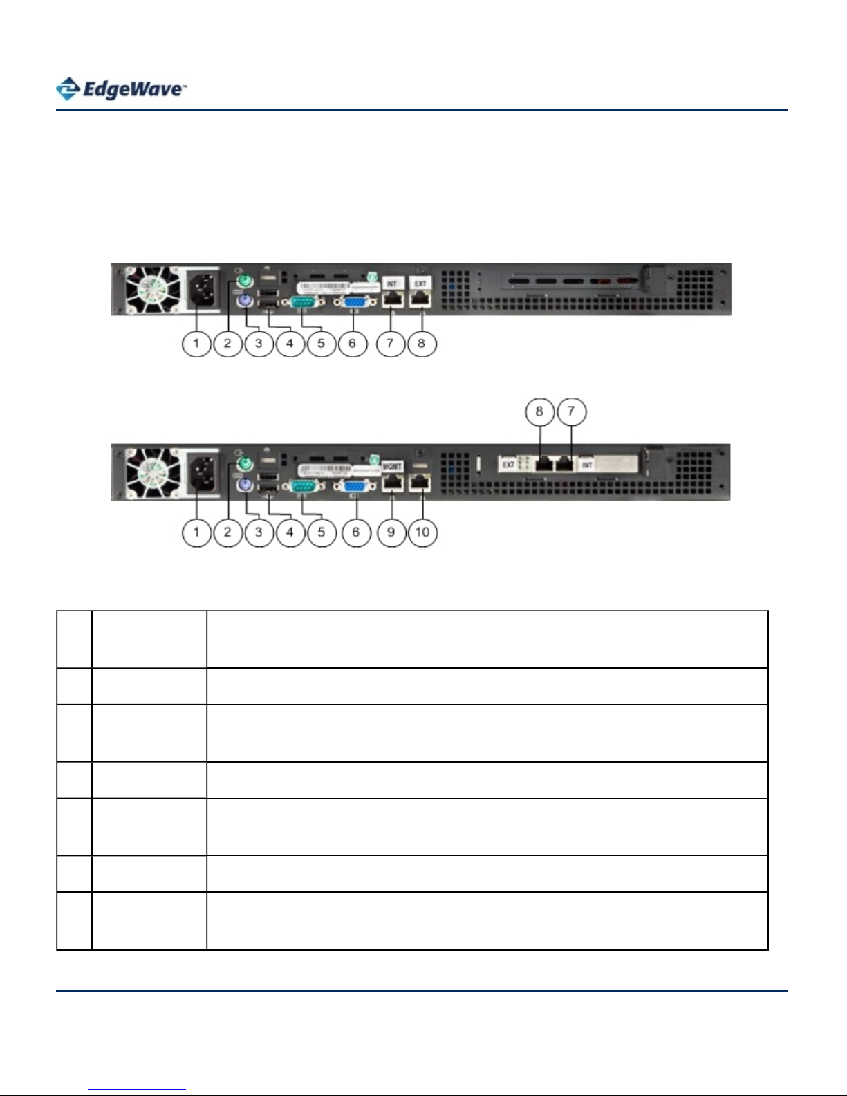
Rear Panel
Models 15h and 25h
Figure 4. iPrism Rear Panel - Model 15h
Figure 5. iPrism Rear Panel - Model 25h
1 Power
connector
Connects power to iPrism (100 – 240 VAC auto-sensing).
2 Mouse port Unused
3 Keyboard
port
Unused
4 USB ports Unused
5 Console port Access to this port is only under the direction of EdgeWave Technical
Support for a specific reason.
6 Video port Unused
7 Internal
interface
This port provides auto-sensing Ethernet connectivity to your internal
network (the network that iPrism will be filtering).
5
Page 9

iPrism Hardware Guide
8 External
interface
This port provides auto-sensing Ethernet connectivity to your external
network (Internet).
9 Management
interface
(LAN1)
This port provides a third auto-sensing 10/100/1000 Mbps Ethernet port
that can be used for out-of-band management of the iPrism.
Note: This is used for advanced configurations only. See the
iPrism
Administration Guide
for more information.
10 Interface Unused
Models 35h, 55h, and 105h
Figure 6. iPrism Rear Panel - Models 35h, 55h, and 105h
1 Power
connectors
These connect power to iPrism (240 VAC auto-sensing).
2 Mouse port Unused
3 Keyboard
port
Unused
4 USB ports Unused
5 Console port Access to this port is only under the direction of EdgeWave Technical
Support for a specific reason.
6 Video port Unused
6
Page 10

iPrism Hardware Guide
7 Management
interface
(LAN1)
This port provides a third auto-sensing 10/100/1000 Mbps Ethernet port
that can be used for out-of-band management of the iPrism.
Note: This is used for advanced configurations only. See the
iPrism
Administration Guide
for more information.
8 Interface Unused
9 Internal
interface
This port provides auto-sensing Ethernet connectivity to your internal
network (the network that iPrism will be filtering).
10 External
interface
This port provides auto-sensing Ethernet connectivity to your external
network (Internet).
Identifying the Cables
The cables shipped with your iPrism can be distinguished by holding one of the cables at each end
so the connectors are oriented the same way. The color-coding of the wires in each connector
indicates the type of cable:
• If the colors are in the same order, it is a standard Ethernet patch cable.
• If the colors are in a different order, it is a crossover cable. The crossover cable’s package is
marked as such.
Installing the iPrism h-Series
1. If you are installing the iPrism in a rack, attach the brackets from the enclosed rack mounting kit
to the iPrism and mount it in a standard rack.
If you need help installing the iPrism in a rack or installing rails, see the Knowledgebase article
“Installing iPrism on a Rack” at:
www.edgewave.com/support/web_security/help_6-4/IP0474.htm.
If you are installing the iPrism on a shelf or desktop, place it on the shelf and make sure that all of
the ventilation holes on the side and back of the unit are clear.
2. Connect the power cable. Do not power the system on at this time.
7
Page 11

iPrism Hardware Guide
3. Connect a network cable from the Internal interface of the iPrism to your internal network. If you
are using DHCP for setup, do this in a location where DHCP is working. See Rear Panel to
locate the Internal interface.
4. Leave the External interface unconnected. See the
iPrism Installation and Configuration Guide
for information on how and when to connect this interface.
5. Leave the Management interface unconnected. Later, if you desire to use a separate network for
management information, you can connect this interface. See the
iPrism Administration Guide
for details.
6. Follow the instructions in the
iPrism Installation and Configuration Guide
for information on how
to complete the installation process and configure your iPrism system.
8
Page 12

Corporate Office
15333 Avenue of Science, San Diego, CA 92128
Phone: 858-676-2277 Fax: 858-676-2299
Toll Free: 800-782-3762 Email: info@edgewave.com
Contact Us
1-800-782-3762
www.edgewave.com
©2011 EdgeWave Inc., All rights reserved.
The EdgeWave and iPrism logos are a trademarks of EdgeWave Inc.
All other trademarks and registered trademarks are hereby acknowledged.
 Loading...