

Edgewater Networks EdgeProtect 7300 Hardware Manual

Edgewater® EdgeProtect™
7300 System Hardware Guide
April 2013 | 7300-000-001B

7300 Hardware Guide
1
Trademark Information
"EDGEWATER NETWORKS and Design, EDGEMARC, EDGEPROTECT, and EDGECONNECT are registered trademarks of Edgewater
Networks, Inc. EDGEWATER NETWORKS and EDGEVIEW are trademarks of Edgewater Networks, Inc."
© 2013 Edgewater Networks Inc. All rights reserved.
Edgewater Networks Inc.
2895 Northwestern Parkway
Santa Clara CA 95051
USA
No part of this document may be reproduced or transmitted in any form or by any means, electronic or mechanical, for any purpose, without the
express written permission of Edgewater Networks Inc. Under the law, reproducing includes translating into another language or format.
As between the parties, Edgewater Networks Inc., retains title to and ownership of all proprietary rights with respect to the software contained
within its products. The software is protected by United States copyright laws and international treaty provision. Therefore, you must treat the
software like any other copyrighted material (e.g., a book or sound recording).
Every effort has been made to ensure that the information in this document is accurate. Edgewater Networks Inc., is not responsible for printing or
clerical errors. Information in this document is subject to change without notice.
7300 Hardware Guide
2
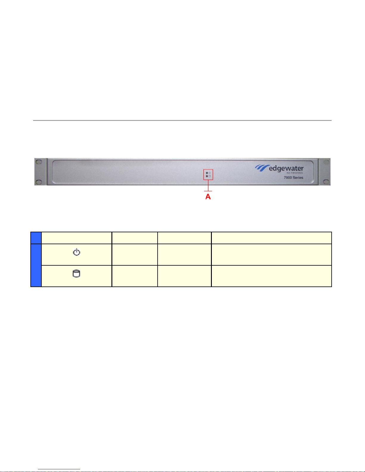
7300 EdgeProtect Series front and back physical connections
Symbol
Function
Color
Signal
A
Power Status
Green
Off – No Power, the system is off
On – Power is good, the system is on
Data Status
Red
Off – No data access to the IDE drive
On – Data is being written to the IDE drive
7300 Hardware Guide
3
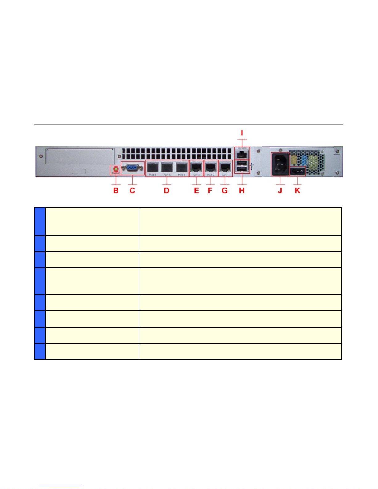
B
Erase
1 Click – No action
2 Clicks - Reset CLI and GUI password – no service interruption
3 Clicks - Restore to factory default and reboots the system
C
VGA
Currently not used
D
Ports 4-5-6
Currently not used
E
Port 3 - Management interface
1 x 10/100/1000 Mbps RJ-45 Ethernet port for optional management network
connectivity, this interface must not be on the same network as the WAN or LAN
subnets. This network cannot be within a subnet contained in a “Route”
statement
F
Port 2 - WAN interface
1 x 10/100/1000 Mbps RJ-45 Ethernet port for connectivity to the WAN or
Internet network connectivity - Default IP: none
G
Port 1 - LAN interface
1 x 10/100/1000 Mbps RJ-45 Ethernet port for LAN network connectivity
Default IP: 192.168.1.1
H
USB
Currently not used
I
Console
1 x RJ-45 console port for management – 9600-N-8-1 NONE for flow control –
RJ-45 to DB9 console cable included in system box

7300 Hardware Guide
4
7300 EdgeProtect Series Ethernet LED’s
J
Input Power Socket
Accepts 3-pin shroud female plug for input power
K
On/Off Switch
System power on/off
Label
Color
Indication
Status
ACK/LINK
Green or
other
On
1: Ethernet port is receiving power
2: Good link between the Ethernet port and the connected switch
Off
1: The adapter and switch are not receiving power
2: No connection between both ends of the network cable, check cable,
replace cable.
Green or
other
Flashing
The adapter is sending and receiving network data. The frequency of the
flashing varies with the amount of data being transferred.
Speed
Yellow
On
ACK/LINK LED must be on. This LED will show the system operating at
1000 Mbps
Green
On
ACK/LINK LED must be on. This LED will show the system operating at
100 Mbps
Off
ACK/LINK LED must be on. This LED will show the system operating at 10
Mbps
 Loading...