

Page 1
DewMaster
Chilled Mirror Hygrometer
OPERATORS MANUAL
19 Brigham Street ● Unit #8 ● Marlborough, MA USA 01752
Tel. [508] 263-5900 ● [800] 276-3729 ● Fax [508] 486-9348
E-mail h2o@edgetech.com ● www.edgetech.com
Page 2

DewMaster
QUICK STARTUP GUIDE – Page 1
STARTUP
1. Connect the DewMaster to the AC Power Line.
2. If the Remote Mounting Kit was ordered, connect Dew Point Sensor Cable
to rear panel and to the Dew Point Sensor.
3. Connect Air Temperature Sensor to rear connector.
4. Install optional Pressure Sensor if required.
5. Wire Analog Outputs and Alarm Relay connections as needed.
6. Connect Serial Port if needed.
7. Install sampling system to Dew Point Sensor ports as needed.
8. Set rear panel Power Switch to ON position.
9. Wait for equilibration and SERVOLOCK indication on Display.
REPROGRAMMING A SETTING
1. Press ENT on Keypad to enter selection menu.
2. Using the UP and DOWN and LEFT and RIGHT arrow keys, scroll to the
desired location of the parameter to be changed.
3. Press ENT again to begin changing the setting. The selected parameter
will flash. Use left and right Arrow keys as required to scroll to the location
of the digit to be changed. Use the numerical keypad to input the change.
4. When programming is completed, press ENT to accept the new setting
and ESC to exit the menu. The KEEP CHANGES? screen will appear.
Press ENT to lock in the change, or ESC to discard the change and return
to the previously programmed value.
Page 3

DewMaster
QUICK STARTUP GUIDE – Page 2
ROUTINE MAINTENANCE (See Maintenance Section)
MIRROR CLEANING
The Automatic Balance Cycle (ABC) greatly minimizes cleaning
requirements of the internal Chilled Mirror Sensor. Contaminants in the air
will gradually build up on the mirror, to the point where manual cleaning is
eventually required. Periods of 90 days between cleanings are typical,
depending on the air source. An indication of CLEAN MIRROR on the
Display, after an ABC Cycle, will tell the user when cleaning is needed.
Use cotton swabs and isopropyl alcohol for mirror cleaning. The manual
shows the mirror location inside the Sensor.
AIR FILTER ELEMENT REPLACEMENT
If a Sampling System is used with the Chilled Mirror Sensor, mirror
cleaning can be minimized by using an in-line air filter in the system.
Depending upon the quantity of contaminants in the incoming air, the Air
Filter element may have to be replaced after a substantial period of
operation. Remove the air filter cover, replace the filter with a new one,
and reassemble.
Page 4

TABLE OF CONTENTS Page
1.0 Quick Startup Card (Removable)
2.0 List of Illustrations 4
3.0 Introduction 5
3.1 General Description 5
3.2 System Overview 5
3.3 Dew Point Sensor 6
3.4 Control Unit 6
3.5 Instrument Options 7
3.5.1 Measured Parameters 7
3.5.2 Analog Outputs 7
3.5.3 Alarm Relay 7
3.5.4 Pressure 7
3.6 Available Accessories 7
3.6.1 Remote Sensor Mounting Kit 7
3.6.2 Available Sample Line Filters 7
3.6.3 Sample Module Kit 7
4.0 Warranty Statement 8
5.0 Quality Statement 9
6.0 N.I.S.T. Traceability 10
7.0 Glossary 11
8.0 Installation 12
8.1 Unpacking 12
8.2 Control Unit Installation 12
8.2.1 Control Unit Placement 12
8.2.2 Wiring Connections 12
8.3 Sensor Setup for Accurate Dew Point Measurements 12
8.3.1 Sample Connections 12
8.3.2 Coolant Connections 13
8.3.3 Sampling Configurations 14
8.3.4 Preheating Sensor and Sample Lines 15
8.3.5 Selection of Components - Low Dew Points 16
8.3.6 Material Moisture Properties 16
8.3.7 Selection of Sample Pumps 17
8.3.8 Recommended Hardware 18
8.3.9 Pressure Measurements 18
Page 5

8.4 Sources of Contamination 18
8.5 Sample Flow Rate 19
9.0 Basic Block Diagram Theory of Operation 21
9.1 Basic Block Diagram Description 22
10.0 Panel Description 23
10.1 Front Panel 23
10.2 Rear Panel 24
11.0 Information Display Functions 26
11.1 Information Displayed 26
12.0 Operating the DewMaster 28
12.1 Information Display 28
12.1.1 Time and Date 28
12.1.2 System Status 28
12.1.3 Main Displays 29
12.1.4 Bar Graph 29
12.2 Programming the DewMaster 29
12.2.1 Keypad Operation 29
12.2.2 Scroll Menu 30
12.2.3 Display Setup 30
12.2.4 Sample Averaging 31
12.2.5 Analog Output 31
12.2.6 ABC Cycle 32
12.2.7 Alarm Relay 32
12.3 Programming the Serial Port 33
12.3.1 Serial Output 33
12.3.2 External Device Connections 33
12.3.3 PC or Terminal Setup 33
12.3.4 RS-232 Commands and Parameters 33
13.0 The Chilled Mirror Dew Point Sensor 39
13.1 Theory of Operation 39
13.2 Mirror Automatic Balance Cycle (ABC) 40
13.3 Care and Maintenance of the Chilled Mirror Sensor 41
14.0 Maintenance 42
14.1 Routine Maintenance 42
2
Page 6

14.2 Mirror Cleaning Schedule 42
14.3 Mirror Cleaning 43
14.4 Understanding ABC and Mirror Messages 43
14.5 Sensor PRT Calibration Check 44
14.5.1 Performing the PRT Calibration Check 44
14.6 Servo Gain Adjustment 44
14.7 Display Contrast Adjustment 45
14.8 Replacing the Fuse 45
14.9 Air Filter Replacement (if used) 45
14.10 Modifying the Analog Outputs 46
15.0 Specifications 47
3
Page 7

2.0 LIST OF ILLUSTRATIONS Page
3-1 DewMaster Chilled Mirror Dew Point Hygrometer 5
8-1 Typical Sampling System 16
8-2 Typical Sample Line Material Characteristics 17
8-3 Flow Corrections for Various Pressures 20
8-4 Flow Corrections for Various Gases 20
9-1 Basic Block Diagram 21
10-1 DewMaster Front Panel 23
10-2 DewMaster Rear Panel 24
11-1 The Information Display 26
12-1 Keypad 30
12-2 Programming the Current Date 31
12-3 Setting the Analog Output Range 31
12-4 Programming the Alarm Relay Setpoint 32
12-5 Locking In the Programming Changes 32
13-1 Chilled Mirror Block Diagram 39
14-1 Cleaning the Mirror 43
14-2 Replacing the Fuse 45
14-3 Analog Mode Switches 46
4
Page 8
3.0 INTRODUCTION
3.1 GENERAL DESCRIPTION
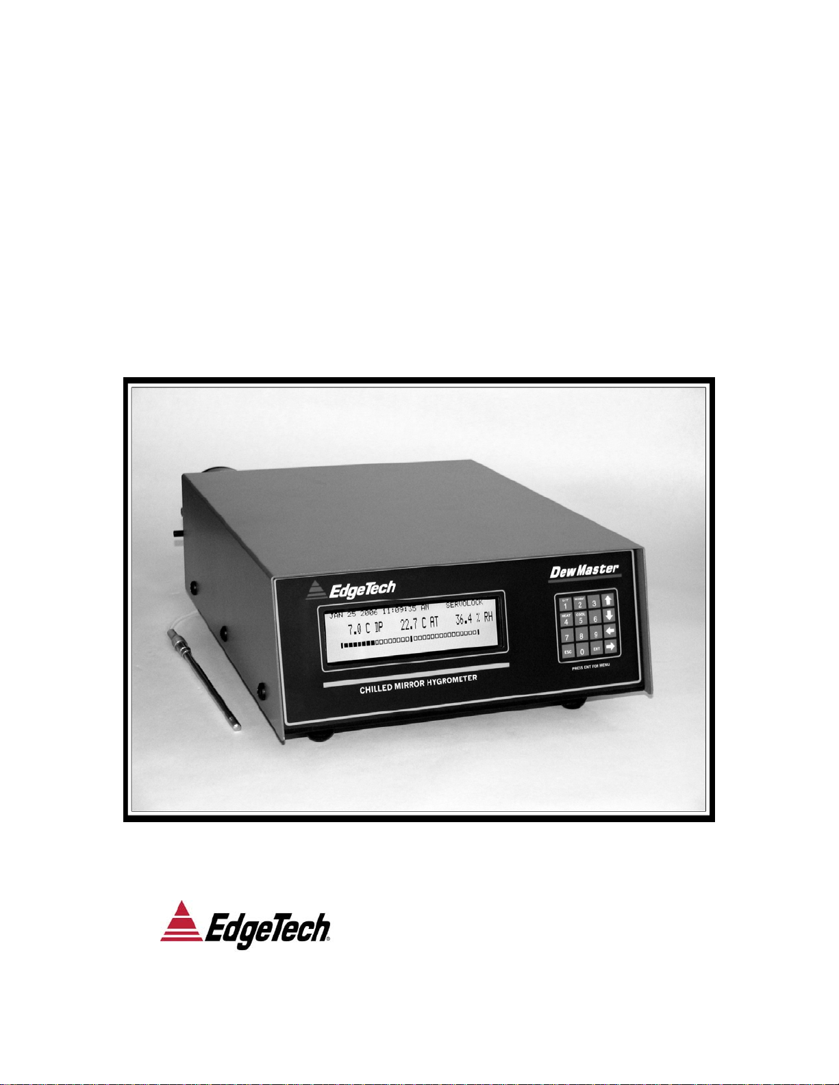
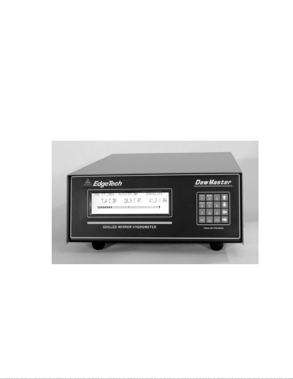
The DewMaster Dew Point Hygrometer (Figure 3-1) is a microprocessor
based, programmable humidity measurement instrument with many
microprocessor controlled features built-in.
Using the highly accurate Optical Chilled Mirror (OCM), primary dew point
measurement technique, the DewMaster was developed for process control
and continuous unattended operation as well as laboratory and research
applications. Three sensors are available, with a depression of either 45°C
(S1 Sensor), 65°C (S2 Sensor), or 95° (S3 Sensor) from an ambient
temperature of 25°C. The system can measure frost points as low as -75°C
(1 PPMv) with the S3 Sensor and auxiliary cooling.
Figure 3-1. DewMaster Chilled Mirror Dew Point Hygrometer
3.2 SYSTEM OVERVIEW
The basic DewMaster system consists of a Control Unit and the S1, S2, or S3
Dew Point Sensor. The Control Unit has a menu driven LCD graphics
display, parameter averaging, Automatic Balance Cycle (ABC), one analog
output, one alarm relay and a RS232C serial port.
Optional features include an Ambient Temperature Probe, three Analog
Outputs, two Form C Alarm Relays, and a live pressure input. The backlit
LCD can display up to three user-selected parameters simultaneously.
5
Page 9

Available readout parameters include Dew Point (C or F), Ambient
Temperature (C or F), PPMv, Wet Bulb, Grains/lb, and Pressure in PSI. All
measured, as well as all calculated values can be displayed as a rolling
average from one to sixteen samples at a one sample-per-second rate. A
hierarchical menu structure driven by “soft keys” provides a user-friendly
method of choosing display options and setting limits and functions from the
front panel.
The Automatic Balance Cycle (ABC) can be set to calibrate the sensor optics
at preset times and intervals or can be initiated manually at any time.
Each analog output is available on the rear panel as 0 to 5 VDC or 4 to 20 mA
and can be set to follow any parameter with individually adjustable high and
low limits. The outputs can be set to TRACK the Dew Point temperature
during the ABC cycle or HOLD the last value prior to the ABC cycle.
The half duplex configured RS232C serial port can be used to set up
functions, control the operation, and output data to a data-recording device.
3.3 DEW POINT SENSOR
The Dew Point sensor has a chromium plated mirror to provide superior
corrosion and abrasion resistance. The sensor is normally mounted on the
instrument rear panel, but it can be mounted remotely up to 75 meters (250
feet) from the instrument by using the optional Remote Cable Mount kit.
Each sensor is equipped with a built-in cooling jacket to extend the
measurement range to lower dew/frost points. The S2 Sensor has a
depression range of 65°C (117°F) at a base temperature of 25°C and the S1
Sensor has a depression of 45° C (81°F). The S3 Sensor has a depression of
95°C (171°F) and comes equipped with two cooling fans in addition to the
cooling jacket. The response time is as high as 1.5°C (2.7°F) per second at
dew points above 0° Celsius. A spin-off cover permits easy access to the
mirror for cleaning without the need of tools or disconnecting sample lines.
3.4 CONTROL UNIT
The DewMaster Control Unit operates entirely under microprocessor control.
State-of-the-art software provides the opportunity to include a flexible,
informational, and user friendly interface. The Information Display and the
Keypad are the only items on the front panel. Setup and operation of the
Control Unit can be programmed via the front panel keypad or the RS-232
serial port.
6
Page 10

3.5 INSTRUMENT OPTIONS
3.5.1 Measured Parameters
The basic unit measures Dew Point. Optional parameters include Ambient
Temperature, RH, PPMV, Gr/lb, and Wetbulb. Consult the factory for
additional parameters.
3.5.2 Analog Outputs
Two additional outputs, for a total of three programmable, 0 - 5 VDC or 4 - 20
mA channels. See the Maintenance section for a description of the internal
programming switches to change from voltage to current outputs.
3.5.3
Alarm Relay
A second relay option provides an additional Form C (SPDT) relay which can
be independently set for a high or low limit on any measured parameter.
When an alarm condition occurs, the relay activates and a flashing message
appears on the display also. The alarm conditions can be set up via the front
panel or the RS232 serial port.
3.5.4 Pressure
The live pressure sensor option enables the measurement of pressuredependent variables such as PPMV or GR/lb. Standard ranges are 0 - 25
PSIA and 0 -100 PSIA. Consult the Factory for the measurement of other
pressure-dependent variables.
3.6 AVAILABLE ACCESSORIES
3.6.1 Remote Sensor Mounting Kit
When it is required to locate the sensor remotely from the control unit, the
optional Remote Mounting Kit must be used. This kit consists of the mounting
hardware, connectors, and cable necessary for locating the sensor remotely.
The standard cable length is 10 ft., however, optional custom lengths up to 75
meters (250 feet) can be ordered.
3.6.2 Available Sample Line Filters
In-line Sample Filter
In-line Coalescing Filter
3.6.3 Sample Module Kit
The Sample Module Kit consists of a free piston vacuum pump and a variable
area flow meter, housed within a NEMA-4X enclosure. The pump can be
supplied to operate on either 115 VAC or 230 VAC ±10%, 50 to 60 Hz input
power.
7
Page 11

4.0 WARRANTY STATEMENT
All equipment manufactured by EdgeTech is warranted against defective
components and workmanship for repair at their plant in Massachusetts,
free of charge, for a period of twelve months. Malfunction due to
improper use is not covered in this warranty and EdgeTech disclaims
any liability for consequential damage resulting from defects in the
performance of the equipment. No product is warranted as being fit for a
particular purpose and there is no warranty of merchantability. This
warranty applies only if (i) the items are used solely under the operating
conditions and in the manner recommended in the instruction manual,
specifications, or other literature; (ii) the items have not been misused or
abused in any manner or repairs attempted thereon; (iii) written notice of
the failure within the warranty period is forwarded to EdgeTech and the
directions received for properly identifying items returned under warranty
are followed; and (iv) the return notice authorizes EdgeTech to examine
and disassemble returned products to the extent EdgeTech deems
necessary to ascertain the cause for failure. The warranties expressed
here are exclusive. There are no other warranties, either expressed or
implied, beyond those set forth here, and EdgeTech does not assume
any other obligation or liability in connection with the sale or use of these
products.
Equipment not manufactured by EdgeTech is supported only to the
extent of the original manufacturer’s warranties
8
Page 12

5.0 EDGETECH’S COMMITMENT TO QUALITY
Thank you for purchasing one of our products. At EdgeTech, it is our
policy to provide cost-effective products and support services that
meet or exceed you requirements, to deliver them on time, and to
continuously look for ways to improve both. We all take great pride in
the products we manufacture.
We want you to be entirely satisfied with your instrument. The
information contained in this manual will get you started. It tells you
what you need to get your equipment up and running, and introduces
its many features.
We always enjoy hearing from the people who use our products. Your
experience with our products is an invaluable source of information
that we can use to continuously improve what we manufacture. We
encourage you to contact or visit us to discuss any issues whatsoever
that relate to our products or your application.
The Employees of EdgeTech
9
Page 13

6.0 N.I.S.T. TRACEABILITY – WHAT DOES IT MEAN?
The DewMaster is certified by Edgetech to be traceable to N.I.S.T., the National
Institute of Standards and Technology (formerly known as the National Bureau of
Standards, or NBS), in Gaithersburg, Maryland, U.S.A. You have received a
Certificate of Calibration with this instrument. What does N.I.S.T. Traceability
mean in terms of this instrument?
The DewMaster measures Dew Point using the Optical Chilled Mirror (OCM)
technique, which provides a primary rather then a secondary measurement of
Dew Point temperature. In addition, Dew Point is a fundamental measurement of
humidity. It is not affected by temperature.
Both the Dew Point temperature and the Air Temperature are measured using
Platinum Resistance Thermometers (PRTs). These devices are coils of nearly
pure platinum, where the rate of change of resistance with temperature is
precisely known. Resistance is accurately measured and is automatically
converted to temperature information within the instrument.
Other parameters, such as Percent Relative Humidity, PPMv, Gr/lb, and Wet
Bulb temperature, are microprocessor-calculated from the directly measured
Dew Point, Temperature, and Pressure (optional) information.
TRACEABILITY:
• 1. The precise platinum resistance thermometers are N.I.S.T. traceable
by the traceable resistance standards maintained by the PRT
manufacturers.
• 2. A multi-point Dew Point calibration is performed on every chilled
mirror sensor, using EdgeTech’s traceable secondary dew point
standard. This instrument, a precise chilled mirror hygrometer, is
periodically sent directly to N.I.S.T. for certification against the USA’s
Dew Point transfer standard, a Two-Pressure Generator.
10
Page 14

7.0 GLOSSARY
ABC: Automatic Balance Control – a method of maintaining accuracy in
the presence of contamination and minimizing maintenance
requirements.
Analog Out A voltage or current that tracks changes in a measured parameter.
AT Air Temperature or Ambient Temperature
Depression The magnitude of available mirror cooling in the chilled mirror
sensor.
DP Dew Point Temperature – the temperature that moisture in the
air just begins to condense on a cooled surface.
Hold Analog output which holds the last humidity reading just before the
ABC cycle.
Hysteresis The tendency of a sensor to give one set of readings when going
up, and a different set of reading when going down.
Mirror A small metallic reflective surface within the dew point sensor.
RH Percent Relative Humidity – the ratio between the actual moisture
content in the chamber and the maximum moisture content if the
chamber air was saturated, at a given air temperature.
RS-232 An accepted industry standard for a serial digital interface.
Serial Port See RS-232.
Servolock
Slew Rate The rate of temperature change of the mirror assembly in the
Track Analog output which follows (tracks) the mirror temperature during
TM
A method of indicating that the system is locked on and tracking the
dew point.
chilled mirror dew point sensor.
the ABC cycle.
11
Page 15

8.0 INSTALLATION
8.1 UNPACKING
Remove the DewMaster Dew Point Hygrometer from its shipping carton and
remove any shipping ties, clamps, and packing material. Save the Certificate
of Calibration shipped with this manual. Locate and save the small box
containing the Cleaner Kit included in the shipping carton. The Model S1, S2
or S3 sensor is normally attached to the DewMaster Control Unit, except
when the optional Remote Mounting Kit is ordered.
8.2 CONTROL UNIT INSTALLATION
8.2.1 CONTROL UNIT PLACEMENT
Install the DewMaster in locations where the ambient temperature will not
exceed the specified ambient temperature range.
Sensors are often specified to have a wider temperature operating range than
the control unit. When the anticipated operating range of the sensor is
expected to be outside the operating temperature range of the instrument, the
sensor should be removed from the instrument and mounted remotely by
means of the optional Remote Mounting Kit.
Always maintain the sensor temperature at least 5°C above the dew point
temperature of the gas being measured. This prevents unwanted
condensation on the inside of the sensor body. In addition, it supports proper
operation of the heat pump control circuit.
8.2.2 WIRING CONNECTIONS
Connect the DewMaster control unit to a grounded, instrument quality power
source of between 95 to 240 VAC, 50 - 60 Hz.
Note: See correct power line fuse values in Specifications section.
You may wish to wire the Analog Output and Alarm Relay connectors.
Connection information is clearly shown on the rear panel of the DewMaster.
Specifications for the Serial Port, and also the Alarm Relay contact ratings,
are in the Specifications section.
8.3 SENSOR SETUP FOR ACCURATE DEW POINT
MEASUREMENTS
8.3.1 SAMPLE CONNECTIONS
A basic requirement of accurate dew point measurements is the proper
design of the gas sampling system. In order to measure the moisture content
of a gas, the sampling system design must consider the effects of the
12
Page 16

materials used, the sample pressure and flow rate, the range of dew points to
be measured, and ambient conditions.
Generally, for dew point temperatures above -18°C, the selection of sample
line materials is not critical. It is only necessary to ensure that the temperature
and pressure ratings are adequate to handle the sample, and that the
connections are gas tight. For dew point temperatures below -18°C, some
attention must be given to the selection of materials in the sample system.
Tubing material, for example, should be hydrophobic in nature, such as
copper or stainless steel. Refer to subsection 8.3.5, Selection of
Components.
Dew point is a measurement of the partial pressure of water vapor in a gas.
Increasing the total pressure of the gas increases the partial pressure of each
of its constituents, raising the dew point. See subsection 8.3.9, Pressure
Measurements.
It is essential that the temperature of sampling components not be allowed to
drop below the dew point temperature of the sample. This prevents
condensation from occurring within the line, causing an erroneous
measurement. Sampling lines and the sensor must be properly preheated
when measuring dew points above ambient temperature. Refer to Preheating
Sensor and Sample Lines, subsection 8.3.4.
In general, the most common problem areas that affect the moisture
measurement of a sampled gas are:
1. Length of the process and/or sample lines.
2. Leaks in the process and/or sample lines.
3. Adsorption or absorption of moisture in the process and sample lines
due to the materials.
4. Excessive elbows, tees, valves, or other fittings used in the sample
lines.
5. Back diffusion of moisture into a pressurized system, particularly at low
dew/frost points.
6. Condensation within the process line and sample line at high dew
points.
7. Diffusion through the sampling materials.
The procedures and parts recommended in this manual should be used only
as a guide in selecting and designing sampling systems. For special or
unique applications, contact an EdgeTech Application Engineer for assistance
in selecting sampling components.
8.3.2 COOLANT CONNECTIONS
For most applications, the Model S1, S2 or S3 sensor does not need cooling
13
Page 17

of the sensor base. Since depression is measured relative to the temperature
of the sensor base, cooling the base will lower the minimum dew point
attainable. The sensor base can be cooled by supplying a liquid coolant to the
integral coolant jacket. The coolant can be ordinary tap water, chilled water,
or a chilled antifreeze solution such as ethylene glycol or methanol. Because
of lower efficiency of the thermoelectric cooler at lower operating
temperatures, depression decreases by 1ºC for every 3ºC of base
temperature decrease. Therefore, the net decrease in minimum dew point if
the base were cooled by 12ºC would be 8ºC.
Coolant flow rates of 0.25 GPM (1 LPM) are adequate, and the coolant
pressure maximum rating is 100 psia (70 kg/cm
2
). Connections to the cooling
jacket of the sensor requires ¼ inch hose and hose clamps.
NOTES:
1. When the coolant temperature is below the dew point temperature of the
ambient atmosphere surrounding the instrument and sensor, condensation
will form both on the surface and inside the sensor. Although this moisture will
not harm the sensor, care should be taken to protect the instrument. In these
cases the sensor should be unfastened from the rear of the instrument and
operated away from the control unit. The optional Remote Mounting Kit allows
the sensor to be located away from the instrument.
2. Please note that the specified depression range of a sensor is not the
same as the actual measurement range. The measurement range is always
a few degrees less at the low end, since the sensor cannot control at a dew
point when it is “bottomed out”, or in the Max Cool condition.
8.3.3 SAMPLING CONFIGURATIONS
A suggested sampling system for use with the DewMaster Dew Point
Hygrometer is shown in Figure 8-1. A portion of the gas line to be sampled is
brought to the hygrometer from a pressure tap, either by using a suitable
vacuum pump or by returning the sample to a lower pressure point. The flow
rate through this main sampling line should be sufficient to allow fast
response times for the sampling system.
A bypass line may be used to increase the main sampling line flow rate
thereby improving the overall response time. It is necessary that the main
sampling line be equipped with a valve for adjusting the sample flow rate.
The hygrometer’s gas sample is obtained from the pressure drop across the
bypass as shown in Figure 8-1. A filter of 0.5 microns at the input to the
sensor would reduce particulate contaminants and decrease mirror cleaning
requirements.
14
Page 18

Several sintered stainless steel types of suitable filters are listed under
Recommended Hardware, in subsection 8.3.8 The filter is considered a
hygroscopic element that will contribute some lag to the sampling system. In
the design of hygrometer sampling systems, minimize the number of
components such as valves, tees, and filters, prior to the Sensor input. The
Sensor output should be connected to a suitable flow measuring device, such
as a rotameter or valve to adjust the flow rate to the recommended range of
0.5 to 5.0 SCFH (14 to 142 LPH).
NOTES:
1. Excessively high sample flow rates may cause a loss in the depression
capability and unstable operation of the system.
2. Considerable savings can be obtained by recognizing that the sample
exhaust lines and related components need not be of as high a quality and
as nonhygrophobic as those prior to the dew point sensor.
3. The gas to be sampled must be furnished to the 1/8-27 NPT male ports on
the sensor. Flow may pass through the sensor in either direction.
4. A sample shut-off valve may be used on the input side of the sensor to
extract the sample. Such a valve is especially useful when opening the
sensor for periodic mirror cleaning, or when working with samples at high
pressures.
8.3.4 PREHEATING SENSOR AND SAMPLE LINES
If the dew point of the gas under measurement is above the ambient
temperature of the installation and sampling lines, both the lines and the
Sensor must be preheated. The sample lines must be installed with heat tape
or another means of maintaining an elevated temperature, so that
condensation will not occur in the route to the sensor. The approach used will
vary widely with the specific nature of the installation, and the user must
ensure that no portion of the sample line is at a temperature lower than the
highest dew point anticipated. If electrical heater lines are used, it is usually
sufficient to connect them to a variable transformer to adjust the heating level.
If the sample lines are long, it may be desirable to wrap them in insulation to
minimize the amount of heat required for preheating. The sensor temperature
must always be maintained at least 10°C above the dew point temperature of
the gas sample. The temperature of the sensor must never exceed +100°C.
Heating the sensor and sample lines above the dew point of the gas sample
does not change the dew point of the sample.
Note: Use of the optional Remote Mounting Kit allows the sensor to
be easily heated.
15
Page 19

EXHAUST
Figure 8 -1. Typical Sampling System
8.3.5 SELECTION OF COMPONENTS AT LOW DEW POINTS
When measuring dew points below -18°C, increased attention to sampling
details must be made as the dew point is lowered. Rubber, neoprene, tygon,
and most plastic tubing are undesirable for use in sample lines. Nonhygroscopic materials such as stainless steel, copper, Impolene, Teflon, or
KEL-F, with a minimum of joints, fittings, and other plumbing, is
recommended. The actual selection of the sample line material should be
based on the degree of permanency of the installation, and the type of fittings
and connections to be used. Generally, stainless steel is preferred for
permanent installations operating at low dew points. On stainless steel lines,
either swage or flare-type fittings can be used. Leaks in the sampling system
must be avoided, particularly for installations operating below atmospheric
pressures, since leakage of ambient air into the sampling system will
seriously offset the readings obtained.
8.3.6 MATERIAL MOISTURE PROPERTIES
All materials will absorb moisture to some extent. The adjacent curves shown
in Figure 8-2 relate typical desorption properties of common sampling line
materials after being exposed to a “wet” gas such as the ambient
atmosphere. The curves illustrate the difficulty of obtaining a fast system
response when switching from a high dew point sample to a low dew point
16
Page 20

sample. Even if the instrument were to respond instantly, the sampling lines
would dictate the overall response.
8.3.7 SELECTION OF SAMPLING PUMPS
Three types of pumps are generally suitable for hygrometric work. For
installations where the sample is not to be returned to the process, the Gas
Manufacturing Co. vane pump is acceptable. This pump offers a reasonably
high degree of reliability and can handle large volumes of air. The vane type
of pump tends to contaminate the sample with minute amounts of pump-wear
by-products (iron, carbon); therefore, it should only be connected on the
output side of the sensor.
0
-10
-20
-30
-40
-45
-50
-55
-60
-65
-70
DEW POINT °F
-75
-80
-85
-90
-95
-100
TIME, MINUTES
STAINLESS
STEEL
20 60 100 140 180 220 260 300
NYLON
POLYETHYLENE
TEFLON
Figure 8 -2. Typical Sample Line Material Response Characteristics
For general-purpose use or for closed-loop sampling at atmospheric
pressure, any one of several types of diaphragm pumps, such as the Neptune
Dynapump, can be used. The Dynapump uses a neoprene diaphragm, and
the pump housing is aluminum.
For most closed-loop sampling, where leak tightness is essential, the welded
bellows type, such as the Metal Bellows MB-21, can be used. These pumps
are available from EdgeTech as well as from their respective manufacturers.
(The optional Sample System Kit uses the Neptune Dynapump Model No. 2.)
17
Page 21

8.3.8 RECOMMENDED HARDWARE
Pumps
Carbon Vane Type:
Gast Mfg. Co. Model 0531-102B-347X (0.6 cfm) or equivalent.
Diaphragm Type:
Neptune Products Dynapump, Model 2 (2.25 cu. in./min.) or equivalent.
Bellows Type:
Metal Bellows Co. Model MB-21 or equivalent.
Filters (General Purpose, In-Line)
Stainless Steel:
NUPRO Model 4F-316, with 60-micron filter element, or equivalent.
Brass:
NUPRO Model 4F, with 60-micron filter element, or equivalent.
Flow Gauges (with valves)
Stainless Steel and Glass:
Brooks Sho-Rate “50” No. 1350-V, or equivalent. range 0.2-4.5 SCFH
Brass and Lucite:
Brooks-Mite No. 2001V, 0.1-4.5 SCFH
Sample Tubing and Recommended Fittings
Stainless Steel, ¼ in.:
Flare, Parker or Swagelok (use SS fittings)
Copper, ¼ in.:
Swagelok or Parker (use brass fittings)
Teflon (or Kel-F) ¼ in.:
Swagelok or Parker Stabilized Polyproplylene
8.3.9 PRESSURE MEASUREMENTS
The dew point temperature of a gas is a measure of the absolute moisture
content of the gas, at a given pressure, regardless of the temperature of the
gas. Most conversion tables for dew point (or frost point), to parts-per-million,
grains-per-pound, etc., are made at atmospheric pressure (14.7 psia or 1.03
kg/cm
2
); therefore, if accurate absolute moisture content measurements are
to be converted to atmospheric-pressure-referenced values, the pressure
must be known. If dew points are to be measured at sample operating
pressures other than atmospheric, the hygrometer sensor should be fitted
with an appropriate pressure gauge.
Caution: The maximum sensor pressure rating is 300 psia, or 21 kg/cm
2
8.4 SOURCES OF CONTAMINATION
Most types of metal tubing contain oil deposits on the interior walls due to the
manufacturing process. This residue must be removed before putting the
18
.
Page 22

lines into service in a gas sampling system. Trichloroethylene or similar
degreasing solvent can be used to clean individual lines and components
before assembly, with a final flushing after assembly. The lines should be
purged dry with air or nitrogen before being placed into service. In addition to
the initial installation, the process itself may constitute a source of
contamination, and, in many applications, these are volatile hydrocarbons.
An excellent fluid for purging and cleaning the instrument and/or the sample
lines is Freon 114. This is a suitable solvent since it is capable of holding
many hydrocarbons in solution, and it is highly volatile, nontoxic, not
explosive, readily available, and will not attack common sampling materials.
8.5 SAMPLE FLOW RATE
When setting sample flow rates at other than 1 atmosphere (1.03 kg/cm
14.7 psia), or when gases other than air are involved, use Figures 8-3 and 8-4
to convert the indicated sample flow rate reading to the actual flow rate.
Figure 8-3 gives the actual flow rate of air at pressures other than 1
atmosphere (14.7 psia). For example, the actual flow rate of air at 30 psia is
3.3 SCFH when the sample flow rate reading is 2.3 SCFH.
Figure 8-4 gives the actual flow rate of six different gases. The actual flow
rate of helium, for example, when the sample flow rate indicates 1.2 SCFH is
3.3 SCFH (at 1 atmosphere). When gas pressures other than 1 atmosphere
are used, use Figure 8-3 to convert the “actual” flow rate reading obtained
from Figure 8-4 to the true flow rate. Using 30 psia, rather than 1 atmosphere
in the helium gas example above, apply the 3.3 SCFH “actual” flow rate
obtained from Figure 8-4 as the Flow Gauge Reading in Figure 8-3, and read
4.8 SCFH as the actual flow rate of helium at 30 psia.
2
or
19
Page 23

5
4
3
2
1
ACTUAL FLOW -
0
0 1 2 3 4
FLOW GAUGE READING - SCFH
Figure 8-3.
for Various Pressures
Flow Corrections Figure 8-4. Flow Corrections
for Various Gases
30 PSIA
20 PSIA
1 ATM
10 PSIA
5 PSIA
5
HYDROGEN
4
3
2
HELIUM
AIR
OXYGEN
ARGON
CARBON
DIOXIDE
1
ACTUAL FLOW -
0 1 2 3 4
FLOW GAUGE READING - SCFH
20
Page 24

9.0 BASIC BLOCK DIAGRAM THEORY OF OPERATION
Air
Temperature
Sensor
Pressure
Sensor
(Optional)
Optics Information
Measurement
Chilled
Mirror
PRT
Measurement
Sensor
Mirror Temp. Control
Heat / Cool
PRT
CPU,
A/D, D/A
Conversion
Analog
Outputs
Alarm
Relays
Serial
Port
Information
Display
DC Power
Supply
Keypad
AC Power In
Figure 9-1. Basic Block Diagram
21
Page 25

9.1 BASIC BLOCK DIAGRAM DESCRIPTION
See the Basic Block Diagram, Figure 9-1.
A one-stage (S1), two-stage (S2), or three-stage (S3) Chilled Mirror Dew Point
Sensor is connected to the DewMaster. Although normally mounted to the rear
panel, a remote mounting kit is also available. Dew Point information, in the form
of platinum resistance thermometer (PRT) measurements, is provided to the
CPU via an A/D converter.
An Air Temperature sensor, also using a PRT measurement, provides
temperature information to the CPU.
An optional pressure sensor may also be used if desired.
The CPU, via Analog-to-Digital and Digital-to-Analog converters, supports the
sensors and receives Dew Point and Temperature data. With these parameters,
it can calculate and display Percent Relative Humidity information. If a Pressure
sensor is added, the CPU also has information to display Parts of Water Vapor
per Million Parts of gas, and other pressure-dependent variables.
The front panel mounted LCD Information Display with its three main displays,
provides a visual interface with the user. It can be used to program such things
as the displayed parameter sequence, alarm setpoints, and analog ranges, in
conjunction with the Keypad. Real Time and Date is shown at the top. Also
shown on the Information Display is a unique profile of the chilled mirror dew
layer, allowing the user to gain insight into the finer points of chilled mirror sensor
operation if desired.
The Keypad, also mounted on the front panel, is used to enter programming
information to the DewMaster. It has soft keys allowing the initiation of heating or
cooling of the dew point sensor mirror, and it can also initiate a manual ABC
Cycle at any time.
Analog Outputs, either 0 to 5 VDC or 4 to 20 mA, (internally selectable) are
provided on the rear panel. One Analog Output is standard, up to three may be
had optionally.
Also provided on the rear panel is a SPDT (Form C) Alarm Relay. A second
Alarm Relay is available as an option.
An RS232C Serial Port is rear panel mounted, allowing the DewMaster to
communicate with a remote terminal or computer. All the programming that can
be done with the Keypad may also be done with the remote device.
22
Page 26

10.0 DESCRIPTION
10.1 FRONT PANEL
1. CONTROL UNIT
2. INFORMATION DISPLAY
3. KEYPAD
Figure 10-1. DewMaster Front Panel
1. Control Unit – The Control Unit contains all the electronics to support
the sensors, allow programming of units and other parameters, display
user information, and allow microprocessor control of the system.
2. Information Display – The LCD Information Display can display up to
three parameters simultaneously, real time and date, operational
status, alarm conditions, sensor mirror condition, and alerts to user to
fault conditions. The Display is backlit to enhance readability.
3. Keypad – The membrane type Keypad allows the user to enter setup
and instrument control information. A Scroll Menu shown on the
Information Display guides the user through the setup procedure. The
setup parameters include Time, Date, Display, Digital Averaging,
Analog Output parameter and scale, ABC start and interval, Alarm
parameter, and Serial Port.
23
Page 27

10.2 REAR PANEL
5. TEMPERATURE
2. POWER SOCKET INPUT
1. ON-OFF 3. FUSE 4. PRESSURE 6. FAN 7. DEW POINT
SWITCH HOLDER INPUT POWER SENSOR (S2)
10. SERIAL
PORT RELAYS OUTPUTS
9. ALARM 8. ANALOG
Figure 10-2. DewMaster Rear Panel
1. ON-OFF Switch – The Power Switch allows convenient control of AC
Power to the DewMaster.
2. Power Socket – The AC Power cord plugs into the Power Socket.
3. Fuse Holder – The Fuse Holder allows convenient replacement of the
AC Power fuse which protects the DewMaster from electrical damage.
4. Pressure Input – This connector allows the user to plug in an optional
live pressure sensor. Pressure-dependent units such as PPMv, as well
as actual pressure may now be read on the front panel Information
Display.
24
Page 28

5. Temperature Input – A Platinum Resistance Thermometer (PRT) may
be connected to this socket, providing readouts of Ambient
Temperature, as well as temperature-dependent calculated
parameters such as Percent Relative Humidity (RH).
6. Fan Power – This socket provides power to optional air-cooled dew
point sensors such as the three-stage Model S3.
7. Dew Point Sensor – A one-stage, two-stage, or three-stage chilled
mirror dew point sensor is normally rear panel mounted as shown. An
optional Remote Mounting Kit is also available.
8. Analog Outputs – One Analog Output, either 0 to 5 VDC or 4 to 20
mA, is available at the rear panel. There is an option for three sets of
Analog Outputs. Each output can be set to track any parameter, and
may be independently scaled using the Scroll Menu or through the
Serial Port.
9. Alarm Relays – One programmable Form C (SPDT) relay is provided
to control external valves or other devices. An option for two Alarm
Relays is available. The alarm setpoints can be set independently for
parameter, value, and high or low activation with the Scroll Menu or
through the Serial Port.
10. Serial Port – The RS-232C Serial Port can be used to remotely
program desired parameters, initiate an ABC Cycle, or output data to a
local or remote terminal, printer, or computer. The data output function
provides the date, time, up to three selected parameters, and system
status to an RS-232C equipped serial device. The data can be sent on
a command from the external device, or sent automatically at
programmed intervals.
25
Page 29

11.0 INFORMATION DISPLAY FUNCTIONS
Figure 11-1. The Information Display
11.1 INFORMATION DISPLAYED
THE LARGE LCD Display mounted on the Front Panel provides the user with all
the information necessary to properly operate the DewMaster. It can be used as
the primary interface with the instrument, showing status of all parameters, and
allowing settings to be easily programmed by using the Keypad.
NOTES:
1. The RS-232 Serial Port, along with a computer or terminal, may
also be remotely used for programming the DewMaster.
2. All programming is in non-volatile memory, so that it is retained
when power is off.
3. The real time clock continues to run when power is off,
maintaining the correct Time and Date information.
26
Page 30

TOP ROW:
DATE The current date
TIME The current time
CONTROL LOOP STATUS Shows Chilled Mirror Control Loop
status
CENTER ROW (MAIN DISPLAY):
AIR TEMPERATURE The actual measured Air Temperature
RELATIVE HUMIDITY The calculated Percent RH
NOTES:
1. The three displays may be used to show any available
parameter.
2. Temperature and Humidity information may be displayed in any
DEW POINT The actual measured Dew Point
desired sequence.
BOTTOM ROW:
BAR GRAPH DISPLAY The Bar Graph displays an actual
picture of the dew layer on the chilled
mirror surface. The right hand vertical
bar indicates the mirror itself, and the
white bars show the actual dew layer.
The layer can be seen to vary in
thickness as the control loop brings the
mirror into control at the dew point.
Then, a thin layer of dew is maintained
on the surface as the mirror temperature
tracks the dew point temperature.
27
Page 31

12.0 OPERATING THE DEWMASTER
In order to operate this instrument, it is assumed that you have read the
INSTALLATION section of this manual, and preliminary tasks have been
done.
These include:
1. The instrument has been connected to a proper AC power
source.
2. If desired, the Analog Outputs, Alarm Relays, and/or Serial
Digital (RS-232) Output has been wired.
3. A dew point sensor sampling system, if needed, has been
installed.
Note: For dry gases, allow sufficient time for the sampling
system to dry out (outgas) before taking measurements. If
moisture content is only a few parts-per-million, it may be
advisable to dry it out overnight.
If you have not checked these points, the INSTALLATION chapter
should be reviewed before proceeding.
Set the rear panel Power Switch to the ON position. The Digital Display
will:
1. Light up
2. Briefly indicate “DEWMASTER by EDGETECH”
3. Go into the normal display mode
12.1 INFORMATION DISPLAY
12.1.1 TIME AND DATE
Real time information is displayed in the upper left corner of the main
Information Display window. This is programmable via the keypad. It is in
non-volatile memory with battery backup, so that the information will
remain correct when instrument power is shut off and later turned on
again.
12.1.2 SYSTEM STATUS
The status of the DewMaster control systems may be seen in the upper
right corner of the Display. When first turned on, it may read HEAT or
STARTUP. At other times, it may read MAX HEAT, or ABC: HEAT, or
ABC: STABLE, or SEEKING DP. After several minutes, the Display will
read SERVOLOCK. This is the normal operating condition, which
28
Page 32

indicates that the system is tracking the Dew Point. Do not take
measurements until the SERVOLOCK indication appears.
12.1.3 MAIN DISPLAYS
Across the center of the Information Display window are the three primary
displays. They may be programmed to read any measurable parameter.
For example, you may wish to display Dew Point, Gas Temperature, and
Pressure (with optional pressure sensor) inside your process. In addition,
the sequence of these displays is independently programmable.
12.1.4 BAR GRAPH
Horizontally across the bottom of the Information Display window is the
Dew Layer Bar Graph. The vertical bar on the far right of the graph
indicates the actual chilled mirror within the dew point sensor. The white
boxes to the left of the mirror bar indicate the thin dew layer maintained on
the mirror while tracking the dew point. In other words, the bars provide a
magnified picture of the mirror condition during sensor operation.
Generally, the dew layer indication will take up approximately 2/3 of the
bar graph.
12.2 PROGRAMMING THE DEWMASTER
12.2.1 KEYPAD OPERATION
DewMaster’s front panel has six soft keys that support user set up and
operation. The label for each key, and it’s function, is described below.
KEY FUNCTION
C/F Toggles the displayed parameters, internal parameters and
RS-232 output between degrees Fahrenheit and Centigrade.
Thus it is important to choose operation in C or F
other set-up activity.
Alarm values and output values are converted from
Fahrenheit to Centigrade when the C/F soft key is pressed.
The analog output level does not change when C/F is
toggled, because ranges are converted.
MABC Starts the Manual ABC cycle. If the DewMaster is already in
an ABC cycle, this key cancels the ABC cycle.
HEAT Turns on/off MAX HEAT. Once this key is pressed, the
sensor is kept in MAX HEAT until the MAX HEAT soft key is
pressed again. In the MAX HEAT mode, SERVOLOCK is
bypassed and the mirror is heated. The upper right section of
the LCD flashes MAN MAX HEAT, and the RS-232 output
before any
29
Page 33

indicates MAX HEAT. During an ABC cycle, MAX HEAT
(MAX COOL) does not function.
NOTE: Turning on MAX HEAT turns off MAX COOL and vice
versa. Both cannot be activated simultaneously.
COOL Turns on/off MAX COOL. The sensor is kept in MAX COOL
until the MAX COOL soft key is pressed again. The upper
right portion of the LCD flashes MAN MAX COOL.
ENT Enter to the SCROLL MENU.
ESC Exit from the SCROLL MENU.
12.2.2 SCROLL MENU
The SCROLL MENU facilitates access
to DISPLAY Setup, ANALOG Setup,
ALARM Setup, ABC Setup, and SERIAL
Setup.
In the SCROLL MENU, use the UP,
DOWN, LEFT and RIGHT arrows to
make your selection and then press the
ENT key. The selected function will
flash on and off and can now be set to
the desired value using the keypad.
Pressing the ENT key will stop the
flashing and another function can be
selected.
Once all values have been set press Figure 12-1. Keypad
the ESC key. The user will be prompted
to accept all changes into non-volatile memory by pressing ENT,
or reject them by pressing ESC. Either choice will return to the main
DISPLAY. When entered in the SCROLL MENU, lack of activity on the
keypad for 30 seconds will cause an exit to the main DISPLAY and no
changes will be saved.
12.2.3 DISPLAY SETUP
Parameters to be viewed on the main DISPLAY: Left, Center, or Right, can be
set in any order. In the SCROLL MENU enter a display box : L, C, or R, and
use the up, down arrows to choose a parameter (or select none). Then press
the ENT key.
30
Page 34

Figure 12-2. Programming the Current Date
12.2.4 SAMPLE AVERAGING (1-16)
With Average set to 1, as each determination is made, it is shown on the
display. With the Average set to 2, the two most recent determinations are
added together and divided by 2, then displayed. With Average set to 16,
the 16 most recent determinations are averaged together for display. If
Average is set to 1, the fastest dynamic response is achieved. However, if
there is some noise or artifact, it will be displayed. If Average is set to 16,
since one determinations are made per second, the most recent 16
seconds of data is averaged to provide each displayed value. If there is
some random noise or small but irrelevant changes in dew point, setting
Average to 16 will smooth out unwanted or irrelevant changes. This can
help avoid false alarms.
12.2.5 ANALOG OUTPUT
Analog Output 1 is located on the rear panel. The SCROLL MENU is used
to assign parameters to the analog output channel. The analog output
(OUT1) is also scaled by selecting the low (LO) and high (HI) range. The
output is factory set at 0-5 VDC. 4-20 ma requires a field modification. To
change it, see Modifying the Analog Output in the Maintenance section.
Figure 12-3. Setting the Analog Output 3 (RH) Range
31
Page 35

12.2.6 ABC CYCLE
The Automatic Balance Cycle (ABC) can be initiated manually at any time,
or started at any specified time of day (ABC START), and repeated at
regular intervals (ABC INTERVAL). The analog output can be programmed
to track or HOLD the parameters during an ABC cycle and the alarm is
automatically disabled. To program a periodic ABC from the SCROLL
MENU the START function must be ON. If ABC HOLD is ON, the analog
and serial outputs will be held at the values just prior to initiating the ABC
cycle. The Display will contain the message “ABC HOLD”. The hold will be
released when the ABC cycle is complete and the instrument has
stabilized back on the dew point.
12.2.7 ALARM RELAY 1
Alarm Relay 1 is located on the rear panel and can be set to operate at
Figure 12-4. Programming the Alarm Relay 1 Setpoint
predetermined parameter limits. From the SCROLL MENU, the relay can
be programmed to be off (OFF), to activate when the low limit is reached
(LOW), or to activate when the high limit is reached (HIGH).
Figure 12-5. Locking In the Programming Changes
32
Page 36

12.3 PROGRAMMING THE SERIAL PORT
12.3.1 SERIAL OUTPUT
The RS232-C serial port is located on the rear panel. To access serial
communication it is necessary to have the Serial Enable on (ON), from the
SCROLL MENU, and also to select the appropriate baud rate. The
DewMaster serial port can be used to operate the unit, program
parameters, or output data to a printer, data terminal, or personal
computer. For bi-directional communications (such as with a PC or
Terminal), a communication or terminal emulation software package is
needed on the PC. There are many inexpensive communication programs
readily available. Two such programs are HyperTerminal in Windows or
PROCOMM PLUS by Quarterdeck/Datastorm Corp.
12.3.2 EXTERNAL DEVICE CONNECTION
Connect an RS-232 cable between the DewMaster 9-pin female D-Type
connector and the RS-232 serial port of the external device. All hardware
handshaking lines are available at the connector; however a 3-wire
XON/XOFF cable is all that is normally required. The serial port is wired as a
DTE device (Data Terminal Equipment); i.e., Transmit (TXD) is pin 2 and
Receive (RXD) is pin 3. Circuit common is pin 5. For connection to a DCE
device (Data Communications Equipment) such as a PC, a direct pin-to-pin
cable can be used. For connection to another DTE device such as a printer, a
null modem adapter is required.
12.3.3 PC OR TERMINAL SETUP
Set the DewMaster to the preferred baud rate via the SCROLL MENU. The
available baud rates are 19.2K, 9600, 4800, 2400, and 1200. For optimum
performance, the baud rate should be set to the highest rate that the
connected device can accommodate reliably. Set up the PC’s communication
program for a baud rate to match the DewMaster. The protocol should be 8
data bits, 1 stop bit, and no parity (N81).
12.3.4 RS-232 COMMANDS AND PARAMETER SETTING
12.3.4.1 GENERAL
Several of the setup and operating features of the DewMaster are available
via the serial port. Commands can be upper or lower case. When any key is
pressed, the DewMaster will respond with “Input: “ and the key that was
pressed “key”. If the command is a single key command, pressing ENTER will
initiate the command. For a two key command, press the second letter and
then the ENTER key to initiate the command.
12.3.4.2 HELP MENU
Once communication has been established, the available commands can be
viewed by accessing the HELP menu.
Type the letter “H”. The display will reply with INPUT: H. Press ENTER and
the HELP menu as shown in Table 12-1 will be displayed on the screen.
33
Page 37

Table 12-1 HELP MENU
COMMANDS EXAMPLE S (Max Entries Shown)
Start a Manual ABC Cycle..................................... AB <CR>
ABC enable toggle ................................................ AE <CR>
ABC Start Time (HH:MM) ..................................... AS <CR> 23:59 <CR>
Analog Hold Toggle (on/off)................................... AH <CR>
ABC Interval (HH:MM).......................................... AI <CR> 23:59 <CR>
Alarm 1 (> or <) (Deg) (param) ............................. AL1 <CR> > 100.0 7<CR>
Alarm 2 (> or <) (Deg) (param) .............................AL2 <CR> < -100.0
7<CR>
Analog 1 Output (Min) (Max) (param) ...............AO1 <CR> -100 100
7<CR>
Analog 2 Output (Min) (Max) (param) ...............AO2 <CR> -100 100
7<CR>
Analog 3 Output (Min) (Max) (param) ...............AO3 <CR> -100 100
7<CR>
Average (Number of Data Points) ......................... AV <CR> 16 <CR>
Enter New Date (MM/DD/YY)................................ D <CR> 12/31/99 <CR>
Latch Alarm1 Toggle ON/OFF............................... L1 <CR>
Latch Alarm2 Toggle ON/OFF............................... L2 <CR>
Max Heat Toggle ON/OFF..................................... MH <CR>
Max Cool Toggle ON/OFF..................................... MC <CR>
Output Interval RS232 (Secs)................................ O <CR> 3600 <CR>
Poll for Parameters................................................P <CR>
Display a Status Report.........................................ST <CR>
Enter New Time (HH:MM:SS) ............................... T <CR> 23:59:59 <CR>
Temperature Units (F, C)....................................... U <CR> C <CR>
Press ENTER to continue…..
Notes:
When a ‘param’(parameter) entry is required, each parameter has a numeric
value as follows: DP (Dew Point) = 1; AT (Ambient Temperature) = 2; RH
(Relative Humidity) = 3; PPMV = 4; Gr/lb = 5; PSIA = 6; PSIG = 7 and Wet
Bulb = 8.
Whenever a setting is changed via the serial port, the serial output times are
recalculated. Input characters are not case sensitive.
34
Page 38

12.3.4.3 START AN ABC CYCLE
This command initiates an ABC cycle at any time. The cycle is the same as a
programmed ABC cycle.
Type the letters “AB” and press the ENTER key.
12.3.4.4 ABC ENABLE
Type “AE” and then ENTER to alternately enable or disable the timed ABC
function. The start time and interval settings will not be changed.
NOTE: Two digits must be used for each entry field.
12.3.4.5 ABC START TIME
Type the letters “AS” and press the ENTER key. Enter the time
“Hours:Minutes” in 24 hr. format, and press the ENTER key.
Examples: “02:00”, is 2:00 AM: “14:30” is 2:30 PM.
12.3.4.6 ABC INTERVAL
Type the letters “AI” and press the ENTER key. Type the time in
“Hours:Minutes” and press the ENTER key.
Example: If the ABC Start Time is 08:00 o’clock in the morning and the ABC
Interval is 02:00, the first ABC cycle for the day would occur at 8:00 AM and
every two hours thereafter.
12.3.4.7 ABC ANALOG HOLD
Typing the letters ‘AH’ will toggle the ABC Hold feature on or off. If ABC Hold
is on, the analog and serial outputs will be held at the values just prior to
initiating the ABC Cycle. The serial output will contain the message “ABC
Hold”. The hold will be released when the ABC Cycle is complete and the
instrument has stabilized back on the dew point.
12.3.4.8 ALARM 1 AND (OPTIONAL) ALARM 2
The alarm relays can be set to operate at predetermined parameter limits.
Each relay can be set as a high or low set point by use of the greater than “>”
and less than “<” symbols.
Each relay can also be independently set to latch when the preset limit is
exceeded. In the latch mode, the alarm will remain active even if the alarm
condition returns to normal. To reset a latched alarm relay, press the
“SETUP” key twice from the main screen. If the latch mode is not set, the
relays will deactivate when the alarm condition is corrected. The front panel
alarm indicators will flash to alert the operator of an alarm that has occurred.
35
Page 39

To enter or change the alarm limits, type the letters “AL1” for alarm 1 or “AL2”
for alarm 2 and press ENTER.
Enter the set point beginning with the > or < symbol followed by a space and
the sign and value of the alarm limit, and the parameter number of the
variable. When completed, press the ENTER key.
Examples:
> +22.3 1 sets relay number one to activate at a level greater than +22.3
degrees dew point (param 1)
< 25.0 3 sets relay number two to activate if RH (param 3) falls below 25%.
12.3.4.9 ALARM 1 AND ALARM 2 LATCHES
The alarms can be set to latch on an alarm condition by typing "L1" for alarm
1 or "L2" for alarm 2.
A latched alarm will not reset itself when the alarm condition is resolved but
requires operator intervention to reset.
The L1 and L2 commands toggle the latch on or off. To reset a latched alarm,
press the ‘SETUP’ key twice.
12.3.4.10 NUMBER OF DATA SAMPLES TO AVERAGE
This command sets the number of data samples to average. Data is sampled
once per second. Therefore, a number of 4 would display a ‘rolling average’
for the last 4 seconds. The limits are 1 to 16 samples.
Type the letters “AV” and press the ENTER key. The DewMaster will respond
with “Enter SETTING =.” Type the two-digit value and press the ENTER key.
12.3.4.11 ANALOG OUTPUT (LOW) (HIGH) (PARAM)
This function sets the 0-5 volt or 4-20 ma (analog) lower and upper output
ranges and the parameter for each of three output channels. The instrument
range is -100 to +100ºC (-148 to +212ºF).
A plus (+) sign is not needed for positive temperature entries, but a minus (-)
sign is necessary.
Type the letters “AO1” for channel one, “AO2” for channel two, or “AO3” for
channel three, and press the ENTER key. Enter the limits with a minus sign
first (if negative), then the lower limit, a space, the positive or negative upper
limit, a space, and the parameter number.
Press the ENTER key to record the values.
36
Page 40

Example:
Entering “-33 45 2” sets a low value of -33º, a high value of +45º, and a
parameter of Ambient Temperature (2). The units, C or F, will be whichever is
active at the time of the setting. If the units are changed later, all affected
parameters will be set to the new units.
12.3.4.12 DATE
Type the letter “D” and then press ENTER.
The DATE format is: MONTH/DAY/YEAR
“01/01/00” = January 1, 2000
“12/31/99” = December 31, 1999
NOTE: Two digits must be used for each entry field and separated by a
backslash character.
12.3.4.13 OUTPUT INTERVAL
This is the interval in seconds between automatic data output transmissions
of the serial data output. The time range is from 0 to 3600 seconds.
Type the letter “O” and press the ENTER key. Enter the desired interval in
seconds and press ENTER.
12.3.4.14 POLL FOR OUTPUT
This command requests the DewMaster to send serial data at any time and is
independent of the automatic interval.
Type the letter “P” and press the “ENTER” key.
12.3.4.15 MANUAL HEAT
This command toggles the Sensor’s heater on or off. It can be initiated at any
time and can be used to clear excessive moisture from the mirror in flooding
situations.
Type the letters “MH” and press the ENTER key. The DewMaster will display
a flashing MAN MAX HEAT and the temperature will rise. To turn off the
MANUAL HEAT mode, enter “MH” again.
12.3.4.16 MANUAL COOL
This command toggles the Sensor’s cooler on or off. It can be used to test the
maximum depression of the Sensor.
Type the letters “MC” and press the ENTER key. The DewMaster will display
a flashing MAN MAX COOL and the temperature will decrease. To turn off the
MANUAL COOL mode, enter “MC” again.
NOTE: After an extended period of time in the cool mode, excess moisture or
frost will form on the mirror. It may be necessary to “Manually Heat” the mirror
to shorten the drying time.
37
Page 41

12.3.4.17 TIME
Type the letter “T” and press ENTER.
The time format is: Hours:Minutes:Seconds. Hours is expressed in 24-hour
military time.
Enter the desired time with colon delimiters:
Examples:
“00:00:00” = 12 midnight
“23:59:59” = 11:59:59 pm
12.3.4.18 UNITS (F,C)
The DewMaster can display temperature in either Degrees C or Degrees F.
The display and RS-232 data will reflect the selection.
Type the letter “U” and press ENTER. Type “C” or “F” and press ENTER.
12.3.4.19 STATUS REPORT
This command gives the user a report of all of the current settings. To get a
status report, do the following.
Type the letters “ST”. The display will show: Input: ST
Press the ENTER key. The following sample status report will display.
DEWMASTER SYSTEM STATUS REPORT
ABC data: State Start Time Interval Hold
ENABLED 0:00:00 2:00 OFF
ALARM data: # Item Type Value Latch State
1 DP HIGH 0.00 C ON READY
2 AT LOW -5.00 C OFF ACTIVATED
ANALOG data: # Item Low High
1 DP -20.00 C 40.00 C
2 DP -40.00 C 60.00 C
3 RH 25 % 75 %
DISPLAY data: Left Middle Right Average
DP PPMV GR 4
SERIAL data: Baud Interval State
9600 1:00 ON
Press ENTER to continue or ESC to return to normal operation.
38
Page 42

13.0 THE CHILLED MIRROR DEW POINT SENSOR
LED Light Source
Chilled Mirror
Thermoelectric Cooler
PRT
Photodetector
Figure 13-1. Chilled Mirror Block Diagram
13.1 THEORY OF OPERATION
Dew Point is defined as the temperature that moisture
just begins to condense
on a surface. The chilled mirror dew point sensor measures this parameter
directly. A highly reflective stainless steel plated mirror is mounted to a solid state
heat pump, or thermoelectric cooler. A light source (LED) is reflected off the
mirror onto an opposing photodetector. The mirror is cooled thermoelectrically to
the temperature at which condensation (dew or frost) first begins to form. This
condensate causes the light from the light source to be scattered, resulting in a
reduction of light as seen by the photodetector. This signal is sent to a servo
amplifier which controls power to the thermoelectric cooler, automatically
controlling the mirror at whatever temperature is required to maintain a very thin
film of water droplets (or frost) on the surface at all times. This is the dew point
(frost point when below 0
o
C) by definition.
Since the mirror surface is always at the dew point, measuring the mirror
temperature provides actual dew point temperature. Temperature data is
39
Page 43

received from a PRT (platinum resistance thermometer) embedded directly
beneath the chilled mirror surface. The PRT is very tightly thermally coupled to
the mirror surface, in order to minimize measurement error.
The advantages of the Chilled Mirror are:
• It provides a primary, as opposed to a secondary measurement of dew
point.
• Measurement is continuous, accurate and repeatable.
• Results are traceable to N.I.S.T., supporting ISO 9000 and military test
requirements.
• No hysteresis.
• No drift.
• Dew point accuracy of +/- 0.2
o
C
These advantages make the Chilled Mirror sensor the technology of choice for
the EdgeTech DewMaster.
13.2 MIRROR AUTOMATIC BALANCE CYCLE (ABC)
The Automatic Balance Cycle is an important electronic feature of the
DewMaster that allows much longer operation of the system without any
maintenance. At least 90 days is typical. As contamination from the air sample
gradually builds up on the mirror surface, an error in the indicated dew point
reading could eventually occur. In order to eliminate this potential source of
error, the system periodically reprograms itself by correcting for the loss in
reflectivity caused by the contaminants on the surface, allowing the mirror to
operate at the actual dew point temperature once again. This is called balancing.
The user should always use the ABC feature, because it greatly minimizes mirror
cleaning requirements.
When you first turn on the DewMaster, the Automatic Balance Cycle is initiated.
It can also be programmed to be initiated automatically with selectable intervals,
or initiated manually at any time by depressing the MABC (Manual Automatic
Balance Cycle) key on the keypad. It can also be initiated remotely by using the
RS-232 port.
The ABC first heats the mirror surface above the dew point, causing the
condensate layer to evaporate, leaving only the contamination on the surface.
The amount of light received from the dry mirror is then measured, and a
correction in the servo loop is made, normalizing the system (balancing) and
compensating for the contaminant layer. The balance cycle only takes a few
minutes, and at the end of that period the mirror resumes tracking the actual dew
point temperature.
40
Page 44

TRACK and HOLD: The Analog Output can be programmed with the keypad to
provide Humidity, Temperature, or optional Pressure information. When Dew
Point is selected, (or Relative Humidity, which is a function of Dew Point and
Temperature), the actual analog value is temporarily incorrect during the ABC.
Since the mirror temperature is constantly measured and defined as the dew
point, the heating of the mirror described above is the one time when the mirror
temperature is intentionally not at the dew point. A keypad programming option
allows the user to have the Analog Output remember the last dew point value just
before the ABC started, and hold that value constant for the few minutes that the
balance cycle requires. It then continues to track the actual real time dew point
temperature (or RH) as before. This is the HOLD option, which may be the best
choice when driving a strip chart recorder or when using a data acquisition
system. If the TRACK option is selected, the resulting positive output pulse on
the analog output during the heating portion of the ABC may be recorded and
used to tell the operator when the cycle occurred.
13.3 CARE AND MAINTENANCE OF THE CHILLED MIRROR SENSOR
Although the ABC greatly minimizes the requirement for mirror cleaning,
eventually the system will have to be shut down and the mirror cleaned. A
CLEAN MIRROR indication displayed at the end of the ABC tells the user when
cleaning is required. See the Maintenance chapter for detailed instructions in
mirror cleaning.
41
Page 45

14.0 MAINTENANCE
pply,
p
CAUTION
Removing the DewMaster Control Unit cover exposes the user to
line operating voltages when the unit is connected to line power.
Only experienced persons should attempt to make adjustments or
tests with the cover removed. If the instrument is plugged in when
performing any circuit adjustments or tests, take extreme care not
to come in contact with the high voltage present around the power
su
the AC line filter, or the rear panel
ower switch.
14.1 ROUTINE MAINTENANCE
To ensure the maximum in accurate and reliable operation of any optical
chilled mirror system, a periodic maintenance program should be established.
14.2 MIRROR CLEANING SCHEDULE
The buildup of contamination on the mirror surface normally occurs very
slowly. Over time, particulates and other matter present in the sample gas
and not captured by filters, build up on the mirror. The result of the buildup of
contaminants on the mirror surface is reduced dry mirror reflectivity and a
change in the optical reference point. The Automatic Balance Cycle (ABC) will
automatically readjust the reference point periodically, but eventually the
adjustment range will be exceeded and a manual cleaning of the mirror may
be necessary. When the contamination becomes too severe to be adjusted
automatically, an error will be displayed at the end of the ABC. Normally,
intervals of 90 days between routine mirror cleanings can be easily achieved.
However, if the sample contaminants are particularly high, more frequent
mirror cleanings may be required. When cleaning is required, clean the mirror
surface and the adjacent optical parts.
When operating with a pressurized
sampling system, be sure to remove
pressure from the Sensor prior to
removing the Sensor cover.
CAUTION!
42
Page 46

14.3 MIRROR CLEANING
To clean the mirror surface in the Sensor:
1. Remove the spin-off cover from the Sensor to expose the mirror.
2. Press the HEAT key on the front panel to heat the mirror and evaporate
any condensate.
3. Cotton swabs and am empty cleaner
bottle are provided in the Cleaning
Kit shipped with the system. Fill the
bottle with isopropyl alcohol,
purchased locally. (We are not
allowed to ship it). Moisten a clean
cotton swab with the alcohol. Wipe
the mirror surface and the optics
surface in a circular motion.
4. After cleaning the mirror surface,
wipe the surfaces dry with a clean
cotton swab.
5. Next, moisten a clean cotton swab Figure 14-1. Cleaning the Mirror
with clean, preferably distilled water
and wipe the mirror and optics areas.
6. Dry these areas thoroughly with a clean, dry cotton swab.
7. Replace the sensor cover.
8. Press the HEAT key again to shut off the heat and allow the mirror to cool.
9. Press the MABC key to balance the optics and return to normal operation.
14.4 UNDERSTANDING THE ABC AND MIRROR MESSAGES
The Automatic Balance Cycle (ABC) is initiated upon instrument turn-on. In
addition, the ABC can be initiated automatically at programmable intervals, or
initiated manually at any time by depressing the MABC (Manual Automatic
Balance Cycle) key on the keypad, or remotely via the RS-232 port.
The ABC begins by heating the mirror to a temperature well above the dew
point to evaporate any dew on the surface. The computer determines that the
mirror is dry and ready to be re-balanced based on a pre-set time interval
AND the stability of the mirror reflectance. The pre-set time interval is
determined by the mirror temperature at the beginning of the cycle. At low
temperatures, greater time is needed to heat the mirror and evaporate the
condensate. If the mirror temperature at the beginning of the cycle is greater
than -20°C, the heat time is a minimum of 1.0 minute. If the temperature is
below -20°C, the heat time is a minimum of 3.0 minutes.
At the end of the heat phase, the computer balances the optical bridge and
control loop and returns to normal operation. If, at the end of an ABC, the
amount of balance adjustment is too large, a flashing “CLEAN MIRROR”
43
Page 47

message will appear on the display and the serial output. See 14.3 above for
detailed mirror cleaning instructions. If the computer finds any other
abnormality in sensor performance during an ABC, a flashing “CHECK
SENSOR” message will appear, in which case the factory should be
contacted.
14.5 SENSOR PRT CALIBRATION CHECK
Platinum Resistance Thermometers (PRTs) are used in the Dew Point
Sensor and Air Temperature Probe. The accuracy has been factory calibrated
and certified. However, if a problem is suspected, the accuracy can be
checked using the PRT Calibration Check procedure.
14.5.1 PERFORMING THE PRT CALIBRATION CHECK
1. A Precision Resistance Decade Box may be used to simulate the PRT in
the Sensor.
2. Remove the top cover, and carefully unplug the large round Dew Point
Sensor plug from its connector.
3. Set the resistance decade box to 100.00 ohms.
4. Using three equal lengths of the same gauge wire, connect pins 4 and 10
of the connector to each other and to one terminal of the decade box.
Connect the other terminal of the decade box to pin 9 of the Sensor
connector.
5. Turn instrument power on. The front panel display should read 00.0°C at
this time.
6. Set the resistance decade box to 119.40 ohms. The display should read
+50.0°C +/- 0.2°C.
7. Set the resistance decade box to 88.22 ohms, a display of -30°C +/-
0.2°C.
8. Once the check has been completed, remove the Resistance Decade Box
and plug the Sensor back into the socket. Reinstall the Control Unit cover.
14.6 SERVO GAIN ADJUSTMENT
The servo gain is adjustable with potentiometer R73 “OPTICS GAIN”.
The adjustment affects the stability of the servo loop, particularly at high dew
points. If the dew point is unstable or appears to oscillate, the gain may need
to be decreased. A sluggish or slow response indicates a higher gain is
required. The GAIN control adjusts the overall gain of the servo control loop.
It is set at the factory to provide stable operation over the range of operation
of the instrument. Before making adjustments to the GAIN control, always
record the factory-set position to aid in returning to the original position at a
later date.
1. Remove the top cover.
2. Rotate R73 clockwise to increase gain or counterclockwise to decrease.
3. Wait about a minute between adjustments to allow the servo loop to
stabilize with the new gain.
44
Page 48

4. Replace the top cover.
14.7 DISPLAY CONTRAST ADJUSTMENT
The display contrast is adjustable with potentiometer R2 “CONTRAST”. The
adjustment can be done in any operating mode.
1. Remove the top cover.
2. Adjust R2 for the desired appearance.
3. Replace the top cover.
14.8 REPLACING THE FUSE
The AC power line fuse is located inside the right-hand portion of the AC Power
socket assembly, in the upper left corner of the rear panel. For access, insert a
small, flat screwdriver into the left side of the fuse holder, and pry the panel open.
Then, pull the inner fuse holder assembly straight out. To close, reinsert the fuse
holder assembly and snap the cover closed.
Figure 14-2a. Opening the Cover Figure 14-2b. Fuse Holder Removed
14.9 AIR FILTER REPLACEMENT
If you are using an external air filter as part of your sampling system,
replacement filter elements should be on hand. Depending upon the quantity of
contaminants present in the incoming air, the filter element may need to be
replaced periodically. A dirty element can cause several problems:
1. A clogged filter will slow down the sampling system response time.
2. The contaminants may be hygroscopic (porous to water molecules),
causing the system to retain moisture and outgas for long periods of
time.
3. If the vacuum pump is downstream of the sensor, a clogged upstream
filter will cause a pressure drop in the sensor sampling system. This
will result in an erroneously low dew point reading.
45
Page 49

14.10 MODIFYING THE ANALOG OUTPUTS
The Analog Output connector is located on the rear panel. Output scaling is
programmed by using the Keypad or through the Serial Port. The user may
select 0 to 5 VDC, 4 to 20 mA, 0 to 20 mA, or 0 to 24 mA for these outputs. The
factory default is 0 to 5 VDC. To change the outputs, it is necessary to remove
the top cover and access three 4-pole DIP switches located inside. The DIP
switches are mounted on the main printed circuit board, near the rear panel.
Figure 14-3. Analog Mode Switches
DIP Switch Configuration:
SWITCH NUMBER
OUTPUT 1 2 3 4
4 - 2O mA
0 - 20 mA
0 - 24 mA
0 – 5 VDC
46
C O C O
O C C O
O O C O
C C O C
Where: O = Open
C = Closed
Page 50

15.0 SPECIFICATIONS
Dew/Frost Point and Ambient Temperature Range
–40* to +60°C (–40 to +140°F) S1 Sensor
–50* to +90°C (–58 to +200°F) S2 Sensor
-75* to +90°C (-103 to +200°F) S3 Sensor
*(Lower dew points may require auxiliary cooling)
Dew/Frost Point and Ambient Temperature Accuracy
±0.2°C (±0.36°F) nominal
Dew/Frost Point and Ambient Temperature Sensors
3-wire Platinum Resistance Thermometer (PRT), 100 ohms at 0°C, nominal
Depression
45°C (113°F), nominal, S1 Sensor
65°C (108°F), nominal, S2 Sensor
95°C (171°F), nominal, S3 Sensor
Auxiliary Coolant Flow Rate (to achieve lower dew points)
1 liter/minute (0.25 gallon/minute) S1,S2 & S3 Sensor - Coolant jacket
standard
Sensor Materials
Chrome, glass, epoxy, anodized aluminum
Remote Sensors
Up to 75 meters (250 feet) S1 and S2 Sensor
Slew Rate
1.5°C (2.7°F)/second max. above 0°C
Repeatability
±0.05°C (0.09°F)
Hysteresis
Negligible
Precision
0.1 degrees C or F
Sample Flow Rate
0.25-2.5 liters/minute (0.5-5.0 SCFH)
Sensor Max. Pressure
0-21 kg/cm2 (0-300 psig) S1,S2 & S3 Sensor
47
Page 51

Operating Temperature
Control Unit: 0 to +50°C (+32 to +122°F)
S1 Sensor: -40 to +60°C (-40 to +110°F)
S2 Sensor: -50 to +100°C(-58 to +212°F)
S3 Sensor: -50 to +100°C(-58 to +212°F)
Display
LCD graphics backlit display
0.25-in. high digits
Keypad
Soft keys for setup and operation: Displayed parameter selection: °C/°F
toggle: Scroll Menu to change time, date: digital averaging: baud ratio:
Manual Auto Balance Cycle initiate: Program Auto Balance Cycle for start
time, interval, output Track/Hold: Maximum Heat toggle: Maximum Cool
toggle: View/change high and low limits for analog outputs: View/change
Alarm parameters, high/low limits, high or low alarms, latched or unlatched
relays.
Analog Outputs (one standard, three optional)
Voltage
0 to +5 VDC, scaleable from -100 to +100ºC (-148 to +212ºF)
±0.5% accuracy
1 K ohms minimum load resistance
Current
4 to 20 ma, scaleable from -100 to +100ºC (-148 to +212ºF)
1K ohms maximum loop resistance
Alarm Relay (one standard, two optional)
One Form C, SPDT alarm relay(s) rated for 3 amps at 24 VDC, 120 VAC
Alarm set point programmable from –100 to + 100ºC (-148 to +212ºF)
Pressure Input (optional)
0 – 25 PSIA, 0-100 PSIA or 0– 250 PSIG standard, other ranges optional
Serial Digital Communication
RS-232C compatible
9-pin D sub-miniature connector (female)
Baud Rates: 1200/2400/4800/9600/19200 Protocol: N81
Output of time, date and dew/frost point at timed intervals
Programming of most keypad functions.
Mirror Condition
Front panel display.
48
Page 52

Auto Balance Control:
Manual initiate of ABC at any time
Automatic ABC with start time and interval programmable from keypad
or RS-232 port.
Outputs programmable for Track or Hold during ABC.
Physical:
Shipping weight:
4.1 kg (9 pounds) with sensor.
Dimensions:
11.1(W) x 4.8 (H) x 16.0 (D) in.
Mounting Configurations:
Desktop (standard)
Power Requirements:
95 to 240 VAC, 50-60 Hz,
75 watts maximum
49
Page 53

Notes
50
 Loading...