

Page 1
RH CAL
Relative Humidity Calibrator
OPERATORS MANUAL
E-mail h2o@edgetechinstruments.com ● www.edgetechinstruments .com
Rev. A March 2011
399 River Road ● Hudson, MA USA 01749
Tel. [508] 263-5900 ● [800] 276-3729 ● Fax [508] 486-9348
Page 2

2
TABLE OF CONTENTS Page
1.0 Quick Startup Card (Removable)
2.0 List of Illustrations 4
3.0 Introduction 5
3.1 General Description 5
3.2 System Overview 5
3.3 Operating Controls 6
4.0 Warranty Information 8
5.0 Edgetech Instruments Inc.’s Commitment to Quality 9
6.0 N.I.S.T. Traceability – What does It Mean? 10
7.0 Glossary 11
8.0 Installation 12
8.1 Unpacking 12
8.2 Wiring Connections 12
8.3 Water Fill 13
8.4 Air Connection (Optional) 13
9.0 Basic Block Diagram Theory of Operation 14
9.1 Basic Block Diagram Description 15
10.0 Panel Description 16
11.0 Information Display Functions 18
11.1 Information Displayed 18
12.0 Operating the RH Calibrator 20
Page 3

3
12.1 System Status 20
12.2 Keypad Operation 21
12.3 Programming the RH-CAL 22
12.4 Calibrating RH Sensors 25
12.5 RS-232 Serial Port Setup 26
13.0 The Chilled Mirror Dew Point Sensor 30
13.1 Theory of Operation 30
13.2 Automatic Balance Cycle 31
13.3 Care and Maintenance of the Sensor 32
14.0 Maintenance 33
14.1 Routine Maintenance 33
14.1.1 Mirror Cleaning Schedule 33
14.1.2 Cleaning the Mirror 33
14.1.3 Dryer Tube Maintenance 34
14.1.4 Filling the Saturator 35
14.1.5 Removing the Front Panel 35
14.2 Replacing the Fuse 36
14.3 Modifying the Analog Output 36
15.0 Specifications 38
Page 4

4
2.0 LIST OF ILLUSTRATIONS Page
3-1 RH Calibrator Panel 5
8-1 Removing Shipping Plug 12
8-2 Filling the Saturator 13
9-1 Basic Block Diagram 14
10-1 Panel Description 16
11-1 The Information Display 18
12-1 Keypad 21
12-2 Changing the RH Setpoint 22
12-3 Changing the AT Setpoint 22
12-4 Selecting Dew or Frost 24
12-5 Locking In the Changes 25
13-1 Chilled Mirror Block Diagram 30
14-1 Cleaning the Mirror 33
14-2 Replacing the Dryer Material 34
14-3 Fuse Location 36
14-4 Analog Mode Switch 36
14-5 DIP Switch Configuration 37
Page 5
5
3.0 INTRODUCTION
3.1 GENERAL DESCRIPTION
The RH CALIBRATOR is a microprocessor based, programmable humidity control
and measurement instrument with many microprocessor controlled features built-in.
Using the NIST Traceable Optical Chilled Mirror primary measurement technique,
the RH CALIBRATOR was developed for precise calibration of RH Sensors and
Transmitters, as well as laboratory and research applications.
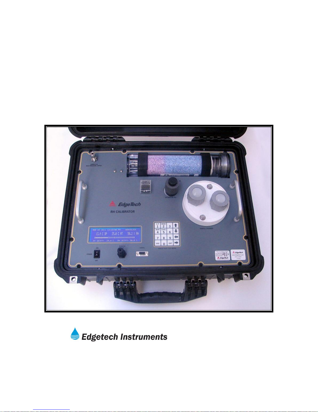
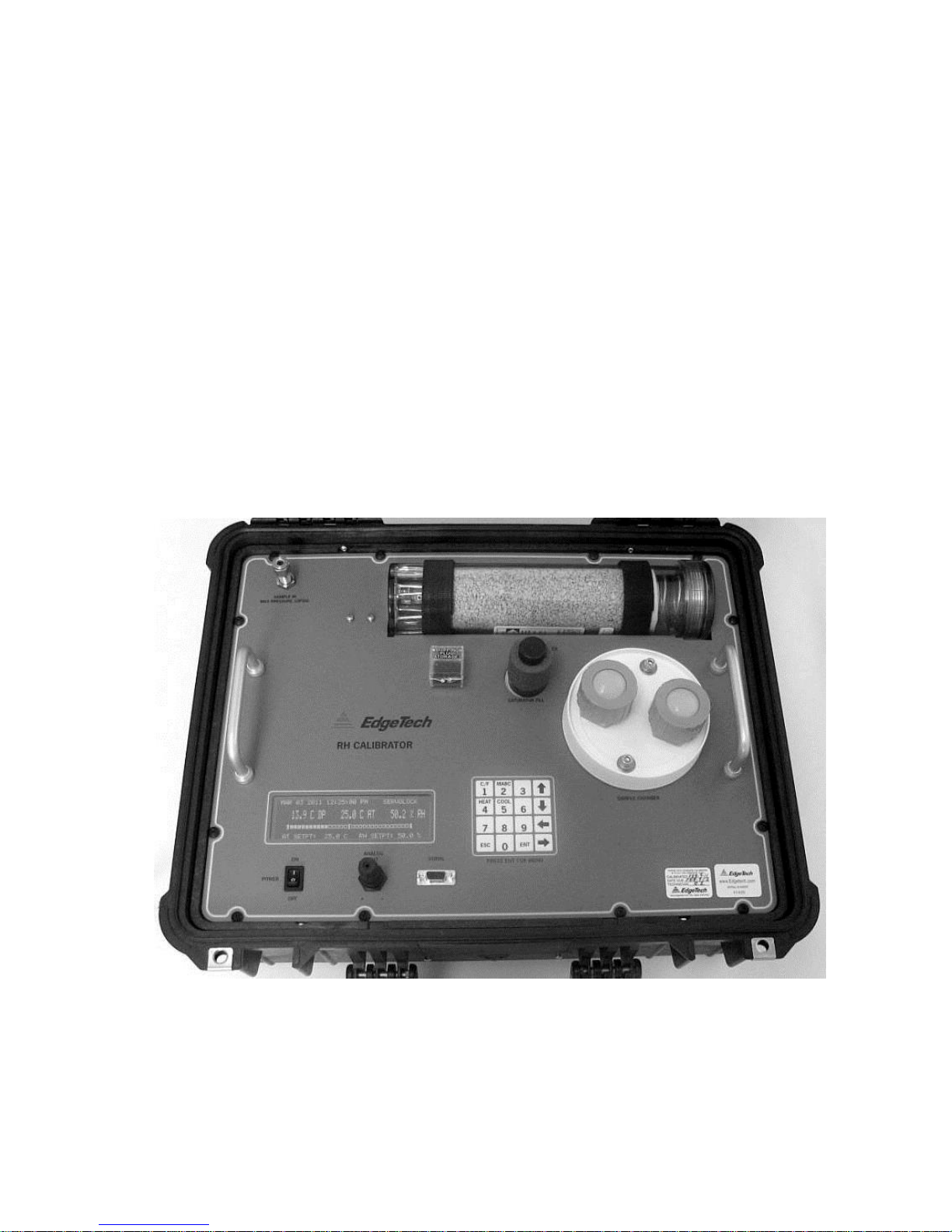
3.2 SYSTEM OVERVIEW
The RH CALIBRATOR has a Test Chamber, a menu driven LCD graphics display,
Automatic Balance Cycle (ABC), a selectable analog output, and an RS-232C serial
port.
Figure 3-1 RH Calibrator Panel
Page 6

6
An Air Temperature Probe and a Type D2 Chilled Mirror Sensor are located in the
Test Chamber. The relative humidity and temperature of the chamber are
programmable from the Scrolling Menu.
The 40 x 8 character backlit LCD displays Dew Point (C or F), Chamber
Temperature (C or F), and Percent Relative Humidity simultaneously.
The Automatic Balance Cycle (ABC) can be set to balance the sensor optics at
preset times and intervals or can be initiated manually at any time.
An analog output is available on the Panel as either 0 to 5VDC or 4 to 20 ma, and it
can be set to follow any parameter with individually programmable high and low
points. The output can be set to Track the selected parameter value during the ABC
cycle or Hold the last value prior to the ABC cycle.
The half duplex configured RS-232C serial port can be used to remotely control the
calibrator operation, and to output data to a data recording device.
3.3 OPERATING CONTROLS
The RH CALIBRATOR operates entirely under microprocessor control. State-of-theart software provides the opportunity to include a flexible, informational, and user
friendly interface. The setup and operation of the control unit can be programmed via
the front panel keypad or the RS-232 serial port.
LCD Graphics Display: Displays three parameters simultaneously, time, date,
operational status, sensor mirror condition, and alerts the user to fault conditions.
When activated from the Scrolling Menu, the AT SETPOINT (chamber
temperature) and the RH SETPOINT (relative humidity), are displayed. The
display of Dew Point may also be selected with the Keyboard.
Keypad: A membrane type keypad allows the user to enter setup and instrument
control information. A Scrolling Menu guides the user through the setup
procedure. The Setup Parameters include RH SETPOINT, AT SETPOINT, time,
date, analog output parameter and scale, ABC start and interval, and serial port
settings.
SERVOLOCK ™: The SERVOLOCK feature continuously displays the servo
control loop status. This is especially useful when the sample dew point is
varying widely or quickly. When SERVOLOCK is displayed, the system is locked
on to and tracking the dew point.
ABC Cycle: The Automatic Balance Cycle checks for proper operation of the
system and re-balances the sensor to compensate for changes in reflectivity of
the mirror due to aging, optics drift, or minor contamination due to impurities in
the sample gas. The on board real time clock permits the user to program the
Page 7

7
ABC cycle to start at any specified time of day and repeat at regularprogrammed intervals. The user can therefore program the ABC cycle to occur at
off-hours such as late at night or early morning when the re-balance will cause
the least interruption of the sampling process. The cycle can also be initiated
manually at any time by a pushbutton on the front panel or via the serial port.
The analog output can be programmed to either TRACK or HOLD the information
during an ABC cycle.
Serial Port: The RS-232C serial port can be used to remotely program setup
parameters, initiate an ABC cycle, or output data to a local or remote terminal,
printer, or computer. The data output function outputs, in ASCII format, the date,
time, three parameters, and system status to any RS232C equipped serial
device. The data can be sent on command from the external device or
automatically at programmed intervals. HELP and STATUS menus can also be
displayed to guide the user.
Analog Output: The analog output, either 0-5 VDC or 4-20 ma, is available at
the Panel terminal connector. The output can be set to track any parameter, and
may be independently scaled via the Scrolling Menu.
Page 8

8
4.0 WARRANTY STATEMENT
All equipment manufactured by Edgetech Instruments Inc. is warranted against
defective components and workmanship for repair at their plant in
Massachusetts, free of charge, for a period of twelve months. Malfunction due
to improper use is not covered in this warranty and Edgetech Instruments Inc.
disclaims any liability for consequential damage resulting from defects in the
performance of the equipment. No product is warranted as being fit for a
particular purpose and there is no warranty of merchantability. This warranty
applies only if (i) the items are used solely under the operating conditions and
in the manner recommended in the instruction manual, specifications, or other
literature; (ii) the items have not been misused or abused in any manner or
repairs attempted thereon; (iii) written notice of the failure within the warranty
period is forwarded to Edgetech Instruments Inc. and the directions received for
properly identifying items returned under warranty are followed; and (iv) the
return notice authorizes Edgetech Instruments Inc. to examine and
disassemble returned products to the extent Edgetech Instruments Inc. deems
necessary to ascertain the cause for failure. The warranties expressed herein
are exclusive. There are no other warranties, either expressed or implied,
beyond those set forth herein, and Edgetech Instruments Inc. does not assume
any other obligation or liability in connection with the sale or use of said
products.
Equipment not manufactured by Edgetech Instruments Inc. is supported only to
the extent of the original manufacturer’s warranties
Page 9

9
5.0 EDGETECH INSTRUMENTS INC.’S COMMITMENT
TO QUALITY
Thank you for purchasing one of our products. At Edgetech Instruments Inc.,
it is our policy to provide cost-effective products and support services that
meet or exceed you requirements, to deliver them on time, and to
continuously look for ways to improve both. We all take great pride in the
products we manufacture.
We want you to be entirely satisfied with your instrument. The information
contained in this manual will get you started. It tells you what you need to
get your equipment up and running, and introduces its many features.
We always enjoy hearing from the people who use our products. Your
experience with our products is an invaluable source of information that we
can use to continuously improve what we manufacture. We encourage you
to contact or visit us to discuss any issues whatsoever that relate to our
products or your application.
The Employees of Edgetech Instruments Inc.
Page 10

10
6.0 N.I.S.T. TRACEABILITY – WHAT DOES IT MEAN?
The RH-CAL, or Relative Humidity Calibrator, is certified by Edgetech Instruments Inc.
to be traceable to N.I.S.T., the National Institute of Standards and Technology (formerly
known as the National Bureau of Standards, or NBS), in Gaithersburg, Maryland, U.S.A.
You have received a Certificate of Calibration with this instrument. What does N.I.S.T.
Traceability mean in terms of the RH-CAL?
The calibration chamber in the RH-CAL can be set by the user to any desired relative
humidity (RH). The instrument measures and controls the chamber RH by measuring
both the air temperature (AT) and the dew point temperature (DP) in the chamber.
Since there is a mathematical relationship between dew point temperature, air
temperature, and relative humidity, a built-in microprocessor can therefore compute the
chamber RH.
Dew Point is a fundamental measurement of humidity. It is not affected by temperature.
In addition, the chilled mirror dew point sensor in your RH-CAL provides a primary
rather then a secondary measurement of dew point temperature.
Both the AT and the DP are measured with Platinum Resistance Thermometers (PRTs).
These devices are coils of nearly pure platinum, where the rate of change of resistance
with temperature is precisely known. Resistance is accurately measured and is
automatically converted to temperature information in the RH-CAL.
TRACEABILITY:
1. The precise platinum thermometers are N.I.S.T. traceable by the traceable
resistance standards maintained by the PRT manufacturers.
2. A multi-point dew point calibration is performed on every RH-CAL chilled
mirror dew point sensor, using Edgetech Instruments Inc.’s traceable secondary
dew point standard. This instrument, a precise chilled mirror hygrometer, is
periodically sent directly to N.I.S.T. for certification against their dew point
transfer standard, a Two-Pressure Generator.
Page 11

11
7.0 GLOSSARY
ABC: Automatic Balance Control – a method of maintaining accuracy in the
presence of contamination and minimizing maintenance requirements.
Analog Out A voltage or current that tracks changes in a parameter.
AT Air Temperature – the temperature inside the test chamber.
Depression The magnitude of available mirror cooling in the chilled mirror sensor.
Desiccant A chemical material which removes moisture from the air sample and
thereby produces very dry air.
DP Dew Point Temperature – the temperature that moisture in the
air just begins to condense on a cooled surface.
Hold Analog output which holds the last humidity reading just before the ABC
cycle.
Hysteresis The tendency of a sensor to give one set of readings when going up, and
a different set of reading when going down.
Mirror A small metallic reflective surface within the dew point sensor.
RH Percent Relative Humidity – the ratio between the actual moisture
content in the chamber and the maximum moisture content if the chamber
air was saturated, at a given air temperature.
RS-232 An accepted industry standard for a serial digital interface.
Saturator A device which brings the air sample to 100% RH.
Serial Port See RS-232.
ServolockTM A method of indicating that the system is locked on and tracking the dew
point.
Slew Rate The rate of temperature change of the mirror assembly in the chilled mirror
dew point sensor.
Track Analog output which follows (tracks) the mirror temperature during the
ABC cycle.
Page 12

12
8.0 INSTALLATION
8.1 UNPACKING
Remove the RH CALIBRATOR from its shipping carton and remove any shipping
ties, clamps, and packing material. Save the Certificate of Calibration shipped
with this manual. Locate and save the Cleaner Kit included in the shipping
carton.
IMPORTANT:
1. Locate the RH-CAL on a flat horizontal surface. Leave a minimum of 6 inches
(15 cm) on both sides for proper air flow.
2. Before first use, unscrew the Saturator Cap and remove the Shipping Plug
(Red Top/Clear Tube) from the small stainless steel Saturator Air Outlet Tube.
Put the Shipping Plug away in a safe place – you may need it later.
Figure 8-1. Remove Shipping Plug
modifications over this range; only the fuse must be changed if changing from a
nominal 115 VAC to 230 VAC.
Note: The correct fuse is installed at the Factory, depending upon the normally
supplied voltage at the shipping location.
Fuse Location: The AC power line fuse is located behind the left side of the
carrying handle, on a printed circuit board mounted inside the carrying case.
Fuse Values:
For U.S. use (and others): For power line voltage between 100 to 150 VAC, the
fuse type is 3A, 3AG, 250VAC, Slo-Blo. For power line voltage between 150 to
240 VAC, the fuse type is 1.5A, 3AG, 250 VAC, Slo-Blo.
For European use: Use Type T fuses. For nominal 230 VAC, the required fuse
value is 1.6A.
NOTE: Whenever the RH CALIBRATOR
is moved, the saturator Shipping Plug
should be installed to prevent water
leakage.
8.2 WIRING CONNECTIONS
Connect the RH CALIBRATOR to a
grounded, instrument quality power
source of between 100 to 240 VAC, 50-60
Hz. There are no jumper or switch setting
Page 13
13
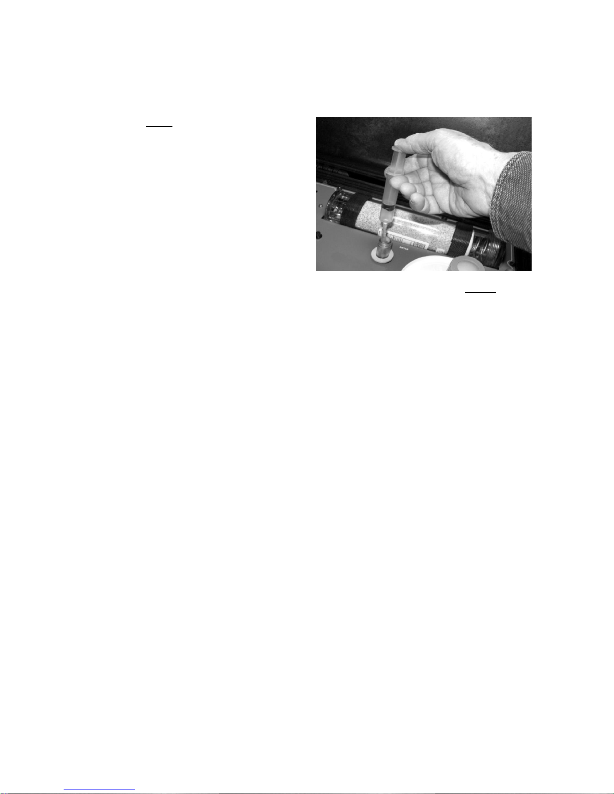
8.3 WATER FILL
Figure 8-2. Filling the Saturator
Note: Only distilled or deionized
water should be used. The
minerals in tap water may
gradually contaminate the
instrument and cause inaccurate
readings.
With power ON, remove the cap
from the clear water reservoir. Using
the supplied syringe, draw water into
the syringe until full. Place the
flexible hose at the end of the
syringe into the opened Saturator fill tube such that the tip extends below the
clear portion of the fill tube, and depress the plunger. Do not fill above the panel
surface. In case of overfill, draw the excess water into the syringe and bring the
water level below the clear portion of the fill tube. Total capacity of the Saturator
is approximately 40 ml (2 – 3 full syringes). Replace the reservoir cap firmly.
8.4 AIR CONNECTION
(Optional)
A ¼ inch compression fitting is mounted on the panel. In normal portable
operation, it is not necessary to connect anything to this port, since room air is
automatically drawn into the calibrator, through the fitting, by the vacuum pump.
If you prefer to use your own source of instrument quality dry air, a ¼ inch line
may be connected. In this mode, the requirement for periodic maintenance of
the desiccant dryer material is eliminated.
Note: Air line pressure must NOT exceed 5 psig.
Page 14

14
9.0 BASIC BLOCK DIAGRAM THEORY OF OPERATION
Figure 9-1. Basic Block Diagram
Page 15

15
9.1 BASIC BLOCK DIAGRAM DESCRIPTION
See the Basic Block Diagram, Figure 9-1.
Room air enters the instrument, via the fitting on the panel. (Note: See the Installation
chapter regarding use of an instrument air line.)
A built-in Vacuum Pump is used to draw in the air sample, and to provide a positive
pressure in the Test Chamber.
The air flow is than divided and sent to a pair of finely matched volumetric Control
Valves. The RH CAL independently modulates the “Dry” and “Wet” valves from full-
open to full-closed, or any points between. The “Wet” valve feeds the heated
Saturator, which has a water fill mounted on the panel. The “Dry” valve feeds the Air
Dryer. When a desired RH setting is programmed into the instrument by the user, the
Control Valves automatically control the proper mixing of the wet and dry air in the
Test Chamber.
A Dew Point (DP) sensor is mounted within the Test Chamber. Control circuits on the
Circuit Board control the sensor mirror temperature, which tracks the Dew Point up
and down as it changes. An Air Temperature (AT) sensor is also installed in the Test
Chamber. Mounted in each of these sensors is a precise platinum thermometer to
provide AT and DP information. When the desired RH is selected by the user, a
microprocessor on the Circuit Board converts this information to Percent Relative
Humidity (RH). The proportion of wet and dry air in the chamber is automatically mixed
to keep it at the programmed RH at all times. In addition, the chamber Air
Temperature(AT) will also be controlled at any point programmed by the user.
An LCD Digital Display is mounted on the panel. It provides all pertinent information to
the operator, and allows programming of all parameters, including real time data. The
Keypad is used to enter desired programming information to the RH CAL.
The Analog Output (selectable 0 to 5 Vdc or 4 to 20 mA) is provided at a connector on
the panel. The Digital Output (RS-232C Serial Port) is also mounted on the panel.
A Power Supply module converts the AC power line voltage to DC to power the
electronic circuits.
Page 16

16
10.0 PANEL DESCRIPTION
2. AIR DRYER
1. AIR INLET 3. WATER FILL TUBE
4. TEST
CHAMBER
5. KEYPAD
9.
INFORMATION
DISPLAY
7. ANALOG OUTPUT 6. DIGITAL OUTPUT
8. ON/OFF SWITCH
Figure 10-1 RH-CAL Panel Description
1. Air Inlet (Sample In) – Brings in room air for use in the system. An
Instrument Air line may also be connected. (1/4 inch compression
fitting)
2. Air Dryer – Removes moisture from incoming air.
3. Water Fill Tube – Supplies water to the temperature controlled Saturator.
Page 17

17
4. Test Chamber – Contains controlled RH and Temperature environment for
calibrating sensors.
5. Keypad – A pressure-sensitive keypad that allows the user to program setpoints
and to control functions.
6. Digital Output – RS-232C serial port for computer communication.
7. Analog Output – Can be programmed to provide information for Dew Point, Air
Temperature, or Percent Relative Humidity. User may select either 0 to 5 VDC
or 4 to 20 ma.
8. ON/OFF Switch – Turns Power ON or OFF.
9. Information Display – Reads out all system information, such as Set Points and
actual Test Chamber conditions.
ITEMS NOT SHOWN:
Air Outlet – on right rear of carrying case (1/4 inch compression fitting).
AC Power Input Socket and Fuse Holder – on left side of carrying case.
Page 18

18
11.0 INFORMATION DISPLAY FUNCTIONS
Figure 11-1. The Information Display
11.1 INFORMATION DISPLAYED
The large LCD Display mounted on the Panel provides the user with all the information
necessary to properly operate the RH-CAL. It can be used as the primary interface with
the instrument, showing status of all parameters, and allowing calibration points to be
easily programmed.
NOTES:
1. The RS-232 Serial Port, along with a computer or terminal, may also
be remotely used for the same purpose.
2. All programming is in non-volatile memory, so that it is retained
when Power is off.
TOP ROW:
DATE The Current Date
TIME The Current Time
CONTROL LOOP STATUS Shows Chilled Mirror Control Loop
condition
CENTER ROW (MAIN DISPLAY):
DEW POINT The actual Chamber Dew Point
AIR TEMPERATURE The actual Chamber Temp.
RELATIVE HUMIDITY The actual %RH in the Chamber
Page 19

19
Note: The above three parameters may be programmed to be
displayed in any desired sequence.
S_HEAT DISPLAY: Cycles on and off to show when
power is applied to Saturator
heater.
BAR GRAPH DISPLAY: The Bar Graph displays a picture of the
dew layer on the chilled mirror surface.
The right hand vertical bar indicates the
mirror itself, and the white bars show the
actual dew layer. The layer can be seen
to vary in thickness as the control loop
brings the mirror into control, and then
maintains a thin layer of dew as the
mirror temperature tracks the dew point
temperature.
BOTTOM ROW:
AIR TEMP. SETPOINT The programmable AT setting
RH SETPOINT The programmable RH setting
Page 20

20
12.0 OPERATING THE RH CALIBRATOR
In order to operate this instrument, it is assumed that you have read the
INSTALLATION section of this manual, and preliminary tasks have been done.
These include:
1. The Shipping Plug has been removed from the Saturator Fill Tube.
2. The Saturator has been properly filled with water.
3. The instrument has been connected to the AC power source.
4. If desired, the Analog and/or Serial Digital (RS-232) Output has been wired.
If not, the INSTALLATION chapter should be reviewed before proceeding.
Turn the Power Switch to the ON position. The small adjacent indicator lamp will
light, and the Digital Display will: (1) light up; (2) briefly indicate RH
CALIBRATOR by EDGETECH INSTRUMENTS INC.; and (3) go into the normal
display mode. A hum will be heard, indicating that the fans and vacuum pump
are operating.
12.1 SYSTEM STATUS
The status of the RH-CAL control systems may be seen in the upper right corner
of the Display. When first turned on, it will read STARTUP. At other times, it
may read MAX HEAT, or ABC: HEAT, or ABC: STABLE, or SEEKING DP. After
several minutes, the Display will read SERVOLOCK. This indicates that the
system is tracking the Dew Point, and that the RH condition in the chamber is
stabilizing.
The chamber should only be used for calibration when the display reads
SERVOLOCK and the RH reading has stopped changing and reads the setpoint
value +/- the RH-CAL accuracy specification.
12.2 KEYPAD OPERATION
The RH CALIBRATOR Panel has six keys that support user set up and
operation. The label for each key, and its function, is described below.
Key Function
C/F Toggles the displayed parameters, internal parameters and RS-232 output
between degrees Fahrenheit and Centigrade. Output values are also converted
Page 21

21
from Fahrenheit to Centigrade when the C/F key is pressed. The analog output
level does not change when C/F is toggled, because ranges are converted.
MABC Starts the Manual ABC cycle. If the RH
CALIBRATOR is already in an ABC
cycle, this key cancels the ABC cycle.
HEAT Turns on/off MAN MAX HEAT. Once this
key is pressed, the sensor is kept in
MAN MAX HEAT until the MAN MAX
HEAT key is pressed again. In MAN
MAX HEAT, the SERVOLOCK is
bypassed and the mirror is heated. The
upper right section of the LCD flashes
MAN MAX HEAT, and the RS-232 output
indicates MAX HEAT. During an ABC
cycle, MAX HEAT (MAX COOL) does not
function.
Figure 12-1. Keypad
NOTE: Turning on MAX HEAT turns off MAX
COOL and vice versa. Both
cannot be activated simultaneously.
COOL Turns on/off MAX COOL. The sensor is kept in MAX COOL until the MAX
COOL key is pressed again. The upper right portion of the LCD flashes MAN
MAX COOL.
ENT Enter the SCROLLING MENU.
The SCROLLING MENU PROVIDES access to RH SETPOINT, AT
SETPOINT, ANALOG OUTPUT, ABC, and SERIAL setup functions.
In the SCROLLING MENU use THE UP, DOWN, LEFT and RIGHT arrows to
highlight a selection and press ENT to enable changes. The selected function
will flash on and off and can now be set to the desired value using the keypad.
ESC Exit from the SCROLLING MENU.
Page 22

22
12.3 PROGRAMMING THE RH-CAL
RH SETPOINT: The relative humidity of the sample chamber can be set from 5 to 95%
and will operate automatically at the factory default setting unless reprogrammed. The
RH SETPOINT will appear in the lower portion of the main display. To change the
setting, press ENT to enter the SCROLL MENU, move down to the RH SET box, press
ENTER and use the keypad to make the change. Press the ENTER key to accept the
new setting and the ESC key to exit the menu.
Figure 12-2. Changing the RH Setpoint
RH SETPOINT, AT SETPOINT, OR SERIAL PORT ON/OFF: The RH SETPOINT, AT
SETPOINT and, SERIAL PORT all have enable/disable toggle functions located in the
SCROLLING MENU. To make a change, go to the appropriate enable box and press
the ENTER key. Use the up arrow to toggle on
or off and press the ENTER key. If the RH SETPOINT or AT SETPOINT is disabled
they will no longer appear on the main display.
AT SETPOINT (CHAMBER TEMPERATURE SETTING): The air temperature in the
Figure 12-3. Changing the AT (Air Temperature) Setpoint
Page 23

23
sample chamber can be set from 10 - 50 Deg. C. (40 -122 Deg. F.) and will operate
automatically at the factory default setting unless reprogrammed. If enabled, the AT
SETPOINT will appear in the lower right portion of the main display.
SYSTEM: Time and date on the main display can be changed here. Time is
programmed in 24 hour time, but displayed in 12 hour time, showing AM or PM.
Note: The Time information does not advance while you are in Programming
mode. Therefore, it is recommended that the Time be set last, just before you
press ESC to return to normal mode.
DISPLAY: Parameters to be viewed on the main display, left, center or right, can be set
in any order. Enter a display box: L, C or R, and use the up or down arrows to choose a
parameter (or select NONE). Then press the ENTER key.
ANALOG OUTPUT: The Analog Output is located on the Panel. It can be programmed
to track dew point (DP), ambient temperature (AT), or relative humidity (RH).The low
and high ends of the range are programmable. The output is factory set at 0-5 VDC. 420ma output can be selected from the main circuit board inside the RH-CAL. See the
Maintenance section.
ABC CYCLE: The Automatic Balance Cycle (ABC) can be initiated manually at any
time or started at any specified time of day (ABC START) and repeat at regular intervals
(ABC INTERVAL). The analog output can be programmed to track or HOLD the
parameters during an ABC cycle and the alarm is automatically disabled. If ABC HOLD
is ON, the analog and serial outputs will be held at the values just prior to initiating the
ABC cycle. The display will contain the message “ABC HOLD”. The hold will be
released when the ABC cycle is complete and the instrument has stabilized back on the
dew point.
SERIAL OUTPUT: To access the serial port it is necessary to have the enable ON and
to select the appropriate baud rate.
FACTORY RESET: Selecting and pressing the FACTORY RESET field on the Menu
will reset all setup parameters to Factory Default Settings.
Default Factory Settings
Display: DP, AT, and RH are displayed.
Temperature Units: C
RH Setpoint: ON and set to 50 %
AT Setpoint: ON and set to 25 Deg. C (?)
Page 24

24
ABC Status: ON
ABC Start Time: 00:00 Hrs.
ABC Interval: 06:00 Hrs.
Analog Hold: OFF
Analog Output: RH Parameter, 0 – 100%
Serial Output: OFF
Serial Output Interval: 1 minute
Baud Rate: 9600
CALCULATING RH USING EITHER DEW OR FROST
Figure 12-4. The Dew/Frost Selection
The built-in chilled mirror dew point sensor will maintain a thin layer of dew on the
surface when it is measuring a dew point (mirror temperature above freezing.) It will
maintain a thin layer of frost on the surface when it is measuring a frost point (mirror
temperature below freezing.) The operator can select either condition, and it may
provide more accurate RH readings under certain conditions. Scrolling all the way to
the bottom of the Menu will show the Dew/Frost selection.
Page 25

25
LOCKING IN THE PROGRAM CHANGES
Once the modifications to the previously programmed settings have been inserted to
your satisfaction, you must lock them in. To do this, press ESC on the Keypad. The
KEEP CHANGES? screen will appear.
Figure 12-5. Locking In the Changes
If you are not sure, or if you would like to make additional modifications to the program,
press ESC on the Keypad and start over. Only by pressing ENT at this time can you
lock in the changes.
12.4 CALIBRATING RH SENSORS WITH THE RH-CAL
It is beyond the scope of this Operator’s Manual to discuss the science of calibrating
humidity sensors. However, in the interest of successful calibrations, several points
should be mentioned.
1. If the Sensors Under Test are small enough to fit entirely inside the chamber,
run the sensor cables through the supplied rubber seals. If a longer sensor or
an entire RH transmitter is being calibrated, insert the measuring portion of
the RH sensor into the chamber. In both cases, try to seal around the cables
or sensor barrel as tightly as possible, such that chamber air does not escape
and room air does not seep into the chamber. The internal pump creates a
small positive pressure inside the chamber to make it more difficult for outside
air to enter and contaminate the chamber.
2. If possible, set the chamber air temperature to the same temperature that the
sensors will be exposed to in actual operation. This way, you have eliminated
the sensor temperature coefficient error.
3. If the Sensor Under Test may exhibit a hysteresis error, run a calibration cycle
first upward (from low RH to high RH), then back down (from high RH to low
RH). The recorded output curve will show the exact hysteresis error of your
sensor.
Page 26

26
4. If your sensor will be used to monitor a process (for example) that will always
go from low RH to high RH, then calibrate it that way. The hysteresis error
will be eliminated.
5. Allow sufficient time for chamber stabilization before calibrating sensors. In
addition, allow sufficient time for the Sensor Under Test to completely
equilibrate before calibrating each point.
6. If you are calibrating an RH transmitter, it will usually have two calibration
adjustments called Offset and Span (or perhaps Zero and Full Scale). It is
usually better to start at the low humidity end and adjust the Offset, and then
go to the high humidity end and adjust the Span. Since the Offset shifts the
entire response curve, it will affect the Span setting and therefore should be
set first.
12.5 RS-232 SERIAL PORT SETUP
The RH CALIBRATOR serial port connector located on the Panel can be used to
operate the unit, program parameters, or output data to a printer, data terminal, or
personal computer. For bi-directional communications (such as with a PC or Terminal),
a communication or terminal emulation software package is needed on the PC. There
are many inexpensive communication programs readily available. Two such programs
are HyperTerminal in Windows XP or earlier, or PROCOMM PLUS by
Quarterdeck/Datastorm Corp.
External Device Connection
Connect an RS-232 cable between the Panel 9-pin female D-Type connector and
the RS-232 serial port of the external device. A 3-wire XON/XOFF cable is all
that is normally required. The serial port is wired as a DTE device (Data Terminal
Equipment); i.e., Transmit (TXD) is pin 2 and Receive (RXD) is pin 3. For
connection to a DCE device (Data Communications Equipment) such as a PC, a
direct pin-to-pin cable can be used. For connection to another DTE device such
as a printer, a null modem adaptor is required.
PC or Terminal Setup
Set the RH-CAL to the preferred baud rate via the Scroll Menu. The available
baud rates are 19.2K, 9600, 4800, 2400, and 1200. For best
performance, the baud rate should be set to the highest rate that the connected
device can accommodate reliably. Set up the PC’s communication program for a
baud rate to match the RH-CAL. The protocol should be 8 data bits, 1 stop bit,
and no parity (N81).
Page 27

27
RS-232 COMMANDS AND PARAMETER SETTING
General
Several of the setup and operating features of the RH CALIBRATOR are
available via the serial port. Commands can be upper or lower case.
When any key is pressed, the RH CALIBRATOR will respond with “Input: “
and the key that was pressed “key”. If the command is a single key
command, pressing ENTER will initiate the command. For a two key
command, press the second letter and then the ENTER key to initiate the
command.
HELP Menu
Once communication has been established, the available commands can be
viewed by accessing the HELP menu. Type the letter “H”. The display will reply
with INPUT: H. Press ENTER and the HELP menu will be displayed on the
computer/terminal screen.
Start an ABC Cycle
This command initiates an ABC cycle at any time. The cycle is the same as a
programmed ABC cycle. Type the letters “AB” and press the ENTER key.
ABC Enable
Type “AE” and then ENTER to alternately enable or disable the timed ABC
function. The start time and interval settings will not be changed.
NOTE: Two digits must be used for each entry field.
ABC Start Time
Type the letters “AS” and press the ENTER key. Enter the time “Hours:Minutes”
in 24 hr. format, and press the ENTER key.
Examples: “02:00”, is 2:00 AM: “14:30” is 2:30 PM.
ABC Interval
Type the letters “AI” and press the ENTER key. Type the time in “Hours:Minutes”
and press the ENTER key.
Example: If the ABC Start Time is 08:00 o’clock in the morning and the ABC
Interval is 02:00, the first ABC cycle for the day would occur at 8:00 AM and
every two hours thereafter.
Page 28

28
ABC Analog Hold
Typing the letters ‘AH’ will toggle the ABC Hold feature on or off. If ABC Hold is
on, the analog and serial outputs will be held at the values just prior to initiating
the ABC Cycle. The serial output will contain the message “ABC Hold”. The hold
will be released when the ABC Cycle is complete and the instrument has
stabilized back on the dew point.
Date
Type the letter “D” and then press ENTER.
The DATE format is: MONTH/DAY/YEAR
“01/01/03” = January 1, 2003
“12/31/02” = December 31, 2002
NOTE: Two digits must be used for each entry field and separated by a
backslash character.
Output Interval
This is the interval in seconds between automatic data output transmissions of
the serial data output. The time range is from 0 to 3600 seconds.
Type the letter “O” and press the ENTER key. Enter the desired interval in
seconds and press ENTER.
Poll for Output
This command requests the RH CALIBRATOR to send serial data at any time
and is independent of the automatic interval.
Type the letter “P” and press the “ENTER” key.
Manual Heat
This command toggles the Sensor’s heater on or off. It can be initiated at any
time and can be used to clear excessive moisture from the mirror in flooding
situations.
Type the letters “MH” and press the ENTER key. The RH CALIBRATOR will
display a flashing MAN MAX HEAT and the temperature will rise. To turn off the
MANUAL HEAT mode, enter “MH” again.
Manual Cool
This command toggles the Sensor’s cooler on or off. It can be used to test the
maximum depression of the Sensor.
Type the letters “MC” and press the ENTER key. The RH CALIBRATOR will
display a flashing MAN MAX COOL and the temperature will decrease. To turn
off the MANUAL COOL mode, enter “MC” again.
Page 29

29
NOTE: After an extended period of time in the cool mode, excess moisture or
frost will form on the mirror. It may be necessary to “Manually Heat” the mirror to
shorten the drying time.
Time
Type the letter “T” and press ENTER.
The time format is: Hours:Minutes:Seconds. Hours is expressed in 24-hour
military time.
Enter the desired time with colon delimiters:
Examples:
“00:00:00” = 12 midnight
“23:59:59” = 11:59:59 pm
Units (F,C)
The RH CALIBRATOR can display temperature in either Degrees C or Degrees
F. The display and RS-232 data will reflect the selection.
Type the letter “U” and press ENTER. Type “C” or “F” and press ENTER.
Status Report
This command gives the user a report of all of the current settings. To get a
status report, type the letters “ST” and press the ENTER key.
Page 30

30
13.0 THE CHILLED MIRROR DEW POINT SENSOR
Figure 13-1. Chilled Mirror Block Diagram
13.1 THEORY OF OPERATION
Dew Point is defined as the temperature that moisture just begins to condense on a
surface. The chilled mirror dew point sensor measures this parameter directly. A highly
reflective rhodium mirror is mounted to a solid state heat pump, or thermoelectric cooler.
A light source (LED) is reflected off the rhodium mirror onto an opposing direct
photodetector. The mirror is cooled thermoelectrically to the temperature at which
condensation (dew or frost) first begins to form. This condensate causes the light
source to be refracted, resulting in a reduction of light as seen by the direct
photodetector, and an increase in light as seen by the scatter photodetector. These
signals are next sent to a servo amplifier which controls power to the thermoelectric
cooler, automatically controlling the mirror at whatever temperature is required to
maintain a very thin film of water droplets (or frost) on the surface at all times. This is
the dew point (frost point when below 0oC) by definition.
Since the mirror surface is always at the dew point, measuring the mirror temperature
provides actual dew point temperature. Temperature data is received from a PRT
(platinum resistance thermometer) embedded directly beneath the chilled mirror
surface. The PRT is very tightly thermally coupled to the mirror surface, in order to
minimize measurement error.
The advantages of the chilled mirror are:
Page 31

31
It provides a primary, as opposed to a secondary measurement of dew point.
Measurement is continuous, accurate and repeatable.
Results are traceable to N.I.S.T., supporting ISO 9000 and military test
requirements.
No hysteresis.
No drift.
Dew point accuracy of +/- 0.2oC
These advantages make the chilled mirror sensor the technology of choice for the
Edgetech Instruments Inc. RH Calibrator.
13.2 MIRROR AUTOMATIC BALANCE CYCLE (ABC)
The Automatic Balance Cycle is an important electronic feature of the RH CAL that
allows much longer operation of the system without any maintenance. At least 90 days
is typical. As contamination from the air sample gradually builds up on the mirror
surface, an error in the indicated dew point reading could eventually occur. In order to
eliminate this potential source of error, the system periodically reprograms itself by
correcting for the loss in reflectivity caused by the contaminants on the surface, allowing
the mirror to operate at the actual dew point temperature once again. This is called
balancing. The user should always use the ABC feature, because it greatly minimizes
mirror cleaning requirements.
The ABC cycle first heats the mirror surface above the dew point, causing the
condensate layer to evaporate, leaving only the contamination on the surface. The
amount of light received from the dry mirror is then measured, and a correction in the
servo loop is made, normalizing the system (balancing) and compensating for the
contaminant layer. The balance cycle only takes a few minutes, and at the end of that
period the mirror resumes tracking the actual dew point temperature.
TRACK and HOLD: The Analog Output can be programmed with the keypad to provide
Relative Humidity, Dew Point, or Temperature information. When Dew Point is selected
(or Relative Humidity, which is a function of Dew Point and Temperature), the actual
analog value is temporarily incorrect during the ABC Cycle. Since the mirror
temperature is constantly measured and defined as the dew point, the heating of the
mirror described above is the one time when the mirror temperature is intentionally not
at the dew point. A keypad programming option allows the user to have the Analog
Output remember the last dew point value just before the ABC cycle started, and hold
that value constant for the few minutes that the balance cycle requires. It then
continues to track the actual dew point temperature (or RH) as before. This is the HOLD
option, which may be the best choice when driving a strip chart recorder or when using
a date acquisition system. If the TRACK option is selected, the resulting positive output
pulse on the analog output during the heating portion of the ABC cycle may be recorded
and used to tell the operator when the cycle occurred.
Page 32

32
13.3 CARE AND MAINTENANCE OF THE CHILLED MIRROR SENSOR
Although the ACB cycle greatly minimizes the requirement for mirror cleaning,
eventually the system will have to be shut down and the mirror cleaned. A CLEAN
MIRROR indication displayed at the end of the ABC cycle tells the user when cleaning
is required. See the Maintenance chapter for detailed instructions in mirror cleaning.
Page 33

33
14.0 MAINTENANCE
14.1 ROUTINE MAINTENANCE
To maintain the maximum in accurate and reliable operation of any optical chilled
mirror system, a periodic maintenance program should be established.
14.1.1 MIRROR CLEANING SCHEDULE
The buildup of contamination on the mirror surface normally occurs very slowly.
Over time, particulates and other matter present in the sample gas that are not
captured by filters build up on the mirror. The result of the buildup of contaminants
on the mirror surface is reduced dry mirror reflectivity and a change in the optical
reference point. The ABC Cycle will automatically readjust the reference point
periodically, but eventually the adjustment range will be exceeded and a manual
cleaning of the mirror may be necessary. When the contamination becomes too
severe to be adjusted automatically, a CLEAN MIRROR warning will be shown on
the Display at the end of the periodic ABC Cycle. Normally, intervals of at least 90
days between routine mirror cleanings can be easily achieved. However, if the
sample contaminants are particularly high, more frequent mirror cleanings may be
required. When cleaning is required, clean the mirror surface and optical parts.
14.1.2 CLEANING THE MIRROR
To clean the mirror surface in the Sensor:
1. Remove the spin-off cover from the
Sample Chamber. Notice the oval
opening at the bottom of the chamber
at the 3 o’clock position. Inside the
opening, toward the front of the
instrument and oriented vertically, the
mirror is the shiny flat metal disk
about ¼ inch (0.6 cm) in diameter.
Figure 14-1. Cleaning mirror with swab
2. Press the “HEAT” key on the front panel to heat the mirror and evaporate any
condensate.
3. Cotton swabs and an empty cleaner bottle are provided in the Cleaning Kit
shipped with the system. Fill the bottle with isopropyl alcohol
purchased locally. Moisten a clean cotton swab with isopropyl alcohol. Wipe the
mirror surface and the entire vertical mirror cavity area in a circular motion.
After cleaning the mirror surface, wipe the surfaces dry with a clean cotton swab.
Do not re-use the swabs. Next, moisten a clean cotton swab with clean, preferably
Page 34

34
distilled water, and wipe the mirror and surrounding areas again.
4. Dry these areas thoroughly with a clean, dry cotton swab.
5. Replace the sensor cover and the sample chamber cover.
6. Press the “HEAT” key to return to normal operation.
7. Press the “MABC” key to balance the optics and return to normal operation.
A CHECK SENSOR error flag on the Display shows that the dew point sensor
control loop is not able to develop a dew layer on the mirror. The only service that
can be performed in the field is to lift the Panel and check for a loose connector in
the mirror control system, or call the Factory.
14.1.3 DRYER TUBE MAINTENANCE
When the Drier-ite™ pellets in the Dryer Tube have changed color from blue to pink,
the drying capability has been exhausted. The dryer cylinder can then be removed
by loosening the two Velcro™ straps. Lift the tube out and carefully disconnect the
two clear plastic tubes from the fittings at the bottom of the dryer tube.
Figure 14-2a. Open the straps Figure 14-2b. Lift out the Dryer
Figure 14-2c. Disconnect clear tubing Figure 14-2d. Replace the Dryer
Page 35

35
The desiccant pellets may be reclaimed by heating, which will cause the color to return
to blue. You may also refill the cylinder with fresh pellets. Reconnect the tubing and
reinstall the cylinder.
To reclaim the pellets:
1. Unscrew the end cover, and remove the pellets from the tube. Spread the
material in thin layers on a flat oven-proof tray. Do NOT put the clear plastic tube
directly in the oven. Do NOT use a microwave oven.
2. Bake the material for 1 to 2 hours, at 200 to 225oC. (390 to 435oF.)
3. Allow to cool and replace in the tube.
Note: Certain countries require the use of cobalt-free dryer material, which is
white rather than blue.
14.1.4 FILLING THE SATURATOR
About every 12-36 hours of operation, depending upon relative humidity settings, the
saturator should be checked. Using the Keypad, set the RH-CAL for a reading above
50% RH, if operating below this point. Remove the cap to the clear water reservoir.
Using the supplied syringe, add clean distilled water up to the level of the panel surface
(no higher). If excess water is seen, use the empty syringe to remove the excess.
Replace the reservoir cap firmly. If necessary, reprogram the RH setting as desired.
Notes:
1. The reservoir water level may be too low and it may need refilling if the
Sample Chamber RH reading is constantly lower than the programmed
value.
2. The reservoir water level may be too high and some water may have
to be removed if any water drops are seen inside the Sample Chamber.
Carefully dry the chamber and remove excess water from the mirror area
with a cotton swab.
14.1.5 REMOVING THE FRONT PANEL
Some periodic maintenance requires access under the Front Panel. To remove the
Front Panel:
Remove the 12 screws securing the Front Panel. Remove the spin-off cover from the
Sample Chamber. Remove the screw-on water fill cover, the foam cylinder around the
tube, and the rubber washer mounted above the panel. Using the two handles, lift up
the Front Panel, and then rest the rear portion on the back lip of the case. The front end
can now be propped up to allow access inside the case.
Page 36

36
14.2 REPLACING THE FUSE
The AC power line fuse is located inside the top portion of the AC Power socket on the
left side of the carrying case of the RH-CAL. A spare fuse is also supplied in the fuse
holder. Insert a small flat screwdriver under the fuse holder, holding it vertically, and
press upward and outward to snap it open. To replace the fuse holder, press it inward
until it snaps into place.
Figure 14-3a. Fuse Holder Location Figure 14-3b. Fuse Holder
Fuse values:
For use in the U.S.A. and in many other countries: For power line voltage
between 100 to 150 VAC, the required fuse value is 3A, 3AG, 250VAC, Slo-Blo.
For power line voltage between 150 to 240 VAC, the required fuse value is 1.5A,
3AG, 250 VAC, Slo-Blo.
For European use: Use Type T fuses.
For nominal 230 VAC, the required fuse value is 1.6A.
14.3 MODIFYING THE ANALOG OUTPUT
The Analog Output connector is located on
the panel. Output scaling is programmed by using
the keyboard. The user may select 0 to 5 VDC, 4
to 20 mA, 0 to 20 mA, or 0 to 24 mA for this
output. The factory default is 0 to 5 VDC. To
change the output, it is necessary to remove the
panel and access a 4-pole DIP switch located
inside the carrying case. The DIP switch is
mounted on a horizontal printed circuit board
below the left side of the carrying handle,
labeled Analog Output 1.
Figure 14-4. Analog Mode Switch
Page 37

37
OUTPUT
1 2 3 4 4 - 2O mA
C O C
O
0 - 20 mA
O C C
O
0 - 24 mA
O O C
O
0 – 5 VDC
C C O
C
Figure 14-5. DIP Switch Configuration:
SWITCH NUMBER
Where: O = Open
C = Closed
Page 38

38
15.0 SPECIFICATIONS
RH and AT Operating Ranges
RH Range: 5 % to 95 % for AT = 15 to 50 C
15 % to 95 % for AT = < 15 C
AT Range: 10 °C to 50 °C
RH Accuracy
Range: 5 % to 50 % +/- 0.5 RH %
51 % to 75 % +/- 1.0 RH %
> 75% +/- 1.5 RH %
Dew/Frost Point and Ambient Temperature Range
–40 to +60°C (–40 to +122°F) D2 Sensor
Dew/Frost Point and Ambient Temperature Accuracy
±0.2°C (±0.36°F) nominal
Dew/Frost Point and Ambient Temperature Sensors
3-wire Platinum Resistance Thermometer (PRT), 100 ohms at 0°C nominal
Precision
0.1 degrees C or F
Chilled Mirror Dew Point Sensor:
Depression
60°C (113°F), nominal, D2 Sensor
Sensor Materials
Chromium, glass, epoxy, anodized aluminum
Slew Rate
1.0°C (1.8°F)/second max., above 0°C
Repeatability
±0.05°C (0.09°F)
Hysteresis
Negligible
Operating Temperature
Control Unit: 0 to +50°C (+32 to +122°F)
Page 39

39
Display
LCD graphics backlit display
0.25-in. high digits
Analog Output
Selectable for Voltage or Current
Voltage
0 to +5 VDC, scaleable from -50 to +100ºC (-58 to +212ºF)
±0.2 % accuracy.
1 K ohms minimum load resistance.
Current
4 to 20 mA, scaleable from -50 to +100ºC (-58 to +212ºF).
1000 ohms maximum loop resistance.
Serial Digital Communication
9-pin D sub-miniature connector (female)
RS-232C compatible
Half Duplex
Protocol: N81
Baud Rates: 2400/4800/9600/19200
Functions:
Timed output of date, time, Dew/Frost Point, Ambient Temp., and RH.
Programmable Output interval.
Programming of most keypad functions plus: System Status, Help Menu,
Mirror Condition (Contaminated), Alarm Status.
Auto Balance Control
Manually initiate ABC at any time.
Automatic ABC with start time and interval,
programmable from keypad or RS-232 port.
Outputs programmable for Track or Hold during ABC.
Weight
15.4 kg (34 pounds)
Page 40

40
Mounting Configuration
Carrying Case
Material: Ultra High-impact Structural Copolymer
Dimensions
52.4W x 43.7D x 21.7H cm
20-5/8W x 17-3/16D x 8-9/16H in.
Power Requirements
100 to 240 VAC, 50-60 Hz,
150 Watts maximum
Fuse
For U.S. Operation:
100 - 150 VAC Operation:
3A, 3 AG, 250 VAC, Slo-Blo
150 - 240 VAC Operation:
1.5A, 3 AG, 250 VAC, Slo-Blo
For European Operation:
With nominal 230 VAC – Use Type T fuse, 1.6A.
Page 41

Notes
 Loading...