

Page 1
Model PPM1 & PPM2
Trace Moisture Analyzer
OPERATORS MANUAL
19 Brigham Street ● Unit #8 ● Marlborough, MA USA 01752
Tel. [508] 263-5900 ● [800] 276-3729 ● Fax [508] 486-9348
E-mail h2o@edgetechinstruments.com ● www.edgetechinstruments.com
Tel. [508] 263-5900 ● Fax [508] 486-9348
Rev. A June 2010
1
Page 2

PPM1 / PPM2
QUICK STARTUP GUIDE
STARTUP
PPM1:
1. Remove the cover, and mount the PPM1 in an easily visible position.
2. See Wiring Diagram in Installation, Section 4.
3. Wire Sensor connections.
4. Wire Power connections. Do not turn on Power at this time.
5. Wire two Analog (4 to 20 mA) Outputs if required.
6. Wire two Alarm Relays if required.
7. Wire and plug in the RS-232 connector if required.
8. Replace the outer cover. Do not over-tighten the screws.
9. Connect Sensor to dry gas source. Allow system time to dry out.
10. Turn on the Power Supply. Specifications are:
18 to 30 Vdc, unregulated, 100 mA max.
11. After the self-test procedure, start viewing or recording valid data.
PPM2:
1. Fully charge the rechargeable battery before operating.
2. Connect Sensor to dry gas source. Allow system time to dry out.
3. After the self-test procedure, start viewing valid data.
2
Page 3

TABLE OF CONTENTS Page
1.0 Quick Startup Guide 2
2.0 Commitment to Quality 5
3.0 Introduction 6
3.1 General Description 6
3.2 Technical Description 6
3.2.1 The PPM1/PPM2 System 6
3.2.2 The Phosphorous Pentoxide Sensor 6
3.2.3 Standard Factory Ranges 8
3.2.4 Gases to Avoid 9
4.0 Installation 9
4.1 Placement of Instrument 9
4.2 Mounting 9
4.2.1 Wall Mounting the Display 9
4.2.2 Sensor Mounting and Sampling 9
4.3 Electrical Wiring 10
4.3.1 Sensor Connections 10
4.3.2 Power Connections 10
4.3.3 Analog Outputs 10
4.3.4 Alarm Relays 10
4.3.5 RS-232 Serial Port 10
5.0 Operation
5.1 Startup 12
5.1.1 Dry Down Phase 1 12
5.1.2 Dry Down Phase 2 12
5.2 Measuring Dry Gases 13
5.2.1 Measurement Time 13
5.2.2 Materials 13
5.3 Operating the Instruments 13
5.3.1 The PPM1 13
5.3.2 The PPM2 13
5.4 Using the RS-232 Port for Programming 14
5.4.1 Serial Port Setup 14
5.4.2 Changing the Digital Display 14
5.4.3 Changing the Analog Outputs 15
5.4.4 Programming the Alarm Relays 17
5.4.5 Calibrating the Analog Outputs 20
5.4.6 Modifying the RS-232 Parameters 21
3
Page 4

6.0 Maintenance 23
6.1 General 23
6.1.1 Filters 23
6.1.2 Battery Maintenance 23
6.2 Gases 23
7.0 Specifications 24
8.0 Appendix 26
8.1 PPM1 Mounting Dimensions 26
8.2 Sensor Dimensions 27
8.3 Warranty 28
8.4 Notes 29
8.5 Basic Humidity Definitions 30
LIST OF ILLUSTRATIONS
3-1 Phosphorous Pentoxide Sensor 7
3-2 PPM1 Wall Mounted 7
3-3 PPM2 Portable 8
4-1 Wiring Connections 11
4
Page 5

2.0 EDGETECH'S COMMITMENT TO QUALITY
To Our Customers:
Thank you for purchasing one of our products. At EdgeTech, it is our
policy to provide cost-effective products and support services that
meet or exceed you requirements, to deliver them on time, and to
continuously look for ways to improve both. We all take great pride in
the products we manufacture.
We want you to be entirely satisfied with your instrument. The
information contained in this manual will get you started. It tells you
what you need to get your equipment up and running, and introduces
its many features.
We always enjoy hearing from the people who use our products. Your
experience with our products is an invaluable source of information
that we can use to continuously improve what we manufacture. We
encourage you to contact or visit us to discuss any issues whatsoever
that relate to our products or your application.
The Employees of EdgeTech
5
Page 6

3.0 INTRODUCTION
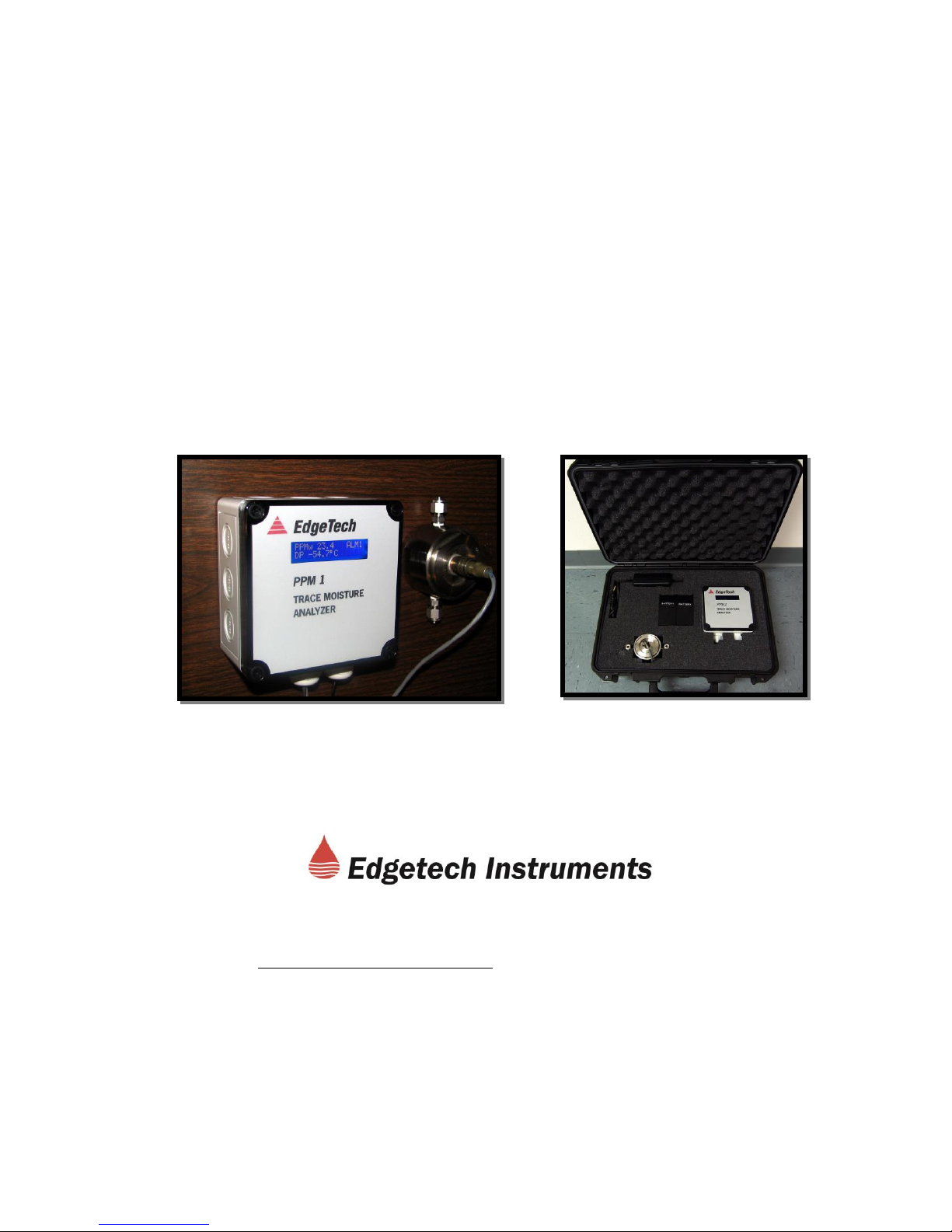
3.1 GENERAL DESCRIPTION
The PPM1 is a trace moisture analyzer designed specifically for monitoring low
levels of moisture, and reading them out in units of dew point and parts-permillion. This trace moisture analyzer utilizes an electro-chemical (P2O5) sensor in
combination with a proprietary semi-permeable diffusion membrane. The
principal of operation applies the Faraday’s Law of Electrolysis. It is a
fundamental measurement of the moisture present. The PPM1 is ideally used
in relatively clean, dry, inert gas applications. It is provided in a wall-mount
configuration. See Figure 3-2.
The PPM2 is a portable, battery operated version of the PPM1. It is provided in a
carrying case, with two gel-cell rechargeable batteries built in. See Figure 3-3.
3.2 TECHNICAL DESCRIPTION
3.2.1 THE PPM1/PPM2 SYSTEM
The gas passing through the phosphorous pentoxide cell results in a small
electrical current proportional to the quantity of water molecules (moisture) in the
sample. The small electrical current from the cell is conditioned so that it directly
corresponds to the concentration of moisture in the measured gas. This linear
output signal is available to actuate the programmable Alarm Relays, and also
provides information to the Digital Display and Analog Outputs. A
microprocessor controls all data processing and input and output functions of the
Instrument, ensuring a high accuracy measurement of moisture. Two separate
humidity parameters may be monitored and displayed.
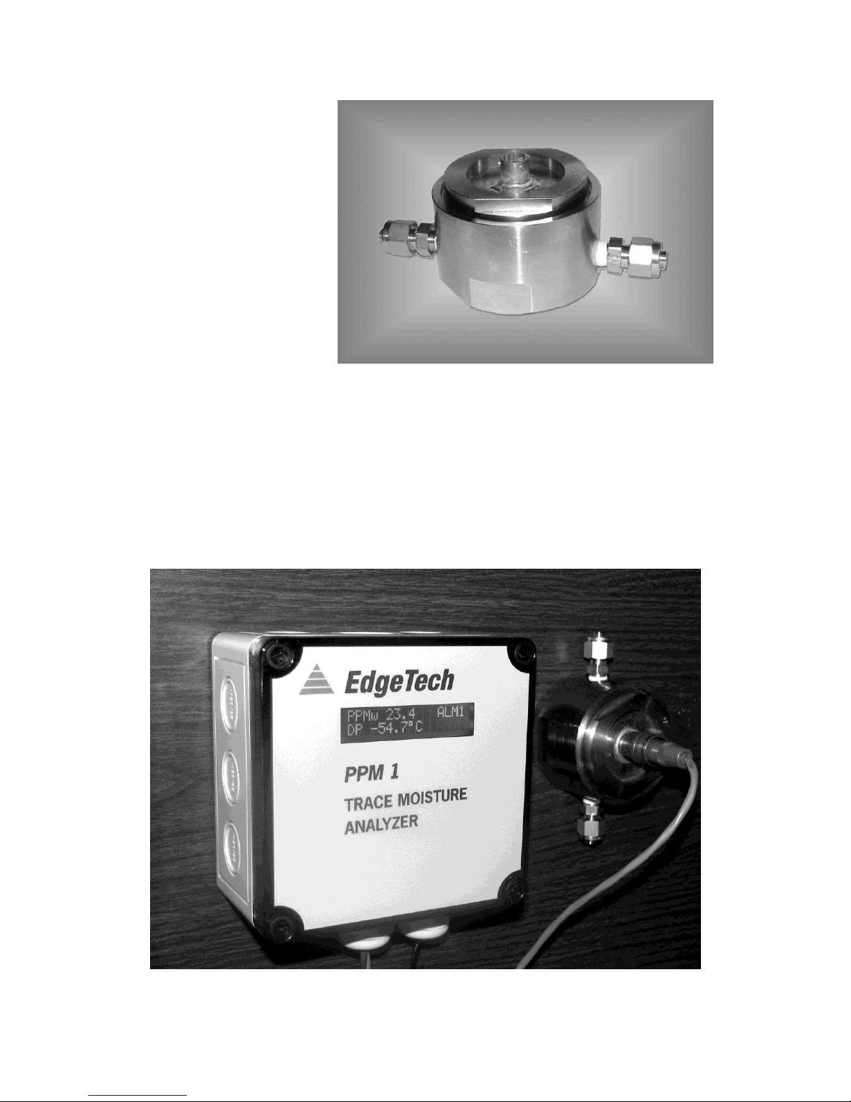
3.2.2 THE PHOSPHOROUS PENTOXIDE (P2O5) MOISTURE SENSOR
The Sensor utilizes an electrochemical (phosphorous pentoxide - P2O5 - coated)
sensor in combination with a proprietary semipermeable diffusion membrane.
This membrane allows the water vapor molecules to pass from the dry gas
stream into the sensor cavity at a rate that is a function of the partial pressure of
the water across the membrane. It also allows the hydrogen and oxygen
molecules, the byproducts of the electrolysis, to diffuse back into the gas stream.
The membrane “meters” the gas flowing into the sensor cavity, ELIMINATING
THE NEED FOR PRESSURE REGULATION AND CONSTANT FLOW, which
are required in most other electrolytic hygrometers.
The phosphorous pentoxide moisture sensor, also called an electrolytic cell, has
the ability to measure trace quantities of water vapor in a dry gas. Operation is
based on the fact that if a small dc voltage is applied, water vapor molecules can
be electrolyzed into their elements of hydrogen and oxygen. To electrolyze each
water molecule, it is known that two electrons are required. Therefore, the
6
Page 7
quantity of current used by
the cell is proportional to
the number of water
molecules being
electrolyzed. If the dc
excitation current is
measured, water vapor
content of the gas can be
displayed. This
measurement process
provides a fundamental
measurement of water
vapor. While in a typical
electrolytic cell the rate of
gas flow must be carefully Figure 3-1 The Phosphorous Pentoxide
controlled by the user for (P2O5) Moisture Sensor
accurate measurements,
this cell is independent of
gas flow rate. Although a fundamental measurement technique normally does
not require calibration, each cell is calibrated at the Factory before shipment to
the user to compensate for variations in the diffusion membranes. Figure 3-1
shows the moisture sensor.
Figure 3-2 The PPM1 with Wall Mount housing and Moisture Sensor
7
Page 8

Figure 3-3 The PPM2 Portable Trace Moisture Analyzer
Figure 3-2 shows the wall mounted PPM1, and Figure 3-3 shows the portable
battery-operated PPM2.
3.2.3 STANDARD FACTORY RANGES
As received from the Factory, the instrument is programmed for the following
standard conditions. These may be field modified by the user by using the RS232 serial port. See the Operation section for complete programming
information.
Digital Display Units: Set for ppmv and Dew Point
Analog Output Ranges: Set for 0 to 1250 ppmv, and -100°C to 0°C Dew Point
Alarm Relays Switching: Actuated at 100 ppmv, and -50°C Dew Point
RS-232 Port Update Rate: 5 seconds
8
Page 9

3.2.4 GASES TO AVOID
Caution: This instrument should not be used with gases that are corrosive or that
readily combine with phosphorous pentoxide to form water. GASES AND
MATERIALS THAT SHOULD BE AVOIDED INCLUDE CERTAIN ACIDS,
ALCOHOLS, CHLORINE, FLUORINE, HYDROGEN CHLORIDE, HYDROGEN
FLUORIDE, AMINES, AMMONIA, ALKYNES, ALKADIENES, AND ALKENES.
4.0 INSTALLATION
4.1 PLACEMENT OF INSTRUMENT
If possible, locate the PPM1 in a clean area. Choose a location where the
display may be conveniently observed. Depending on the location selected, it
may be convenient to wire the instrument prior to mounting.
4.2 MOUNTING
4.2.1 WALL MOUNTING THE DISPLAY
The plastic wall mount housing is mounted to a flat surface as follows:
1. Remove the front cover. Using a flat screwdriver, carefully unscrew the
four slotted plastic screws.
2. Mounting screws (not provided) are inserted in the same holes as the
cover screws. They must have a head diameter that is small enough
to fit inside the clearance holes, but large enough to press against the
collar located at the bottom of the holes. No. 8 pan head or round
head screws are recommended. See the wall mounting hole pattern in
the Appendix of this manual.
3. Reinstall the front cover. Do not over-tighten the cover mounting
screws.
4.2.2 SENSOR MOUNTING AND SAMPLING SYSTEM
The P2O5 Moisture Sensor is designed to measure very small quantities of Water
Vapor in the presence of other gases. It is manufactured of carefully selected
non-hygroscopic materials such as stainless steel. The use of more porous
materials such as plastic in your measuring system is strongly discouraged. In
order to obtain correct readings and acceptable response times, the sensor
sampling system must be carefully planned. Here are some recommendations:
Tubing should be clean stainless steel, not plastic.
If gas is brought from a long distance, use larger diameter tubing for faster
response time. Reduce diameter at the sensor fitting.
9
Page 10

Leak check the system after installation.
Purge the sampling system with dry gas after installation.
Do not expose the sensor to excess pressure.
Allow sufficient time for the system to dry out before attempting to take
measurements.
The sensor gas connections are ¼ inch (6.35 mm) compression fittings. See the
sensor mounting hole information in the Appendix of this manual.
If the gas to be measured is not completely clean, you may wish to install an
upstream filter in the system. A sintered stainless steel filter element is
recommended.
4.3 ELECTRICAL WIRING
See Figure 4-1, the electrical wiring diagram. All connections are clearly marked
on the circuit board.
4.3.1 SENSOR CONNECTIONS
The connector end of the Sensor cable is plugged into the Sensor. The other
(wired) end should be routed through the left hand feed-thru fitting at the bottom
of the electronics housing. Two wires are connected to the terminals marked
“SENSOR,” and the shield wire is connected to the terminal marked “CH GND”.
4.3.2 POWER CONNECTIONS
Power is supplied by a user-furnished unregulated DC power supply. Voltage
range may be between 18 and 30 VDC, at 100 mA maximum. Connect the
positive side to +VIN, and the negative side to RTN.
4.3.3 ANALOG OUTPUTS
The 4 to 20 mA Analog Outputs, if used, may be routed through the left-hand
feed-thru fitting. The positive side of Output 1 is connected to the terminal
marked OUT1, and the return to the adjacent terminal marked RTN. Similarly,
Output 2 is connected to OUT2 and RTN.
4.3.4 ALARM RELAYS
The Alarm Relays, if used, may be routed through the right-hand feed-thru fitting.
The contacts are Normally Open. Two alarm wires may be connected to the
terminals marked K1, and two may be connected to the terminals marked K2.
4.3.5 RS-232 SERIAL PORT
The built-in serial port is bi-directional, and includes a Type DB-9 RS-232
connector mounted on the circuit board. Any industry standard RS-232 cable
may be used. It is recommended that the installer wire the connector to one end
of the cable after routing it through one of the feed-thru fittings mounted to the
bottom of the electronics housing.
10
Page 11

Digital
Display
4 – 20 mA
Output 1
4 – 20 mA
Output 2
Sensor Cable
Connections
DC Power
Connections
Alarm
Relay K2
Alarm
Relay K1
RS-232
Type DB-9
Connector
Figure 4-1 PPS1/PPS2 Wiring Connections
11
Page 12

5.0 OPERATION
5.1 STARTUP
IT IS RECOMMENDED THAT A NEWLY INSTALLED INSTRUMENT BE DRIED
DOWN WITH DRY INERT GAS SUCH AS BOTTLED NITROGEN BEFORE
FINAL CONNECTION IS MADE BETWEEN THE SAMPLING SYSTEM AND
THE PROCESS GAS STREAM.
5.1.1 DRY DOWN PHASE 1
THE DRY GAS SHOULD FLOW THROUGH THE SAMPLING SYSTEM ONLY
(BYPASSING THE SENSOR) FOR THE FIRST FEW HOURS.
This procedure is recommended because during construction of the sampling
system, the components are exposed to the moisture in the ambient air, which
under normal conditions, can easily exceed 30,000 ppmv. These components
will be in equilibrium with the ambient air (having adsorbed moisture on their
surfaces). This water vapor will be desorbed from the walls of the tubing and
other surfaces of the sampling system components once the gas sample starts to
flow.
Unless steps are taken to remove any moisture in advance by following the
PHASE 1 dry down procedure, much of the moisture desorbed from the surfaces
of the sampling system will enter the electrochemical cell, most probably
exceeding the moisture concentration that the cell is designed to handle.
5.1.2 DRY DOWN PHASE 2
THE FLOW OF DRY GAS SHOULD THEN BE ROUTED THROUGH BOTH THE
CELL AND THE SAMPLING SYSTEM ASSEMBLY FOR AT LEAST ONE OR
TWO HOURS.
This procedure is recommended to dry down the measurement cell, and to
equilibrate the entire sampling system.
NOTE: ONCE THE ANALYZER HAS BEEN POWERED, THE POWER
SHOULD NOT BE SHUT OFF. FAILURE TO ADHERE TO THIS PROCEDURE
COULD SHORTEN THE USEFUL LIFE OF THE MEASUREMENT CELL.
The rationale behind this recommendation is that if power is always applied to
the measurement cell, any moisture that accidentally gets into the sampling
chamber will be eliminated by electrolyzing the water vapor molecules. This
keeps the moisture level on the phosphorous pentoxide low, lengthening its life.
12
Page 13

NOTE: IT IS GOOD PRACTICE TO INSTALL A SHUTOFF VALVE ON EACH
SIDE OF THE MEASUREMENT CELL, TO KEEP IT DRY WHEN OPENING
THE SAMPLING SYSTEM.
5.2 MEASURING DRY GASES
5.2.1 MEASUREMENT TIME
Measuring extremely dry gases is an art. Time and patience are involved. If you
are in a hurry, you may not obtain accurate results. As discussed above, all
materials are hygroscopic. That is, they have pores that retain water molecules.
When the level of moisture in a gas is decreased, for example, it may take a very
long time for all of the materials in the entire sampling system to outgas, or give
off all the excess water molecules that are trapped in the pores of every inside
surface of the system. Depending upon your unique conditions, it could take a
number of hours for complete stabilization of the moisture level in your gas. Be
sure you wait long enough before taking readings.
5.2.2 MATERIALS
As discussed in the Installation chapter of this manual, selection of materials is
extremely critical for proper dry gas sampling. For dry gas measurements, do
not use PVC or other porous tubing. Some plastic tubing such as Impolene™
may be used for gases in the higher ppm ranges. For measuring gases in the
lower ppm ranges, only stainless should be used.
If readings do not seem to stabilize after waiting a reasonable amount of time,
check to see if you have a leak from outside the system where the vapor
pressure is higher, or have excessively hygroscopic tubing, or possibly your
stainless tubing is contaminated and requires cleaning.
5.3 OPERATING THE INSTRUMENTS
5.3.1 THE PPM1
There are no controls to operate on the PPM1. The operator simply monitors the
digital display, or allows the analog and digital outputs to communicate with the
data acquisition system. When you first turn on the system, a short self-check
period occurs on the display, and then it quickly starts to show the two moisture
parameters that it is programmed to display. These are changeable in the field,
as shown in the following section on the Serial Port. The digital displays, as well
as the electrical outputs, are constantly updated.
5.3.2 THE PPM2
The PPM2 is a portable version of the PPM1. It is necessary to charge the builtin batteries before using it, and then to recharge them periodically. The charger
is supplied with the system.
13
Page 14

5.4 USING THE RS-232 SERIAL PORT TO PROGRAM YOUR
SETTINGS
5.4.1 SERIAL PORT SETUP
Plug a standard RS-232 cable into the DB-9 connector on the circuit board in the
PPM1 or PPM2. Plug the other end into your terminal or computer. If your
computer does not have a serial port, you will have to obtain a USB to Serial
adaptor, install the driver for it, and use the USB port.
Using a communications program such as Hyperterminal or equivalent, program
the settings as follows:
Baud Rate: 19.2K
Data Bits: 8
Parity: None
Stop Bit: 1
Flow Control: None
You should now see flowing data on your monitor,
displaying the same information that is shown on the
PPM1 or PPM2 Digital Display, with a periodic
update rate. If you do not, check your serial port
settings and cable connections.
NOTES:
1. WHEN PROGRAMMING ALPHABETIC CHARACTERS, USE UPPER
CASE ONLY.
2. IF YOU HAVE MORE THAN ONE WINDOW OPEN ON YOUR
DESKTOP, CLICK ON THE HYPERTERMINAL WINDOW TO SELECT
IT BEFORE PROGRAMMING.
5.4.2 CHANGING THE DIGITAL DISPLAY
You can select any two of several measured
or calculated parameters to appear on the
front panel Digital Display. Proceed as
follows:
Press the “Escape” key on your keyboard.
You will see three items that you can
program; D)isplay, C)al outputs, and R)s232,
as shown here. Since we are planning to
14
Page 15

select Display parameters, press “D” for Display. (We will C)alibrate the Outputs
and modify the R)s232 later.)
Note that initially, the displays are showing
units of ppmv (parts-per-million by volume)
and Dew Point in degrees C. First, we will
change ppmv to ppmw (parts-per-million by
weight).
You are given a choice whether to keep the
present units or to C)hange them. In this
case, we will select to C)hange them. Press
“C” on your keyboard. Select “Value 1” to change ppmv.
NOTE:
PRESSING THE SPACE BAR SCROLLS
THROUGH ALL THE AVAILABLE
SELECTIONS. PRESS “ENTER” TO
SELECT THE ONE YOU WANT TO KEEP.
Press the Space Bar several times to see
what units are available. When you see
ppmw, press “Enter”. You will then see the
window below. Press “Enter” again.
Than, you will be given a choice whether to
A)ccept or C)hange this modification. Press
“A” for A)ccept.
5.4.3 CHANGING THE
ANALOG OUTPUT RANGES
Continuing on, you will now be
given the opportunity to modify
the Analog Outputs. You do not
have to go back to the main
menu to do this, since it will
automatically be the next step.
15
Page 16

Again, use the Space Bar to
scroll through the available
options, and then use Enter to
select the one you want. If you
wish, you can also change the
measurement range that 4 to 20
mA corresponds to at this time.
Finally, press “A” to A)ccept the
change. You have completed
the process of modifying the
Analog Output.
In this example, let’s change the
4 to 20 mA Analog Output so that
it corresponds to Dew Point in °F
instead of Dew Point in °C.
Press “C” for C)hange. You will
than see this window. Press “2”
to Set Output 2, which
corresponds to Dew Point in °C.
We have selected DP°F, as
shown here. Next, press “X” for
eX)it.
16
Page 17

5.4.4 PROGRAMMING THE ALARM RELAYS
Next, you will be given the opportunity to modify the alarm settings if you wish.
Again you do not have to go back to the main menu, since the next step will
automatically put you in this mode.
The PPM1 and PPM2 have two alarms. They are Form A, (single-pole, singlethrow) normally open. You can make them correspond to any of the available
measured or calculated measurement parameters. You can independently
program the “ON” point and the “OFF” point for each relay. To enter the menu,
press “C” for C)hange.
You will then see the window shown below. In this example, we would like to
change Alarm 2. Note that it is now set for Dew Point in °C, and the relay
switches at 0.0 degrees. We are going to change it so that the alarm is now on
Dew Point in °F. We want the relay to open when the measurement is above
25°F, and we want it to close when the measurement is below 24°F. Therefore,
press “C” for C)hange.
You will now see the window shown here. Press “2” to select Alarm 2.
As before, you can use the Space Bar to select the desired unit and the Enter
key to lock it in. You can also choose to Enable or Disable any alarm. See the
following window.
17
Page 18

As you cycle through, you will be given the opportunity to replace DP°C with
DP°F, as shown here. At this time you can also change the measurement range
if you wish to. We will leave the default °F range of 50.0 to 0.0.
Next, we will program the alarm relay to open when the measurement is above
25 degrees, and close when the measurement is below 24 degrees.
NOTE: IT IS NOT GOOD PRACTICE TO SET THE “OPEN” POINT AND THE
“CLOSE” POINT TO THE SAME NUMBER. THIS MAY CAUSE EXCESSIVE
RELAY CHATTERING WHEN THE MEASUREMENT IS AT THAT QUANTITY.
18
Page 19

Next, we are asked if we want to Save the Changes, and we press “Y” for Y)es.
Now, we can select “X” for eX)it, and then “A” to A)ccept the changes.
19
Page 20

We have now made all the desired changes, and the display defaults to the
standard Hyperterminal window with periodic updates. See the illustration below.
5.4.5 CALIBRATING THE ANALOG OUTPUTS
If you have a precise
milliammeter, the PPM1 and
PPM2 allow you to check the
calibration of the two 4 to 20 mA
analog outputs. In order to utilize
this capability, connect the meter
in series with one of the analog
outputs and the load. Observe
the correct meter polarity.
Press the “Escape” key on your
keyboard, which will interrupt the
data stream and give you the
Calibration option. Than, press
“C” for C)alibrate. For this
example, select Output 1 to
calibrate. Next, read your
precision ammeter, which will give
you the high end current. It
should read around 20 mA. In
this case, the actual reading is
19.9 mA as shown. Type this
value in.
20
Page 21

Next, read the low end output current. It should be about 4 mA.
Type it in as shown above. The system then will
show you the predicted midpoint reading, which in
this case should be within the range of between
11.975 and 12.025 mA. This takes the cumulative
system errors in account.
As shown here the reading is exactly 12 mA,
and the system is within specifications.
Finally, press “X” for E)xit, and the
Hyperterminal window will return to the
default mode, showing continuous updates.
5.4.6 MODIFYING THE RS-232 PORT PARAMETERS
Two RS-232 Port parameters may be
changed in the field. You can enable the
Elapsed Time Stamp, and you can modify the
Update Rate. To start, proceed as follows:
From the
normal
updating
mode as
shown here, press “R” for Rs232. You can
then press “T” to select the Elapsed T)ime
Stamp, or press “R” to select the Update
R)ate. In this example we will leave the
Elapsed Time Stamp disabled, but we will change the Update Rate. See the
Windows shown below.
21
Page 22

First, press “R” to select the Update R)ate.
You have a choice of rates from 1 to 3600
seconds (1 second to 1 hour).
For this example we will insert an Update
Rate of 5 seconds, which is a convenient rate
to watch data updating on the computer
monitor.
See the
window on the right. Once that is done, you
only have to press “X” for eX)it, and you will
be back in the default updating mode as
shown below.
You have now completed all the
programming of the PPM1 or PPM2. You
can go back at any time and easily modify
any parameter in the field.
22
Page 23

6.0 MAINTENANCE
6.1 GENERAL
Very little maintenance is required for long term operation of the PPM1 and
PPM2 Trace Moisture Analyzers. They have been designed for continuous
operation over very long periods of time. The electronics unit needs no
maintenance. The trace moisture sensor may gradually get contaminated, and
may have to be returned to the Factory for cleaning after very long periods of
operation.
6.1.1 FILTERS
It is considered good practice to have an upstream particle filter in the line. It will
keep the moisture sensor clean and will keep dust and other contaminants out of
the cavity. The filter should be non-hygroscopic, and preferably should be made
of sintered stainless steel. A maintenance schedule should be set up to clean or
replace the element periodically. A clogged filter will retain moisture and slow
down the system.
6.1.2 BATTERY MAINTENANCE
The PPM2 Portable Analyzer contains a pair of gel call batteries. These must be
periodically recharged. A plug-in charger is included with the system. After a
few discharge cycles to determine available operating time, you should be able to
initiate a preventative maintenance program for periodic recharging that will keep
the unit ready for use. If desired, the battery charger may be plugged into the
PPM2 continuously without harm.
6.2 GASES
Certain gases must never be used with this system. See GASES TO AVOID in
the Introduction section of this manual. The use of these gases may damage or
contaminate the moisture sensor.
23
Page 24

7.0 SPECIFICATIONS
Technology Used: P2O
Measured Parameter: PPMv (Parts-per-Million by Volume)
Calculated Parameters: Dew Point, PPMw (Parts-per-Million by
Weight), Others
Accuracy: ± 5% of PPMv reading, typical
Measurement Range: PPMv: 1250 to 0.1 ppm
Dew Point: -20°C to -95°C
Pressure: 0 to 200 psig
Response Time: 90% of step change in one minute, typical
Hysteresis: None
Temperature: Ambient: 0 to 50°C
Sample Gas: 0 to 50°C
Electrical Outputs: Analog Outputs (2): 4 to 20 mA
(Field Programmable) Load: 0 to 400Ω
Digital Interface: RS-232C, bi-directional
Alarm Relays (2): Form A (Normally Open)
Contact Rating: 3A at 250VAC/30VDC
Digital Display: LCD, 2 line, backlit
Sensor Gas Connections: ¼ inch (6.35 mm) compression fittings
Model PPM1:
Power Requirements: 18 to 30 VDC unregulated, 100 mA maximum
Standard Cable: 6 feet (1.8 meter)
Dimensions: Enclosure (LWD): 5.1 in (13cm) X 5.1 in
(13cm) X 3 in (7.6cm)
Phosphorous Pentoxide Cell
5,
DB-9 Connector
24
Page 25

Weight: Entire System: 4 lbs (1.8kg)
MODEL
APPLICATION
DESCRIPTION
PPM2 – FV
Positive Pressure
A portable battery
powered trace moisture
analyzer with built-in
Flow Valve
PPM2 - VP
Atmospheric Pressure
or Vacuum
A portable battery
powered trace moisture
analyzer with built-in
Vacuum Pump
Available PPM1
Options/Accessories: Right angle mounting bracket (-MB)
Additional sensor cable length (-SCBL)
Note: Specify length to 500 ft. max.
Model PPM2:
Power Requirements: Battery Powered, 2 gel cells (12 VDC) in series
Battery Charger included
(115/230Vac to 24Vdc)
Nominal Operating Time: 8 to 10 hours
Standard Cable: 6 feet (1.8 meter)
Dimensions: Carry Case (LWD): 19 in (48cm) X 14 in
(36cm) X 7 in 18cm)
Weight: Entire System: 15 lbs. (6.8kg)
Available PPM2 Optional Configurations:
25
Page 26

8.0 APPENDIX
8.1 PPM1 MOUNTING DIMENSIONS
26
Page 27

8.2 SENSOR DIMENSIONS
27
Page 28

8.3 EDGETECH INSTRUMENT’S WARRANTY
All equipment manufactured by Edgetech Instruments Inc. is warranted
against defective components and workmanship, and will be repaired at
their plant in Massachusetts, free of charge, for a period of twelve
months. Malfunction due to improper use is not covered in this warranty
and Edgetech Instruments disclaims any liability for consequential
damage resulting from defects in the performance of the equipment. No
product is warranted as being fit for a particular purpose and there is no
warranty of merchantability. This warranty applies only if (i) the items are
used solely under the operating conditions and in the manner
recommended in the instruction manual, specifications, or other
literature; (ii) the items have not been misused or abused in any manner
or repairs attempted thereon; (iii) written notice of the failure within the
warranty period is forwarded to Edgetech Instruments and the directions
received for properly identifying items returned under warranty are
followed; and (iv) the return notice authorizes Edgetech Instruments to
examine and disassemble returned products to the extent Edgetech
Instruments deems necessary to ascertain the cause for failure. The
warranties expressed here are exclusive. There are no other warranties,
either expressed or implied, beyond those set forth here, and Edgetech
Instruments does not assume any other obligation or liability in
connection with the sale or use of these products.
Equipment not manufactured by Edgetech Instruments is supported only
to the extent of the original manufacturer’s warranties.
28
Page 29

Notes
29
 Loading...