

Page 1
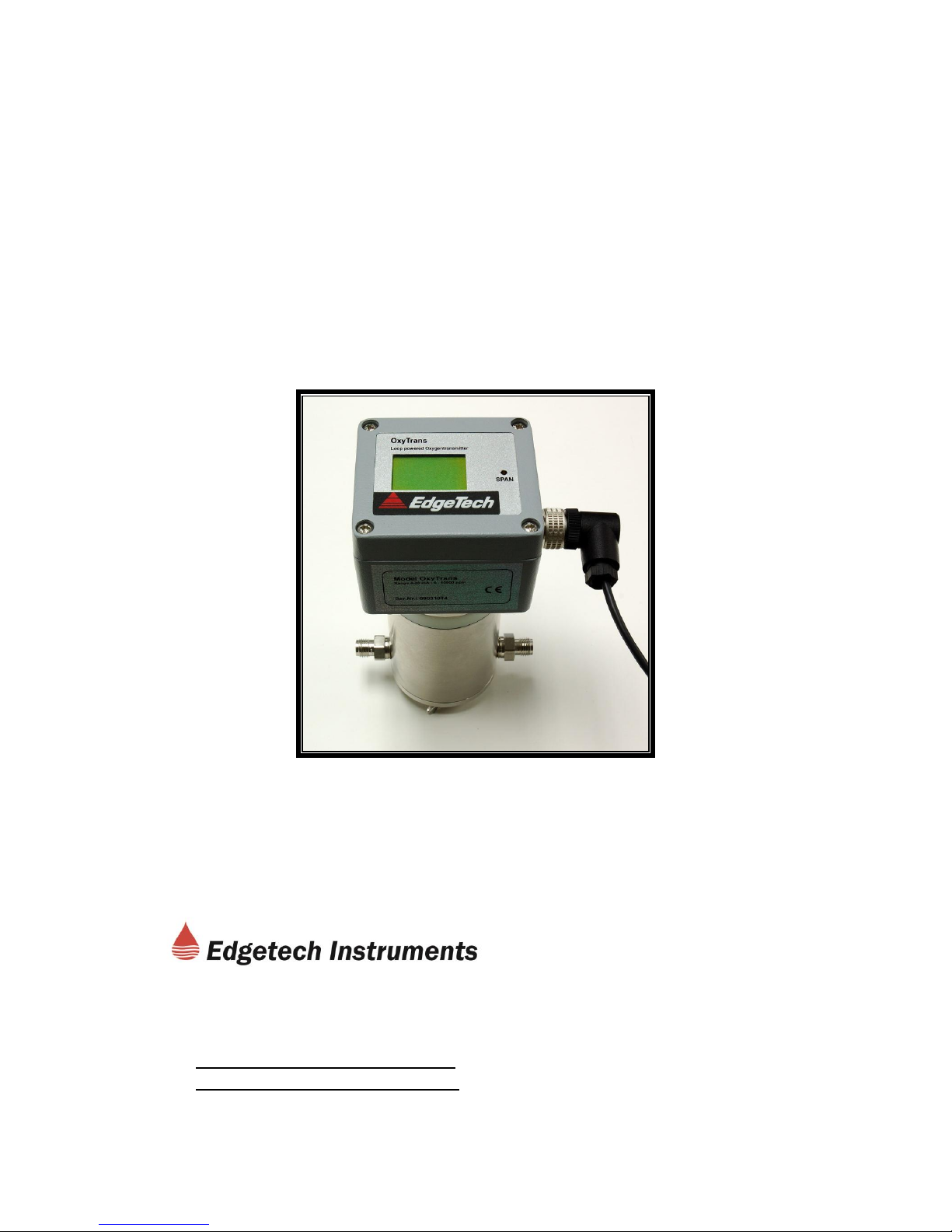
OxyTrans
Loop Powered Two Wire
Oxygen Transmitter
OPERATORS MANUAL
19 Brigham Street Unit 8
Marlborough, MA 01752
508-263-5900 Fax: 508-486-9348
www.edgetechinstruments.com
h2o@edgetechinstruments.com
Rev. A April 2009
Page 2

OxyTrans
QUICK STARTUP GUIDE
STARTUP
1. Using the supplied Mounting Kit, mount the OxyTrans in
position to measure the desired gas.
Caution: The cell must be mounted vertically with Digital
Display at the top.
2. Connect input and output tubing. See Manual for proper tubing
materials. Shutoff valves should be installed on both sides of
the sensor.
3. Connect loop power supply, using cable supplied.
4. Connect data acquisition system or other series load if
required.
5. Allow sufficient equilibration time before recording data.
Page 3

TABLE OF CONTENTS Page
1.0 Quick Startup Guide
2.0 Commitment to Quality 3
3.0 Introduction 4
3.1 General Description 4
3.2 Micro Fuel Sensor 4
3.3 The Effect of Pressure 4
3.4 Calibration Characteristics 5
3.5 Standard Configurations 5
3.6 Options and Accessories 6
4.0 Installation 8
4.1 Mounting 8
4.2 Plumbing 8
4.3 Electrical Connections 9
5.0 Operation 11
5.1 Digital Display 11
5.2 Analog Output 11
6.0 Maintenance
6.1 Calibration 12
6.2 Out of Service Procedure 13
6.3 Troubleshooting 13
6.4 Cell Replacement 14
7.0 Specifications 18
8.0 Appendix 19
8.1 Warranty 20
8.2 Oxygen Cell Housing Drawing 21
8.3 Intrinsically Safe Barrier (Optional) 22
1
Page 4

LIST OF ILLUSTRATIONS Page
3-1 Cell I/O Curve 5
3-2 Standard Configurations 6
4-1 Mounting Kit 8
4-2 Mounting the Transmitter 9
4-3 Electrical Connections 10
5-1 Digital Display 11
6-1 Calibration Adjustment 12
LIST OF TABLES Page
3-1 Standard Factory Ranges 6
2
Page 5

2.0 EDGETECH INSTRUMENTS INC.'S COMMITMENT
TO QUALITY
To Our Customers:
Thank you for purchasing one of our products. At Edgetech
Instruments Inc., it is our policy to provide cost-effective products and
support services that meet or exceed you requirements, to deliver
them on time, and to continuously look for ways to improve both. We
all take great pride in the products we manufacture.
We want you to be entirely satisfied with your instrument. The
information contained in this manual will get you started. It tells you
what you need to get your equipment up and running, and introduces
its many features.
We always enjoy hearing from the people who use our products. Your
experience with our products is an invaluable source of information
that we can use to continuously improve what we manufacture. We
encourage you to contact or visit us to discuss any issues whatsoever
that relate to our products or your application.
The Employees of Edgetech Instruments Inc.
3
Page 6

3.0 INTRODUCTION
3.1 GENERAL DESCRIPTION
The Edgetech Instruments Inc. OxyTrans 2-wire 4 to 20 mA Loop Powered
Oxygen Transmitter consists of two sub-systems:
1. The Analyzer Unit, which is an electro-chemical fuel sensor designed
for measuring oxygen.
2. The Electronics Unit, which provides sensor signal conditioning, digital
display, and electrical analog outputs.
The gas to be measured is transported to the sensor membrane of the Micro
Fuel sensor. This sensor is an electro-chemical and galvanic cell that transforms
the oxygen in the measured gas into an electrical current.
The Electronics Unit measures this electrical signal, providing visual and
electrical information to the operator, directly in either parts-per-million of oxygen
(ppm O2), or as a percentage of the total measured gas (%O2).
3.2 MICRO FUEL SENSOR
The oxygen sensor is a sealed plastic disposable electrochemical sensor. The
active components are a cathode and an anode, which are immersed in a 15%
aqueous KOH electrolyte solution. When oxygen in the sample gas is sensed by
the membrane, the cell converts the resulting chemical reaction into an electrical
current change. Its action is similar to that of a battery, with one important
difference. In a battery, all reactants are stored within the cell. In the oxygen
sensor, one of the reactants, oxygen, comes from outside the device as a
constituent of the sample gas being analyzed.
3.3 THE EFFECT OF PRESSURE
In order to determine the amount of oxygen present in the gas sample, it is
necessary that the gas diffuse into the cell under constant pressure, by Dalton’s
Law. If the total pressure increases during a measurement, the rate that oxygen
reaches the cathode through the diffusing membrane will also increase. The
electron transfer, and therefore the resulting measured output current, will
increase even though the oxygen concentration in the sample has not changed.
Therefore, it is important that the sample pressure at the fuel cell remain
constant during measurements.
4
Page 7

0
10
20
30
40
50
60
70
80
90
100
0 0,2 0,4 0,6 0,8 1
oxygen concentration %
output zell in µA
3.4 CALIBRATION CHARACTERISTICS
Since the total pressure of the sample gas at the input of the measuring cell
is constant, a convenient characteristic of the cell is that the current produced in
an external circuit is directly proportional to the rate at which oxygen molecules
reach the cathode, and this rate is directly proportional to the concentration of
oxygen in the gaseous mixture. In other words it has a linear characteristic
curve, as shown in Figure 3-1. An advantage is that measuring circuits do not
have to compensate for nonlinearities.
In addition, since there is zero output in the absence of oxygen, the
characteristic curve has close to an absolute zero (within ± 1 ppm oxygen).
In practical application, zeroing is still used to compensate for the
combined zero offsets of the cell and the electronics. The electronics is
zeroed automatically when the instrument power is turned on.
Figure 3-1 Characteristic Input/Output Curve for the Oxygen Cell
3.5 STANDARD FACTORY CONFIGURATIONS
The Edgetech Instruments Inc. OxyTrans series of transmitters are available in a
number of
convenient configurations. These include both vertical and horizontal mounts, so
that the digital display may be viewed either from the top or from the front.
Intrinsically Safe barriers are also available if required.
5
Page 8
A number of standard ranges are available. These include:
RANGE
PARTS-PER-MILLION
PERCENT OXYGEN
0 to 10
X
0 to 100
X
0 to 1000
X
0 to 10,000
X
0 to 1
X
0 to 25
X
Table 3-1 Standard Factory Ranges
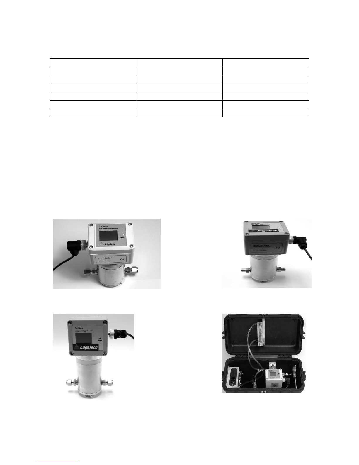
3.6 OPTIONS AND ACCESSORIES
Other standard configurations include a Panel Mount unit with optional safety
barriers. A Portable unit is available in a carrying case with a built-in sampling
system, including a flow meter, flow adjustment valve, sintered filter, vacuum
pump, and power supply. Also available is an Explosion-Proof (ATEX approved)
version. A unit with electrical interface compatible with the Hart Protocol is a
standard option. Additional ranges are available on special order. Some ranges
provided in the past include 0 to 20,000 ppm, 0 to 50,000 ppm, and 0 to 100%
O2. See Figure 3-2 below.
Figure 3-2a Explosion-Proof Unit Figure 3-2b Vertical Mount
Figure 3-2c Horizontal Mount Figure 3-2d Portable Unit
6
Page 9

Figure 3-2e Panel Mount Unit
7
Page 10

4.0 INSTALLATION
The installation of the transmitter is very simple. However, it must be done with
care to ensure successful operation and data collection. Select a mounting
location that will allow convenient viewing of the built-in Digital Display.
Note: The cylindrical portion of the cell must be mounted vertically for
proper operation, with the display at the top. Both horizontal and vertical
digital displays are available. The correct one should be carefully selected.
4.1 MOUNTING
A Mounting Kit, shown in
Figure 4-1, is provided for
easy installation. It
includes the mounting
hardware, and also an
interconnecting cable and
extra compression fitting
nuts.
First, screw the supplied
Mounting Plate securely to
a wall or other vertical
surface, using two No. 10
screws. Hole centers are
1-1/16 inch (27mm) apart.
Then, run the large
stainless steel pipe clamp Figure 4-1 Mounting Kit
through the slots in the sides
of the Mounting Plate. Insert the OxyTrans transmitter as shown in Figure 4-2.
Tighten the screw, locking the cell housing in place. Do not over-tighten.
4.2 PLUMBING
For low percentages of oxygen in the sample gas, proper selection and
installation of tubing is critical for successful measurements.
Recommendations for trace O2 measurements:
1. Use only stainless steel tubing.
2. If there is a possibility that the tubing is contaminated, it should be cleaned
before installation.
3. The entire plumbing system should be leak-checked after installation.
8
Page 11

4. After the plumbing installation has been completed, the system may have
PIPE CLAMP
MOUNTING
PLATE
to be operated overnight to purge it.
Figure 4-2 Mounting the Transmitter
A good stainless steel sintered filter or a borosilicate glass filter can increase the
length of maintenance-free operation if the gas contains dust particles or other
impurities.
Install shut-off valves on both sides of the sensor so that it may be isolated from
the system when not being used. This ensures a longer cell life.
For higher Oxygen concentrations, some plastic materials such as Tygon™ are
acceptable. Do not use soft PVC tubing.
Adjust the flow rate between 1-2 SCFH (0.5 to 1 L/min).
4.3 ELECTRICAL CONNECTIONS
The system provides a loop-powered 4 to 20 mA output signal, corresponding to
the oxygen measurement range specified. “Loop powered” means that the
OxyTrans is powered by the current loop itself. The OxyTrans, power supply,
and the (optional) signal-conditioning device used to measure the 4 to 20 mA
signal are all connected in a series loop, so that the same current flows through
all. The loop power supply voltage should be between 10 and 36 VDC. See
Figure 4-3 below for OxyTrans connections.
9
Page 12

Pin 4: + RED
Pin 3: – BLUE
Output: 4 – 20 mA
Load: 0 to 500 Ohms
PIN 3 (-)
PIN 4 (+)
Figure 4-3 Electrical Connections
The electrical interface cable supplied is approximately 57 inches (22 cm) long.
It is color coded for easy installation. The positive side (Pin 4) is red, and the
return side (Pin 3) is blue. The pin numbers are marked on the connector on the
body of the OxyTran, in case you wish to fabricate your own cables.
After applying power to the loop, you will see a value on the display. Allow
sufficient time for the entire system to equilibrate before attempting to record
valid data. Equilibration time is longer for low concentrations of oxygen than it is
for higher concentrations.
10
Page 13

5.0 OPERATION
Operation of the OxyTrans is very simple. Open the shut-off valves on the
upstream and downstream sides of the sensor. For most models, there are no
switches or other controls. The operator simply has to be sure that the gas flow
rate is within the specified range (1 to 2 SCFH, or 0.5 to 1 L/min.), and that new
readings have completely equilibrated before data is taken.
5.1 DIGITAL DISPLAY
The Digital Display shows you the current oxygen value. A bar graph at the top
symbolizes the analog output signal. See Figure 5-1.
Figure 5-1 Digital Display
5.2 ANALOG OUTPUT
The 4 to 20 mA electrical output will follow the changes in value of the measured
Oxygen, just as the digital display does. It may be remotely measured with a
series DC milliammeter, or used to drive a process controller or data acquisition
system.
11
Page 14

MAINTENANCE
6.1 CALIBRATION
Although the OxyTrans comes Factory-calibrated, you may wish to recalibrate
the unit at some time. Calibration of the OxyTrans is very simple. A calibration
gas with a known Oxygen value is required.
CALIBRATION ADJUSTMENT SCREW
Figure 3
Figure 6-1 Calibration Adjustment
Notes:
1. Select a calibration gas that is equivalent to your measurement range.
For example, if you have the 0 to 100 ppm unit, select a gas with an
Oxygen value of approximately 40 – 50 ppm O2 in N2.
2. Be sure that line pressure remains constant during the calibration.
3. If you have the 0 to 25% Oxygen range, air may be used for the
calibrating gas. Air consists of approximately 21% Oxygen.
4. Be sure to wait until complete equilibration before calibrating the unit.
If the Oxygen concentration is very low, or if the sampling system is
large, waiting a long time may be required.
12
Page 15

To calibrate the OxyTrans:
1. Locate the Calibration adjustment screw. See Figure 6-1.
2. Connect the calibration gas to the compression fitting. For low ranges, do
not leave the downstream fitting open to room air. We recommend that you
use a few feet of tubing on the downstream side, to keep room air from entering
the cell.
3. After complete equilibration (see Note 4 above), the Digital Display will show
the current Oxygen value.
4. Once the value is stable, adjust the Calibration screw with a small
screwdriver until the Digital Display shows the correct value.
6.2 WHAT TO DO WHEN OUT OF SERVICE
If the OxyTran is not going to be used for a period of 12 hours or more, Step 1
below should be followed. To put it back into operation, see Steps 2 and 3
below:
1. Make sure that the shut-off valves on the upstream and downstream sides
of the measurement cell are closed, isolating the cell. No oxygen from the
outside air or from the gas pipeline should be in contact with the
measurement cell. This will increase the cell life.
2. After restarting the equipment, purge the sampling system with dry
nitrogen before using it for O2 measurements.
3. If the system has not been used for a long time, recalibrate against an
Oxygen standard gas.
6.3 TROUBLESHOOTING
If the OxyTrans displays incorrect or erratic readings of the Oxygen concentration
in the measured gas:
Possible Causes May Be:
1. Inaccurate calibration.
2. Leakage in the sampling system.
3. Atmospheric Oxygen may be diffusing in through the downstream port.
4. Unstable system pressure.
5. Defective Oxygen Cell.
13
Page 16

Possible Solutions May Be:
1. Turn the analyzer off, and then back on again. Now proceed to
carefully calibrate the analyzer.
2. Check the complete sampling system for leaks, and be sure that
everything is tight.
3. Increase the flow rate and/or add downstream tubing in order to dilute
or minimize the introduction of oxygen from the room back into the
sensor.
4. Be sure that the measurement gas pressure is stable. Changes in the
operating pressure will cause measurement value variations. The cell
is designed to measure Oxygen at atmospheric pressure. There
should be nothing downstream that could restrict gas flow and increase
cell pressure.
Caution: The measurement cell could be destroyed if the
maximum pressure rating is exceeded.
If necessary, use a non-adjustable pressure reducer on the
measurement gas inlet.
5. If none of these steps correct the problem, than replace the sensor.
6.4 CELL REPLACEMENT
The sensor used in this analyzer uses electrolytes which contain toxic
substances, mainly lead and potassium hydroxide. These can be harmful
if touched, swallowed, or inhaled. Avoid contact with any fluid or powder
in or around the unit. What may appear to be plain water could contain
one of these toxic substances. In case of eye contact, immediately flush
eyes with water for at least 15 minutes. Call physician. (A Material Safety
Data Sheet is available from the Factory.)
CAUTION: Do not disturb the integrity of the cell package until the
cell is to actually be used. If the cell package is punctured and air is
permitted to enter, the cell may require an excessively long time to
reach zero after installation, possibly as long as one to two weeks!
6.4.1 WHEN TO REPLACE A CELL
The ageing characteristic of the Oxygen measurement cell shows an almost
constant output throughout its useful life. Near the end of its life it falls off
sharply, reaching zero output at the end.
14
Page 17

Before replacing the cell:
a. Check your calibration gas to make sure it is within specifications.
b. Check for leaks both upstream and downstream of the cell, where oxygen
may be leaking into the system.
c. Are you trying to measure trace quantities of Oxygen with a large sampling
system that has a large amount of surface area? The response time of the
system in this case may be very slow.
d. Has the power supply and the entire electrical system been checked?
If there are no leaks and the calibration gas is known to good, but you still get no
response, replace the cell.
6.4.2 STORING AND HANDLING OF REPLACEMENT CELLS
To have a replacement cell available when it is needed, we recommend that one
spare cell be purchased 9-10 months after installing the OxyTrans, or shortly
before the end of the cell's one year warranty period.
Note: Do not stockpile cells. The warranty period starts on the day of
shipment.
The spare cell should be carefully stored at room temperature, in an area that is
not subject to large variations in ambient temperature, and not subject to rough
handling.
6.4.3 REMOVING THE MEASUREMENT CELL
The Oxygen cell is built into the cell housing. To take out a defective or unusable
cell, proceed as follows:
1. Shut off the unit.
2. Unscrew the wing nut from the cell block.
3. Carefully remove the bottom of the cell block that contains the cell.
4. Take the cell carefully from the bottom. Do not touch the sensor
surface.
5. Correctly dispose of old cells according to proper disposal regulations.
A Material Safety Data Sheet (MSDS) is available from the Factory.
15
Page 18

6.4.4 INSERTION OF A NEW MEASUREMENT CELL
Caution: Do NOT touch the sensor membrane. The surface has a small
Teflon® membrane which can be destroyed by contact. The sensor will
have to be replaced if the membrane surface is destroyed.
For installation of the new cell, proceed as follows:
1. Shut off the unit.
2. Take the new cell out of the package.
3. Unscrew the wing nut from the cell block. Be careful that you don’t shift
or destroy the O-Ring.
4. Carefully place the cell at the center of the cell block bottom. The
sensor membrane wall will be below.
5. Press the cell together with the cell bottom in the cell block. The
contact surface will be on the top. Screw the wing nut back on securely.
Note: The cover will fit correctly only in one direction.
6. Restart the equipment and purge the sampling system with dry
nitrogen immediately.
6.4.5 CELL WARRANTY
Warranty period begins on the date of shipment. The customer should purchase
only one spare cell. Do not attempt to stockpile spare cells.
Note: These cells are not designed for applications where CO2 is a
major component in the sample.
However, concentrations of 1,000 ppm or less of CO2 will not adversely affect the
cell performance. Consult us for available options for either intermittent or
continuous CO2 exposure.
If a cell was working satisfactorily, but ceases to function before the warranty
period expires, the customer will receive credit toward the purchase of a new cell.
If you have a warranty claim, you must return the cell in question to the factory
for evaluation. If it is determined that failure is due to faulty workmanship or
material, the cell will be replaced at no cost to you.
16
Page 19

Note: If there is evidence of damage due to tampering or
mishandling, the cell warranty will be null and void.
6.4.6 CLEANING THE MEASUREMENT CELL HOUSING
If you have a reason to clean the cell housing, this may be done very carefully
with a lint-free clean cloth. Be cautious not to damage or break the gold colored
spring contacts inside.
Note: If there is heavy contamination inside the cell housing, send
the unit to the Factory for cleaning. The electronics will have to
be removed and then remounted.
17
Page 20

7.0 SPECIFICATIONS
Measurement Range: 0-10; 0-100; 0-1000; 0-10000 ppm O2
0-1; 0-25 % O2
Calibration Accuracy: With calibration gas (example: 80 ppm O2 in N2)
+/- 2% FS at constant temperature
+/- 5% FS over full temperature range
(at 0 -10ppm +/- 1ppm)
Resolution: 0.1 ppm
Response time: To 90 % of FS at 25°C
0-10 ppm < 45 s
0-100 ppm < 30 s
0-1000 ppm < 10 s
Operating Temperature: 0 - 50°C
Sample Pressure: 0.1 - 1 bar
Output signal: 4 -20 mADC isolated
Display: LCD Digital Dispay
Loop Power Supply: 10 - 36 VDC
Oxygen sensor: Chemical Cell
Expected Sensor Life: >2 years
Size: (H x W x D) 6.3 x 4.7 x 2.6 inches (160 x 120 x 65mm)
Weight: 3lbs (1.4 kg)
18
Page 21

8.0 APPENDIX
8.1 Warranty Statement
8.2 Oxygen Cell Housing Drawing
8.3 Intrinsically Safe Barrier for Panel Mount (Optional)
19
Page 22

8.1 WARRANTY STATEMENT
All equipment manufactured by Edgetech Instruments Inc. is warranted
against defective components and workmanship for repair at their plant
in Massachusetts, free of charge, for a period of twelve months.
Malfunction due to improper use is not covered in this warranty and
Edgetech Instruments Inc. disclaims any liability for consequential
damage resulting from defects in the performance of the equipment. No
product is warranted as being fit for a particular purpose and there is no
warranty of merchantability. This warranty applies only if (i) the items are
used solely under the operating conditions and in the manner
recommended in the instruction manual, specifications, or other
literature; (ii) the items have not been misused or abused in any manner
or repairs attempted thereon; (iii) written notice of the failure within the
warranty period is forwarded to Edgetech Instruments Inc. and the
directions received for properly identifying items returned under warranty
are followed; and (iv) the return notice authorizes Edgetech Instruments
Inc. to examine and disassemble returned products to the extent
Edgetech Instruments Inc. deems necessary to ascertain the cause for
failure. The warranties expressed herein are exclusive. There are no
other warranties, either expressed or implied, beyond those set forth
herein, and Edgetech Instruments Inc. does not assume any other
obligation or liability in connection with the sale or use of said products.
Equipment not manufactured by Edgetech Instruments Inc. is supported
only to the extent of the original manufacturer’s warranties
20
Page 23

8.2 OXYGEN CELL HOUSING DRAWING
21
Page 24

8.3 INTRINSICALLY SAFE BARRIER FOR PANEL MOUNT
(OPTIONAL)
22
Page 25

NOTES
23
 Loading...