

Page 1

EdgeTech
8242XS RELEASE
USER HARDWARE MANUAL
0004815_Rev_G 3/30/2018
4 Little Brook Road
West Wareham, MA 02576
Tel: (508) 291-0057
Fax: (508) 291-2491
www.EdgeTech.com
Page 2

ii
The information, figures, and specifications in this manual are proprietary and are issued in strict
confidence on condition that they not be copied, reprinted, or disclosed to a third party, either wholly or
in part, without the prior, written consent of EdgeTech. Any reproduction of EdgeTech supplied software
or file sharing is strictly prohibited.
Copyright © 2011 – 2018 EdgeTech. All rights reserved.
8242XS Release 0004815_REV_G
Page 3

iii
ATTENTION – READ THIS FIRST!
All personnel involved with the installation, operation, or maintenance of the equipment described in this
manual should read and understand the warnings and cautions provided below.
CAUTION!
This equipment contains devices that are extremely sensitive to static
electricity. Therefore, extreme care should be taken when handling them.
Normal handling precautions involve the use of anti-static protection
materials and grounding straps for personnel.
WARNING!
High Voltage may be present in all parts of the system. Therefore, use
caution when the electronics are removed from their containers for
servicing.
Warnings, Cautions, and Notes
Where applicable, warnings, cautions, and notes are provided in this manual as follows:
WARNING!
Identifies a potential hazard that could cause injury or death.
CAUTION!
Identifies a potential hazard that could damage equipment or data.
NOTE: Recommendations or general information that is particular to the
material being presented.
Page 4

iv
HARDWARE VARIATIONS AND COMPATIBILITY
The 8242XS Release contains both standard and proprietary hardware. At times, EdgeTech may change
the standard components due to their availability or performance improvements. Although the
component manufacturers—along with their models and styles—may change from unit to unit,
replacement parts will generally be interchangeable.
EdgeTech will make every effort to see that replacement components are interchangeable and use the
same software drivers (if applicable). At times, however, direct replacements may not exist. When this
happens, EdgeTech will provide the necessary drivers with the replacement part, if applicable.
EdgeTech may also change certain hardware per customer requirements. Therefore, portions of this
manual, such as parts lists and test features, are subject to change. These sections should be used for
reference only. When changes are made that affect system operation, they will be explicitly noted. Also,
some options and features may not be active in the customer’s unit at time of delivery. Upgrades will be
made available when these features are implemented.
Contact E
DGETECH CUSTOMER SERVICE with any questions relating to compatibility.
8242XS Release 0004815_REV_G
Page 5

v
REVISION
DESCRIPTION
DATE
APPROVAL
A
Release to Production
01/02/2011
RM B Updates
N/A
RM C Updates
N/A
RM D Corrected to Historical Rev
10/05/2012
RM
E
Change Release Load Spec
10/05/2012
RM
F
Update Format & Pictures
11/10/2014
RM G Updates to Content, Drawings,
03/30/18
RM
ABOUT THIS DOCUMENT
We, the employees at EdgeTech, would like to thank you for purchasing the 8242XS Release. At EdgeTech,
it is our policy to provide high-quality, cost-effective products and support services that meet or exceed
your requirements. We also strive to deliver them on-time, and to continuously look for ways to improve
them. We take pride in the products we manufacture, and want you to be entirely satisfied with your
equipment.
Purpose of this Manual
The purpose of this manual is to provide the user with information on the setup and use of EdgeTech’s
8242XS Release. Although this manual encompasses the latest operational features of the 8242XS, some
features may be periodically upgraded. Therefore, the information in this manual is subject to change and
should be used for reference only.
Liability
EdgeTech has made every effort to document the 8242XS Release in this manual accurately and
completely. However, EdgeTech assumes no liability for errors or for any damages that result from the
use of this manual or the equipment it documents. EdgeTech reserves the right to upgrade features of
this equipment, and to make changes to this manual, without notice at any time.
Revision History
Page 6

vi
WARRANTY STATEMENT
All equipment manufactured by EdgeTech is warranted against defective components and workmanship
for a period of one year after shipment. Warranty repair will be done by EdgeTech free of charge.
Shipping costs are to be borne by the customer. Malfunction due to improper use is not covered in the
warranty, and EdgeTech disclaims any liability for consequential damage resulting from defects in the
performance of the equipment. No product is warranted as being fit for a particular purpose, and there is
no warranty of merchantability. This warranty applies only if:
i. The items are used solely under the operating conditions and in the manner recommended in
Seller's instruction manual, specifications, or other literature.
ii. The items have not been misused or abused in any manner, nor have repairs been attempted
thereon without the approval of EdgeTech Customer Service.
iii. Written notice of the failure within the warranty period is forwarded to Seller and the directions
received for properly identifying items returned under warranty are followed.
iv. The return notice authorizes Seller to examine and disassemble returned products to the extent
Seller deems necessary to ascertain the cause for failure.
The warranties expressed herein are exclusive. There are no other warranties, either expressed or implied,
beyond those set forth herein, and Seller does not assume any other obligation or liability in connection
with the sale or use of said products. Any product or service repaired under this warranty shall be
warranted for the remaining portion of the original warranty period only.
Equipment not manufactured by EdgeTech is supported only to the extent of the original manufacturer's
warranties.
8242XS Release 0004815_REV_G
Page 7

vii
RETURNED MATERIAL AUTHORIZATION
Prior to returning any equipment to EdgeTech, a Returned Material Authorization (RMA) number must be
obtained. The RMA will help identify returned equipment when it arrives at our receiving dock and enables
tracking of the equipment while at our facility. The material should be shipped to EdgeTech, 4 Little Brook
Road, West Wareham, MA 02576. Refer to the RMA number on all documents and correspondences.
All returned materials must be shipped prepaid. Freight collect shipments will not be accepted. EdgeTech
will pay freight charges on materials going back to the customer after they have been evaluated and/or
repaired. If the equipment is the property of EdgeTech, please insure for full value.
All shipments must be accompanied by three copies of your proforma invoice, with the value of the
material, and the reason for return. If the reason is for repair, it must be clearly stated in order to move
through customs quickly and without duties being charged. Whenever possible, please send copies of
original export shipping documents with the consignment. Fax one invoice, packing list, and a copy of the
airway bill to EdgeTech upon shipment to EdgeTech’s Main Office Fax: 1-508-291-2491.
If there is more than one item per consignment, a packing list must accompany the shipment, which can
be combined with the proforma invoice and packing list if the contents of each carton are clearly
numbered and identified on the invoice.
CAUTION!
If your product is a portable topside, never attempt to ship it in its Storm
CaseTM alone. Although rugged, these cases are not intended to be used
as shipping containers, and the delicate internal components could be
damaged if used in this manner.
Note: All shipping charges shall be the responsibility of the customer, and
the return shipment will be sent on the customer’s account.
Foreign and Domestic Shipping Return Instructions
1. The items must be sent prepaid to our door – using a reputable company. Freight collect
shipments will not be accepted. Small items can be shipped prepaid directly to EdgeTech via
FedEx, DHL, UPS, Airborne, etc.
2. For your protection, the items should be fully insured. EdgeTech will not assume any responsibility
for damage to the shipment while in transit inbound or outbound.
3. Items within the warranty period must be sent prepaid to our door – using a reputable company.
EdgeTech will only pay for return shipping charges, if damage was not caused by misuse.
Page 8

viii
International Shipping Return Instructions
The following steps only apply to material being returned from outside the Continental United States, and
must be followed carefully to prevent delays and additional costs:
1. The waybill and all shipment documentation associated with the shipment must clearly state that
the Country of Origin/Manufacturer is USA.
2. The waybill and all associated shipment documents must state the following to eliminate
taxes levied: United States goods returned to manufacturer for repair purposes only.
3. The waybill and all documents associated with the shipment must state the following for
description (HS Tariff Code eliminates duty charges): Geophysical Scientific Instrumentation; Side
Scan System, Beacons; HS Tariff Code: 9015.80.80.80
4. If using a freight forwarder, ensure they understand that the goods are duty & tax free United
States goods returned to manufacturer for repair only. Additionally, please instruct the freight
forwarder that the shipment is FREE DOMICILE and must be delivered to our door.
5. Please send all shipping documents in advance of the shipment by email to
service@edgetech.com
. Providing EdgeTech with the shipping documents will enable us to
follow up with the carrier on our end.
Also include EdgeTech’s broker information below on the commercial invoice:
Attn: Brenda Richards | Terri DiOrio
TransGroup BOS INTL, 140 Eastern Ave, Chelsea MA 02150
Office: 617-889-5089 TF: 877-839-3353 Fax: 617-889-5189
brendar.bos@transgroup.com | teresad.bos@transgroup.com
NOTE: For International Shipments, If the value of the equipment is over
$1000, the following Shipper's oath must be sent with the invoice. This
oath can be typed on the invoice or on a separate letterhead:
"I, ______________________________, declare that the articles herein specified are the growth,
produce, or manufacture of the United States; that they were exported from the
United States from the port of _____________________, on or about _______________; that they
are returned without having been advanced in value or improved in condition by any
process of manufacture or any other means; and that no drawback, or allowance has
been paid or admitted hereof."
Signed ______________________________
8242XS Release 0004815_REV_G
Page 9

ix
CUSTOMER SERVICE
Customer service personnel at EdgeTech are always eager to hear from users of our products. Your
feedback is welcome, and is a valuable source of information which we use to continually improve these
products. Therefore, we encourage you to contact EdgeTech Customer Service to offer any suggestions
or to request technical support:
NOTE: Please have your system Serial Number available when contacting
Customer Service.
E-mail: service@edgetech.com
Mail: 4 Little Brook Road
West Wareham, MA 02576
Telephone: (508) 291-0057
Facsimile: (508) 291-2491
24-Hour Emergency
Technical Support Line: (508) 942-8043
For more information please go to www.EdgeTech.com
.
Page 10

x
COMPANY BACKGROUND
EdgeTech (formerly EG&G Marine Instruments) traces its history in underwater data acquisition and
processing back to 1966. EdgeTech has designed, developed, and manufactured products, instruments,
and systems—for the acquisition of underwater data, including marine, estuarine, and coastal
applications—for over 50 years.
The company has responded to the needs of the scientific, Naval, and offshore communities by providing
equipment—such as sub-bottom profilers, side scan sonar, acoustic releases, USBL positioning systems,
and bathymetric systems—that have become standards in the industry.
EdgeTech has also consistently anticipated and responded to future needs through an active research and
development program. Current efforts are focused on the application of cutting-edge CHIRP and acoustic
technology.
8242XS Release 0004815_REV_G
Page 11

xi
TABLE OF CONTENTS
ATTENTION – READ THIS FIRST! ......................................................................................................... iii
Warnings, Cautions, and Notes ................................................................................................................ iii
HARDWARE VARIATIONS AND COMPATIBILITY .................................................................................. iv
ABOUT THIS DOCUMENT .................................................................................................................... v
Purpose of this Manual ............................................................................................................................. v
Liability ...................................................................................................................................................... v
Revision History ........................................................................................................................................ v
WARRANTY STATEMENT ................................................................................................................... vi
RETURNED MATERIAL AUTHORIZATION ........................................................................................... vii
Foreign and Domestic Shipping Return Instructions ............................................................................... vii
International Shipping Return Instructions ............................................................................................ viii
CUSTOMER SERVICE .......................................................................................................................... ix
COMPANY BACKGROUND .................................................................................................................. x
TABLE OF CONTENTS ......................................................................................................................... xi
LIST OF FIGURES .............................................................................................................................. xiv
LIST OF TABLES ............................................................................................................................... xvi
1.0 OVERVIEW ................................................................................................................................1-1
Basic Functionality ........................................................................................................................ 1-1
2.0 SPECIFICATIONS ........................................................................................................................2-1
Mechanical & Physical Specifications ........................................................................................... 2-1
Printed Circuit Board (PCB) ........................................................................................................... 2-1
Acoustic Specifications .................................................................................................................. 2-2
BACS Command Structure.......................................................................................... 2-2
BACS Command Coding ............................................................................................. 2-3
Standard Command Functions ................................................................................... 2-3
Environmental Specifications ....................................................................................................... 2-3
Battery Types ................................................................................................................................ 2-3
Mechanical Drawings .................................................................................................................... 2-3
3.0 SETUP AND INSTALLATION.........................................................................................................3-1
Acoustic ......................................................................................................................................... 3-1
Page 12

xii
Mechanical .................................................................................................................................... 3-1
Status Reply .................................................................................................................................. 3-1
4.0 OPERATING INSTRUCTIONS .......................................................................................................4-1
Tools ....................................................................................................................................................... 4-1
Turning the Unit On ...................................................................................................................... 4-1
Removing the Purge Port Plug ................................................................................... 4-1
Removing the Lifting Support .................................................................................... 4-3
Removing the Transducer End ................................................................................... 4-5
Applying Power .......................................................................................................... 4-6
Closing the Transducer End ........................................................................................ 4-7
Attaching the Lifting Support ..................................................................................... 4-8
Replace the Purge Port Plug ..................................................................................... 4-12
Leak Detection and Condensation Prevention ........................................................................... 4-13
Arming the Instrument ............................................................................................................... 4-14
Release Function ......................................................................................................................... 4-18
Release Latch Inspection (following high load in-air releases): ............................... 4-19
ON/OFF Option ........................................................................................................................... 4-19
On/Off Instructions .................................................................................................. 4-20
4.5.1.1 On Instructions ......................................................................................................... 4-21
4.5.1.2 Off Instructions ........................................................................................................ 4-22
Air Acoustic Testing ..................................................................................................................... 4-23
Setup ........................................................................................................................ 4-23
Tests ......................................................................................................................... 4-23
Post Deployment ........................................................................................................................ 4-24
5.0 MAINTENANCE ..........................................................................................................................5-1
Housing and Release Preparation and Care ................................................................................. 5-1
To Open the 8242XS ..................................................................................................................... 5-2
Tools ................................................................................................................................................... 5-2
8242XS Disassembly ................................................................................................... 5-2
Remove the Clevis End Cap ........................................................................................ 5-4
8242XS Assembly .......................................................................................................................... 5-7
Clevis End Cap Assembly ............................................................................................ 5-7
8242XS Release 0004815_REV_G
Page 13

xiii
Battery Replacement .................................................................................................................... 5-9
Battery Replacement Procedure .............................................................................. 5-10
Battery Replacement Considerations ...................................................................... 5-12
5.4.2.1 Battery Replacement ............................................................................................... 5-13
O-Ring Considerations ................................................................................................................ 5-14
Additional O-Rings.................................................................................................... 5-14
O-Ring Service Disassembly ..................................................................................... 5-14
General Cleaning and Inspection ................................................................................................ 5-16
Inspection Particulars ............................................................................................... 5-16
General Inspection and Replacement Schedule ...................................................... 5-17
Field Service Kit ........................................................................................................ 5-17
Callout Assembly Drawings ......................................................................................................... 5-17
0002737 BOM ............................................................................................................................. 5-19
0002650 BOM ............................................................................................................................. 5-21
0002780 BOM .......................................................................................................... 5-25
A.0 REMOTE RELEASE ..................................................................................................................... A-1
A.1 Mechanical Drawings ................................................................................................................... A-1
B.0 TANDEM RELEASE OPTION ....................................................................................................... B-1
B.1 Parts List ........................................................................................................................................ B-1
B.2 Mechanical Drawings .................................................................................................................... B-1
Page 14

xiv
LIST OF FIGURES
Figure 1-1: An 8242XS Release in the Arctic Sea ....................................................................................... 1-1
Figure 2-1: PCB Connectors ....................................................................................................................... 2-1
Figure 2-2: ICD 8272-XS Short – 0010816 .................................................................................................. 2-4
Figure 2-3: ICD 8242XS Long – 0011329 ................................................................................................... 2-5
Figure 4-1: The Purge Port Plug ................................................................................................................. 4-1
Figure 4-2: Remove the Purge Port Plug Retainer ..................................................................................... 4-2
Figure 4-3: Removing the Purge Port Plug ................................................................................................. 4-2
Figure 4-4: Removing the (3) Top Nut from the (3) Titanium Bolts ........................................................... 4-3
Figure 4-5: Using a Wrench to Pry the Cage Apart .................................................................................... 4-4
Figure 4-6: Tapping the Cage Free with a Mallet ....................................................................................... 4-4
Figure 4-7: Removing the Transducer End Cap .......................................................................................... 4-5
Figure 4-8: The Removed Transducer End Cap .......................................................................................... 4-5
Figure 4-9: Battery Connection Location and One Method for Plugging in the Board .............................. 4-6
Figure 4-10: The Proper Orientation of the Battery Pin Connector and JP5 ............................................. 4-6
Figure 4-11: Apply Pressure to the Base of the Transducer End to Fully Seat it into the Housing ............ 4-7
Figure 4-12: Cage Assembly for Transducer End Cap ................................................................................ 4-8
Figure 4-13: Attach One Part of the Lifting Support .................................................................................. 4-8
Figure 4-14: Applying the Second Part of the Lifting Support, Including the ½” Spreader Rods ............... 4-9
Figure 4-15: Use the Mallet to Ensure the Lifting Support is Securely Attached .................................... 4-10
Figure 4-16: Replace the Two Titanium bolts .......................................................................................... 4-10
Figure 4-17: Using the Wrench on the top bolt, at the bottom, tighten the first nut. ............................ 4-11
Figure 4-18: Top End Cap Completed Assembly ...................................................................................... 4-11
Figure 4-19: Replace the Purge Port Plug ................................................................................................ 4-12
Figure 4-20: The Replaced Purge Port Plug Retainer ............................................................................... 4-12
Figure 4-21: Clevis Rotation Drawing ....................................................................................................... 4-14
Figure 4-22: The Armed 8242XS .............................................................................................................. 4-15
Figure 4-23: The Release Link Captured by the Release Hook ................................................................. 4-16
Figure 4-24: Capture the End of The Hook onto the Latch Recess .......................................................... 4-16
Figure 4-25: Rotating the Shaft Using the Arming Wrench ..................................................................... 4-17
Figure 4-26: The Armed T-Shaft ............................................................................................................... 4-18
Figure 4-27: The Two Possible On/Off Actuator Plug Positions ............................................................... 4-19
8242XS Release 0004815_REV_G
Page 15

xv
Figure 4-28: On/Off Actuator Plug on the Clevis End .............................................................................. 4-20
Figure 4-29: The ON and OFF Positions of the On/Off Actuator Plug ...................................................... 4-20
Figure 4-30: Loosen the Retainer and Move It Out of the Way ............................................................... 4-21
Figure 4-31: Push in the On/Off Actuator ................................................................................................ 4-21
Figure 4-32: Return Retainer and Tighten ............................................................................................... 4-21
Figure 4-33: Pull the On/Off Actuator Out ............................................................................................... 4-22
Figure 5-1: The Plugged in Battery and Transducers Cables ...................................................................... 5-2
Figure 5-2: The Unplugged Battery and Transducer Cables ...................................................................... 5-3
Figure 5-3: Removing the (2) Top Nut from the (2) Titanium Bolts ........................................................... 5-4
Figure 5-4: Using a Wrench to Pry the Clevis End Cap Apart ..................................................................... 5-5
Figure 5-5: Tapping the other end of the clamp with a soft Mallet........................................................... 5-5
Figure 5-6: The Electronics Assembly Completely Removed from the Housing ........................................ 5-6
Figure 5-7: O-Rings in Clevis End Cap ......................................................................................................... 5-7
Figure 5-8: Cross Section of the Face Seal, Gland, and Back-up O-Rings ................................................... 5-8
Figure 5-9: Clamping Hardware ................................................................................................................. 5-9
Figure 5-10: The Plugged in Battery Cable and Transducer Cable ........................................................... 5-11
Figure 5-11: The Battery Pack is on the Underside of the Electronics Chassis ........................................ 5-12
Figure 5-12: Close-up view of the (4) Bracket Screws and (2) Retainer Brackets .................................... 5-12
Figure 5-13: The Transducer End O-Rings ................................................................................................ 5-15
Figure 5-14: The Release End O-Rings ..................................................................................................... 5-15
Figure 5-15: The Purge Port Plug O-Rings ................................................................................................ 5-15
Figure 5-16: Cross Section of the Face Seal, Gland, and Back-up O-Rings ............................................... 5-16
Figure 5-17: 8242XS MART Main Sub Assembly – 0002737 .................................................................... 5-18
Figure 5-18: 8242XS Release Sub Electronics Release Assembly – 0002650 .......................................... 5-20
Figure 5-19: 8242XS Acoustic Release Transducer Assembly – 0003226 ................................................ 5-22
Figure 5-20: 8242XS Release Mechanism Sub Assembly – Page 1 of 2 – 002780 ................................... 5-23
Figure 5-21: 8242XS Release Mechanism Sub Assembly – Page 2 of 2 – 002780 .................................. 5-24
Figure A-1: 8242XS Remote Release – 0018268 ........................................................................................ A-2
Figure B-1: 8242XS Tandem Kit Drawing – 0006657 ................................................................................. B-2
Figure B-2: 8242XS Tandem Short – 0017034 ........................................................................................... B-3
Figure B-3: 8242XS Tandem Long – 0018532............................................................................................ B-4
Page 16

xvi
LIST OF TABLES
Table 2-1: Mechanical & Physical Specifications ....................................................................................... 2-1
Table 2-2: Acoustic Specifications .............................................................................................................. 2-2
Table 2-3: BACS Command Structure Specifications ................................................................................. 2-2
Table 2-4: Allowed BACS Tone Pair Breakdown ........................................................................................ 2-3
Table 2-5: Standard Command Functions .................................................................................................. 2-3
Table 2-6: Environmental Specifications—Temperature ........................................................................... 2-3
Table 2-7: Battery Type Specifications ....................................................................................................... 2-3
Table 3-1: Status Reply Meanings .............................................................................................................. 3-2
Table 5-1: General Inspection and Replacement Schedule ..................................................................... 5-17
Table 5-2: Field Kit – 0003102 .................................................................................................................. 5-17
Table 5-3: 0000002737 BOM ................................................................................................................... 5-19
Table 5-4: 0002650 BOM ......................................................................................................................... 5-21
Table 5-5: 0002780 BOM ......................................................................................................................... 5-26
Table B-1: 8242XS Tandem Parts List – 0006657 ....................................................................................... B-1
8242XS Release 0004815_REV_G
Page 17

1-1
1.0 OVERVIEW
This manual describes the 8242XS, a field-proven, reliable, and versatile mooring instrument, functioning
as both an Acoustic Release and Transponder. The 8242XS can also be used for specialized applications,
such as the opening/closing of underwater valves and in Emergency Recovery Systems. The 8242XS has
been designed for use as an instrument location and recovery system on oceanographic moorings and
platforms. Additionally, the precision, high-output power transponder feature makes this instrument ideal
for use in Long Baseline (LBL) Positioning and Navigation Systems. Constructed entirely of a NickelAluminum-Bronze alloy, the 8242XS is rugged and durable, even in the harshest marine environments.
The 8242XS uses a version of the EdgeTech’s field-proven, Binary Acoustic Command System (BACS) code
structure and is compatible with the 8011M and PACS EdgeTech Deck Units, shown below. The BACS
coding structure provides 12,000 possible command codes. The release has an enable/disable command
for controlling the transponder function as a standard feature. When disabled, the transponder will not
reply when interrogated. The RELEASE command causes the 8242XS to manually disconnect from its
mooring. The RELEASE command can be sent and will cause a release whether the system is enabled or
disabled. The ENABLE and DISABLE function only controls the transponder section.
Figure 1-1: An 8242XS Release in the Arctic Sea
Basic Functionality
The transponder function can be turned ON or OFF with the ENABLE and DISABLE commands, respectively.
When disabled the transponder will not reply when interrogated, which ensures the Unit will not interfere
with nearby instruments and that no battery energy will be wasted replying to spurious noise sources
during the deployment. The ENABLE and DISABLE commands has no effect on the RELEASE command.
Page 18

Page 19
2-1
SPECIFICATIONS
VALUE
Release mechanism
Spring-driven, rotary type with advantage hook
Recommended max static load rating (working)
5,500 kg (12,000 lbs) central axis loading
Depth rating (working)
6,000 meters (19,700 ft)
Length
94.6 cm (38.00 in) (standard unit)
Housing O.D.
13 cm (5.12 in)
Housing I.D.
10 cm (4.0 in)
Weight in air
36 kg (79 lbs) (standard unit)
Weight in water
28 kg (62 lbs) (standard unit)
Acetal (washers, etc.)
Titanium
Transducer Connector
Battery Connector
Auxiliary I/O
Connector
Motor Connection
System Sense Lines
2.0 SPECIFICATIONS
Mechanical & Physical Specifications
WARNING!
The 8242XS is not intended for overhead lifting. Exercise extreme caution
to prevent serious personal injury.
Mechanical specifications for the 8242XS Release are as follows:
Exposed materials
NiAlBz (housing, end caps, and mechanism)
Buna –N (O-Rings)
Table 2-1: Mechanical & Physical Specifications
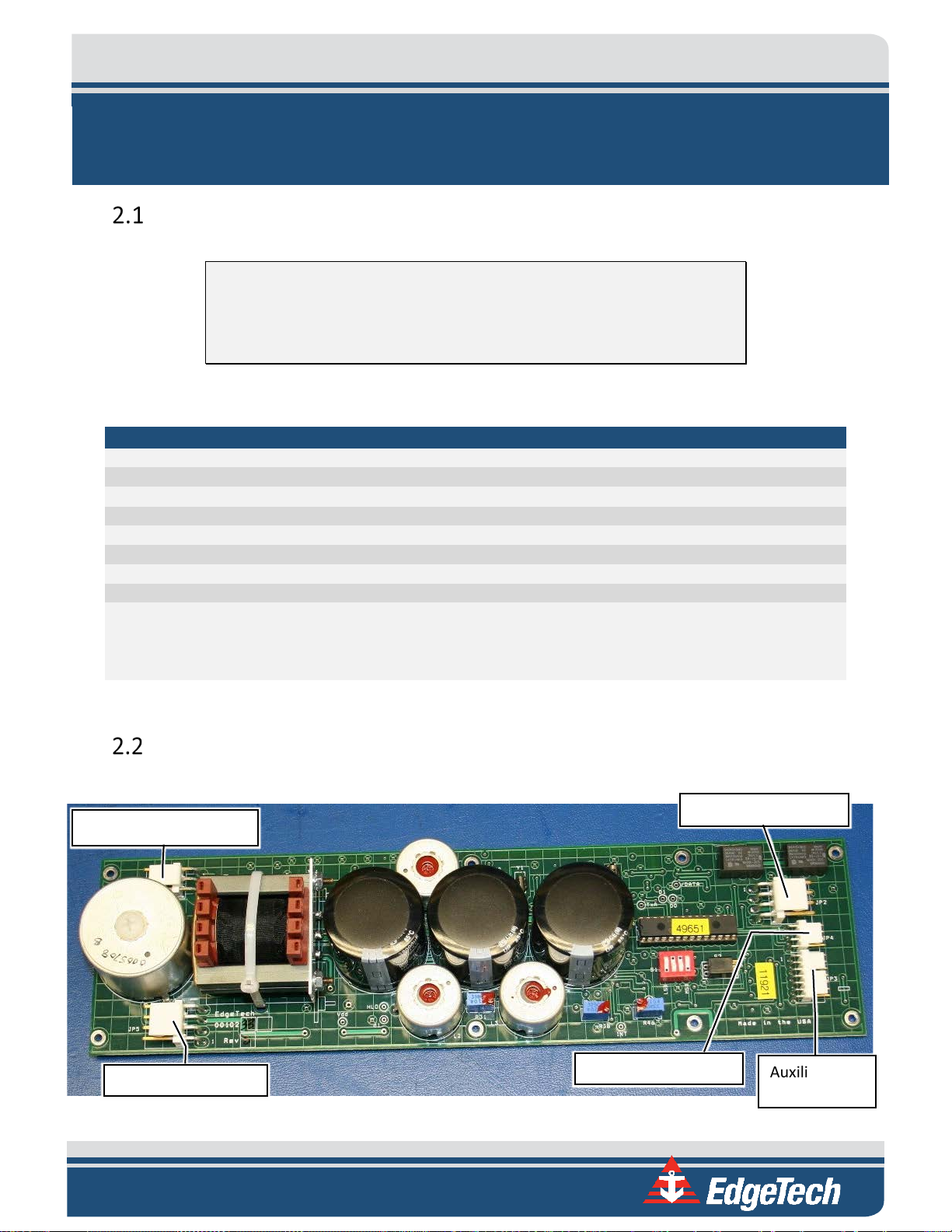
Printed Circuit Board (PCB)
The PCB connectors on the 8242XS board are shown below:
Figure 2-1: PCB Connectors
Page 20

SECTION 2: SPECIFICATIONS 2-2
SPECIFICATIONS
VALUE
Transmit source level
192 dB re 1 µPascal-meter
Command codes
BACS commands
Transponder sensitivity
-80 dB re 1 µPascal
> or = 44 dB re root Hz for jitter < +/- 0.5 milliseconds (3 σT).
Jitter =+/- 0.1 milliseconds for noise-free field
Interrogate frequency
11 kHz (standard unit)
Post filter bandwidth
330 Hz
Minimum interrogate pulse width
5 milliseconds
Reply frequency
Default 12 kHz
Transmit/Reply source level
192 dB re 1 µPascal-meter
Reply pulse width
10 milliseconds (standard unit)
Turnaround time delay
12.5 milliseconds (standard unit)
Lockout time
1.0 seconds
Receiver sensitivity
-100 dB re 1 µPascal-meter
Receiver SNR
> or = 36 dB re root Hz
Receiver type
Hard-limited (2000 Hz / 330 Hz bandwidths)
SPECIFICATION
VALUE
Coding
General to 8000 series – Binary FSK
Allowed tone pairs
Six (see TABLE 2-4) for full breakdown of pairs
Two successive 8 bit words with a 5 sec. interval between them.
Pulse width
22 milliseconds
Period
250 milliseconds
Total command time
9 seconds
Total lockout time
14 seconds re beginning
Total command
capacity per tone pair
Standard functions
Release, Disable Transponder, Enable Transponder
Acoustic Specifications
The acoustic specifications for the 8242XS unit are described in the following sub-sections.
Transponder SNR
Table 2-2: Acoustic Specifications
BACS Command Structure
The BACS’ command structure consists of two 8-bit words separated by a 5-sec interval. Each word is
comprised of 8 bits from a 16-bit command. The 16-bit command is a 15 bit, 11 block cyclic code with an
overall parity bit appended to the end to form a 16-bit code with a minimum Hamming distance of 4 bits.
Two transitions are required within each word, and no repetitions of words are allowed in a command.
Each word comprised of 8 bits from a 16 bit command. The 16 bit command is a 15,
Structure
11 block cyclic code with an overall parity bit appended to the end to form a 16, 11
code with a minimum Hamming distance of 4 bits.
Additionally, two transitions are required within each word, and no repetitions of
words are allowed in a command.
2,000 or 12,000 commands for six tone pairs
Table 2-3: BACS Command Structure Specifications
Page 21
2-3
TONE PAIR NUMBER
“0” (VALUE IN kHz)
“1” (VALUE IN kHz)
2
9.5
10.3
3
9.5
10.7
4
9.9
10.3
5
9.9
10.7
6
10.3
10.7
RELEASE
Activate mechanical release
SPECIFICATIONS
VALUE
2 years & 100,000 replies
4 years & 200,000 replies
BACS Command Coding
BACS command coding is described in the following table:
1 9.5 9.9
Table 2-4: Allowed BACS Tone Pair Breakdown
Standard Command Functions
Functions for the three standard commands are given in the table below:
COMMAND FUNCTION
ENABLE Enable Transponder
DISABLE Disable Transponder
Table 2-5: Standard Command Functions
Environmental Specifications
TEMPERATURE VALUE
Operating
Storage (Batteries Removed)
-10°C to +40°C (14°F to 104°F)
-20°C to +85°C (-4°F to 185°F)
Table 2-6: Environmental Specifications—Temperature
Battery Types
Welded Alkaline pack 2 years & 40,000 replies
Replaceable Alkaline
Replaceable Lithium
Table 2-7: Battery Type Specifications
4.5 years & 250,000 replies
9 years & 500,000 replies
Mechanical Drawings
Mechanical Drawings for the 8242XS are shown below:
Page 22
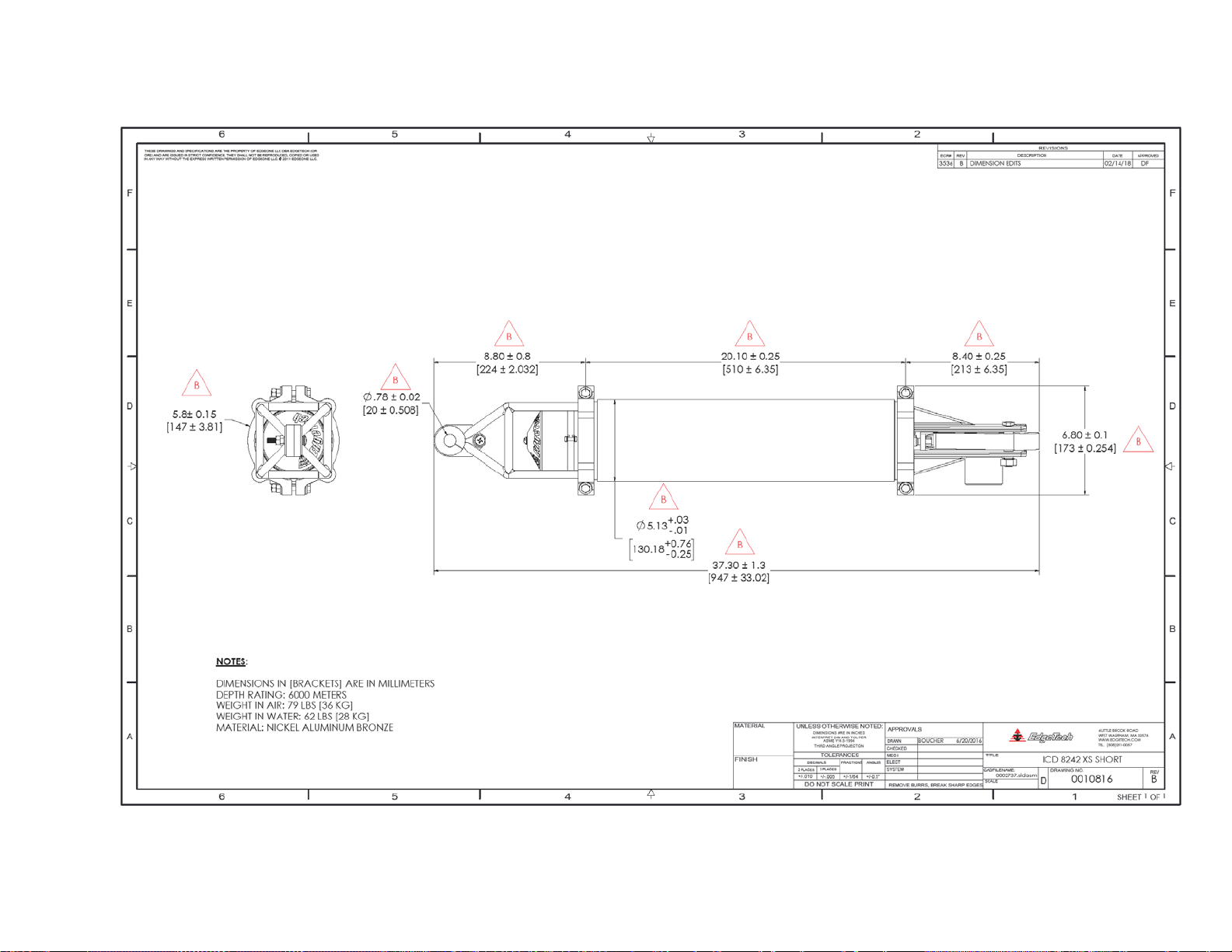
SECTION 2: SPECIFICATIONS 2-4
Figure 2-2: ICD 8272-XS Short – 0010816
Page 23
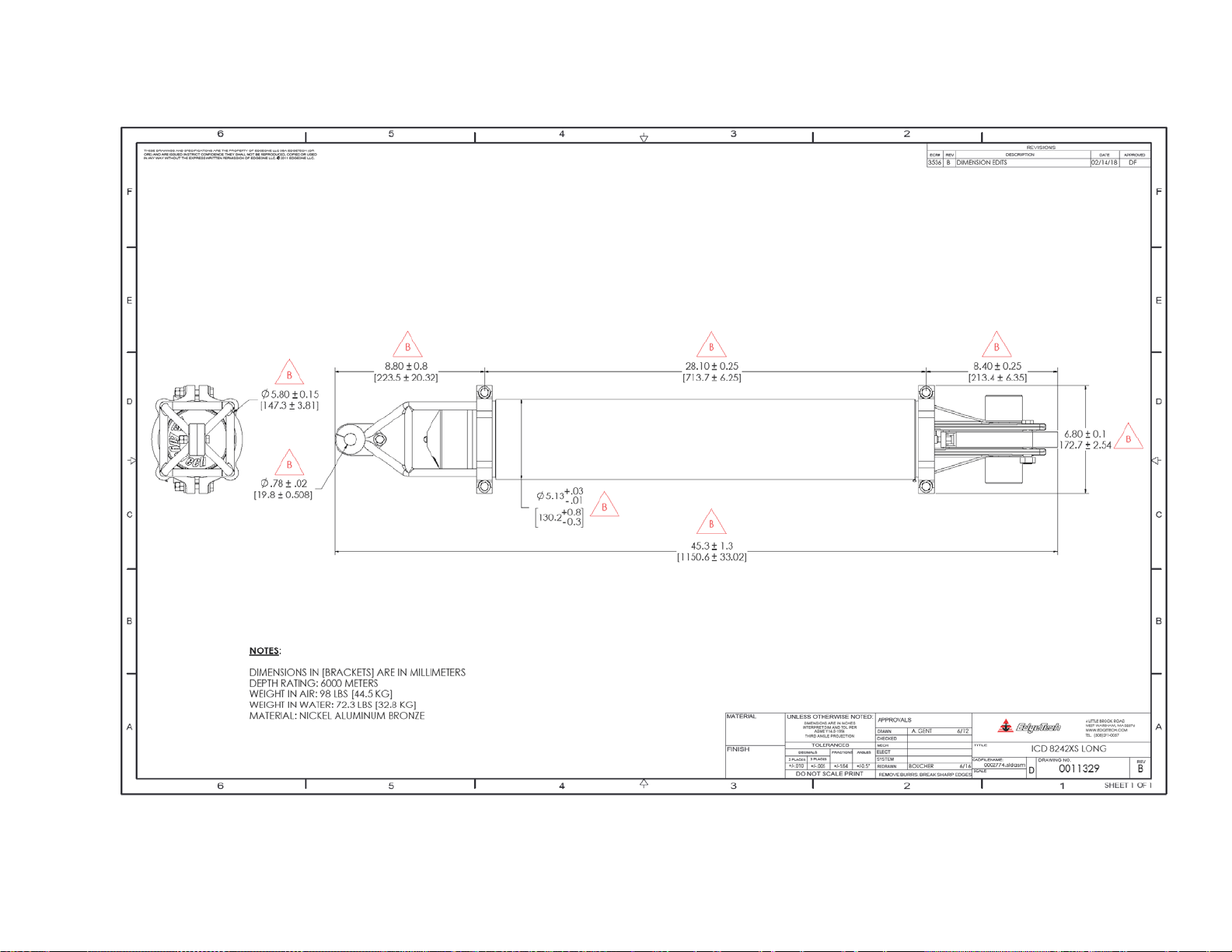
2-5
Figure 2-3: ICD 8242XS Long – 0011329
Page 24

Page 25

3-1
3.0 SETUP AND INSTALLATION
This section contains the information relative to the basic set up and operation of the Model 8242XS
acoustic release. Refer to the specific information sheet that shipped with the unit, for details of its specific
equipment. This sheet includes the 8242XS’s commands, and transponder frequencies.
Acoustic
Efforts should be made to ensure that there is a clear acoustic path between the 8242XS Transducer and
the source (typically a dunking Transducer from a deck unit). Structural elements of a mooring system
which have significantly different acoustic impedance than that of seawater will cause absorption or
reflection of acoustic signals, which will degrade the operation of the unit. Floatation, including glass
spheres, syntactic foam and plastic floats are particularly problematic. Floats placed physically close to
the Transducer can create a blind area in the Transducers beam pattern.
Mechanical
The Release Load is held through the Lifting Support, and Release Hook. There are isolation shoulder
washers on the top pad eye to prevent electrical contact with the mooring. In some installations (such as
a trawl resistant Benthic Landers) the unit needs to be secured to the structure. It is important to verify
that the Release Hook is not obstructed in its motion, which could prevent it from disengaging.
The release mechanism is designed for in-line loads; side loading will severely degrade performance.
Generally, the Release Link is treated as a disposable item. It is used to electrically isolate the release from
the rest of the mooring.
Status Reply
Upon receiving a valid command, the instrument will return a series of pings which are an indication of
the status of the tilt and release sense switches.
The 8242XS is equipped with sensors that monitor the tilted or not tilted orientation of the system. This
information allows the unit to send a coded status reply, based on the instruments orientation and release
state. The tilt status is useful for ascertaining whether the mooring or platform that has been deployed
has landed as planned. At the end of a deployment, the information is useful in determining whether
forces such as strong currents or trawl activity have affected the mooring or platform.
The tilt sensor is a 45° mechanical switch that is mounted on the Release Circuit Board assembly. In the
standard instrument configuration, with the release mechanism down, the unit is defined as “not tilted”.
For applications requiring a narrower maximum allowable angle of tilt optional tilt switches are
available. The switch can also be installed at different angles to change the standard orientation.
Page 26

SECTION 3: SETUP AND INSTALLATION 3-2
15 pings at 2 second intervals
Upright ; Not Released
7 pings at 2 second intervals
Tilted ; Not Released
15 pings at 1 second rate
Upright ; Released
The status reply indicates one of four states:
• "upright (within 45° of upright)" and released
• "upright (within 45° of upright)" and not released
• "tilted (more than 45° from upright)" and released
• "tilted (more than 45° from upright)" and not released
After a command has been received, the unit transmits a series of encoded pings. The 4 possible status
replies are:
PATTERN STATUS
7 pings at 1 second rate Tilted ; Released
Table 3-1: Status Reply Meanings
Page 27

4-1
Purge Port Plug
4.0 OPERATING INSTRUCTIONS
This section of the manual covers instructions for normal operations, including opening and closing the
Transducer End.
To start using the 8242XS, the Housing must be opened so that the battery can be plugged in. The
instructions for this continue below in
The 8242XS is not intended for overhead lifting. Exercise extreme caution
to prevent serious personal injury.
Tools
SUB-SECTION 4.2.
WARNING!
• ½” Socket
• ½” Wrench
• Soft Mallet
Turning the Unit On
8242XS’ are carefully tested and shipped from the factory with a new battery pack installed. Unless
otherwise requested, all battery packs are disconnected in transit, to prolonging the battery life.
To use the 8242XS, the Housing MUST be opened so that the battery can be plugged into the JP5 header
connector on the electronic board. Then, the unit must be closed and the Housing purged.
Removing the Purge Port Plug
Figure 4-1: The Purge Port Plug
Page 28

SECTION 5: MAINTENANCE 4-2
1. Remove the Purge Port Plug Retainer from the Release end of the Instrument by unscrewing the nylon
screw that holds it in place, shown in F
IGURE 4-2.
Figure 4-2: Remove the Purge Port Plug Retainer
2. Equalize pressure by removing the purge port plug, shown in F
IGURE 4-3.
Figure 4-3: Removing the Purge Port Plug
Page 29

4-3
Removing the Lifting Support
1. Remove the three titanium bolts from the top cage-clamp assembly. This must be done carefully.
NOTE: The Bolt at the top of the Cage is shorter than the other two.
CAUTION!
Never put the socket wrench over both nuts when attempting to
removing the Top Nut from the three titanium bolts. This can cause the
nuts to seize together and prevent loosening the bolt.
a. Remove the second nut from each of the three titanium bolts using a ½” wrench and ½”
socket wrench, as shown in F
IGURE 4-4.
Figure 4-4: Removing the (3) Top Nut from the (3) Titanium Bolts
b. Remove the remaining nut from each of the three titanium bolts with the same tools,
using the same method depicted in F
IGURE 4-4.
Page 30

SECTION 5: MAINTENANCE 4-4
2. Place a wrench into the gap between the Cages to pry one side of it off, shown in FIGURE 4-5.
Figure 4-5: Using a Wrench to Pry the Cage Apart
3. With a soft mallet, tap the cages free of the End Cap (two 1/2-inch diameter spreader rods are
loose and will fall free of the cage as it is disassembled).
Figure 4-6: Tapping the Cage Free with a Mallet
Page 31

4-5
Removing the Transducer End
CAUTION!
Take care when removing the Transducer End Cap from the Housing, as
the Transducer is plugged into the Electronics Assembly.
1. Grip the Transducer by its base close to the metal end cap, and pull the Transducer End Cap from
the Housing, taking care not to squeeze or deform the Transducer.
Figure 4-7: Removing the Transducer End Cap
Figure 4-8: The Removed Transducer End Cap
Page 32

SECTION 5: MAINTENANCE 4-6
Applying Power
The Electronics Assembly and Battery Pack are mounted to an aluminum tray, which is attached to the
Release End Cap. Once the Transducer End Cap is removed, the battery can be plugged in.
1. Plug the 4-pin battery connector into the header JP5 on the circuit board. When doing so, ensure
to line the pins up correctly as shown in F
IGURE 4-9 and FIGURE 4-10.
Figure 4-9: Battery Connection Location and One Method for Plugging in the Board
CAUTION!
Ensure the 4-pin battery pack cable connector alignment tabs are
properly aligned with the power connector on the electronics assembly
before pressing into place. If misaligned, damage to the electronics may
occur, rendering the Release unusable until repaired.
Figure 4-10: The Proper Orientation of the Battery Pin Connector and JP5
Page 33

4-7
Closing the Transducer End
Before closing the Transducer End, inspect the O-rings and O-ring mating surfaces and service if needed,
refer to O-R
1. Gently guide the Transducer End cap into the Housing, taking care not to pinch the Transducer
ING SERVICE AND INSPECTION.
CAUTION!
Ensure the 4-pin battery pack cable connector alignment tabs are
properly aligned with the power connector on the electronics assembly
before pressing into place. If misaligned, damage to the electronics may
occur, rendering the Release unusable until repaired.
Cable and Battery Cable. As the O-ring enters the Housing, firm but gentle pressure must be
applied to seat the end cap fully against the Housing as shown in
FIGURE 4-11.
Figure 4-11: Apply Pressure to the Base of the Transducer End to Fully Seat it into the Housing
Page 34

SECTION 5: MAINTENANCE 4-8
Attaching the Lifting Support
Figure 4-12: Cage Assembly for Transducer End Cap
1. Put one side of the cage on. Tap it down softly with a mallet as shown in F
IGURE 4-13.
Figure 4-13: Attach One Part of the Lifting Support
Page 35

4-9
2. Flip the unit over and put the other part of the cage on the top of the unit.
a. Before tapping the other part of the cage with the mallet, align each of the two 1/2-inch
diameter spreader rods into the spaces one at a time, as shown in F
IGURE 4-14.
Note: If inserting the spreader Rods is difficult, remove one part of the
Lifting Support and try again without pushing it down.
Figure 4-14: Applying the Second Part of the Lifting Support, Including the ½” Spreader Rods
b. Gently use a mallet to tap the cage together and try to keep the gaps between the
clamps on both sides even, as shown in F
IGURE 4-15.
Page 36

SECTION 5: MAINTENANCE 4-10
Figure 4-15: Use the Mallet to Ensure the Lifting Support is Securely Attached
CAUTION!
The load capacity is less than 1/10 the rated load if the two 1/2 in. (1.27
cm.) diameter x 4 in. (10 cm.) spreaders are not installed in the cage. The
horizontal members of the cage must form a complete box.
CAUTION!
Ensure the Nylon washers are included in the reassembly procedure and
are placed between the titanium washer and the Support Brackets. They
are vital to the operation of the 8242XS. Refer to FIGURE 5-9.
3. Start by replacing the two titanium bolts on the two sides of the top cage-clamp assembly. Replace
the bolts with only one nut first as shown in F
Figure 4-16: Replace the Two Titanium bolts
IGURE 4-16.
Page 37

4-11
Spreaders (2)
Three sets of 5/16”
Three sets of 5/16”
NOTE: There are two different bolt lengths, the shorter bolt goes into the
Top of the cage.
4. Replace the third titanium bolt on the top cage-clamp assembly. Replace with one nut at a time.
a. It is impossible to use a wrench between the cage, so this is the only time to put the
wrench on the bolt instead of the nuts.
Figure 4-17: Using the Wrench on the top bolt, at the bottom, tighten the first nut.
titanium hardware
titanium hardware
with nylon
with nylon
shoulder washers
shoulder washers
between titanium
between titanium
and bronze.
and bronze.
Figure 4-18: Top End Cap Completed Assembly
Page 38

SECTION 5: MAINTENANCE 4-12
Replace the Purge Port Plug
CAUTION!
Before reinserting the Purge Port Plug, ensure it is clean and free of
debris. Even small debris can cause the unit to flood.
Note: The shoulder on the Purge Port Plug is approximately flush with the
end cap when it is inserted fully and the glass epoxy retainer is wrapped
around the .19-inch diameter stub
1. Purge the instrument as per the following sub-section 4.2.
2. Replace the Purge Port Plug as shown in F
IGURE 4-19.
Figure 4-19: Replace the Purge Port Plug
3. Replace the Purge Port Retainer using the nylon screw as shown in F
IGURE 4-20.
Figure 4-20: The Replaced Purge Port Plug Retainer
Page 39

4-13
Leak Detection and Condensation Prevention
EdgeTech 8242XS releases are provided with a 3/8-inch diameter purging port in the Clevis End Cap. The
following procedure assumes the user has a vacuum pump, dry nitrogen gas cylinder, and compound
pressure/vacuum gauge all arranged on a manifold setup. The recommended procedure for preparation
of the instruments atmosphere is as follows:
After checking that all other ports are sealed, draw a near -3 PSIG vacuum via the purging port. Verify with
a gauge that the release holds the vacuum. Backfill with dry nitrogen then draw a near -3 PSIG vacuum.
Quickly insert the purging plug before the -3 PSIG vacuum is lost. If the environment where the release
was assembled was very humid then repeat the purging procedure 2 to 4 times before replacing the plug,
to remove all moisture.
1. Verify that all (except purge port) O-ring seals have been cleaned, lubricated and assembled.
2. Prepare the purge port plug for installation by cleaning and greasing it, the plug must be ready for
immediate insertion.
3. Insert a purge port adaptor and draw a -3 PSIG vacuum, do not exceed -5 PSIG.
4. Close the manifold valve to the instrument and allow the instrument to sit for 15 minutes. Check
the gauge afterwards and verify that the vacuum did not change. This step is done to detect gross
O-ring problems (cut or missing).
5. Open the valve to the instruments purge port and:
a. Backfill the Housing with dry nitrogen gas, do not exceed +5 PSIG.
b. Draw a -3 PSIG vacuum on the instrument, do not exceed -5PSIG.
c. In humid environments, you should repeat this process up to four times.
d. After drawing the final vacuum in this process, remove the purge hose and quickly insert
the purging plug before the -3 PSIG vacuum is lost.
e. Replace the Purge Port Plug Retainer with the instructions in subsection 4.1.7.
Note: If the environment where the release was assembled was very
humid then repeat the purging procedure 2 to 4 times before replacing
the plug, to remove all moisture.
CAUTION!
When purging the instrument, be careful not to draw more than -5 PSIG
vacuum. Exceeding this figure can damage the battery or electronic
components, which in turn can result in instrument failure. If a purging
set up is not available, then place a desiccant pack inside the Housing to
help reduce moisture.
Page 40

SECTION 5: MAINTENANCE 4-14
Arming the Instrument
The release mechanism is easily armed using only the slotted arming tool that is provided with the system.
No disassembly is required even after multiple firings (except for battery replacement).
Figure 4-21: Clevis Rotation Drawing
The Model 8242XS release is designed to be used with the EdgeTech Release Link. The release link will
accept a standard 5/8inch shackle (maximum .77in [1.9 cm.] pin diameter and minimum 1.06in [2.7 cm.])
opening. The external moving components of the release mechanism are shown in F
IGURE 4-22.
Page 41

4-15
T-Shaped Release Shaft
Zinc Anode
Release Link
Release Hook
Slotted Release Latch
Figure 4-22: The Armed 8242XS
Page 42

SECTION 5: MAINTENANCE 4-16
To Arm the Instrument:
1. When capturing the anchor link in the hook, be sure to support the Anchor Link and the Hook.
pivoting the latch back over the T-Shaft.
Figure 4-23: The Release Link Captured by the Release Hook
Capture the end of the hook behind the latch while passing the slot in the latch down over
2.
the T-shaft, as shown in
FIGURE 4-24.
Figure 4-24: Capture the End of The Hook onto the Latch Recess
Page 43

4-17
3. Using the slotted arming tool, rotate the shaft clockwise until the internal mechanism ‘clicks’ and
holds position. DO NOT FORCE THE MECHANISM FURTHER THAN NEEDED (approximately 40-inch-
pounds torque is required to rotate the shaft 30 degrees clockwise).
CAUTION!
The Release Mechanism is armed after rotating the shaft. Do not attempt
reverse rotation with the arming tool. Forced reverse rotation will
jeopardize optimum performance.
Figure 4-25: Rotating the Shaft Using the Arming Wrench
Page 44

SECTION 5: MAINTENANCE 4-18
Figure 4-26: The Armed T-Shaft
Release Function
After the RELEASE command has been decoded, the power supply is switched on to the motor. The
internal torsion spring is released by the motor and provides torque to the t-shaped release shaft. When
the T-shaped end of the shaft turns and aligns with the slot in the latch, a release will occur. The shaft
carries a small percentage of the mooring tension along its axis with support via two thrust washers at the
top (inside end) of the shaft.
The torque created by the spring needs to overcome the friction between the shaft and the latch. Because
the torque generated by the spring is a fixed quantity, the electrical current requirement of the motor is
purely a function of the size of the spring. The central design parameter of the mechanical release
assembly is the size (magnitude) of the spring force. The effective battery life is based on the minimum
voltage required to release the spring and the maximum release capability is defined by the mooring
tension frictional force that the spring must overcome.
Page 45

4-19
Release Latch Inspection (following high load in-air releases):
It should be routine practice after any release (air or water) to inspect the release latch and release latch
pin for flatness. In the absence of the damping effect of water or if very high loads are released, the hook
latch and Release Hook exhibits significant dynamics.
When testing the release in air, the hook and latch will strike one another. Slight bending of the latch or
latch pin (a few thousandths of an inch) may occur. Bending greater than .002-inch in the latch or pin will
impair the release performance and may warrant replacement of the bent part. To prevent binding during
in-air tests, bond a 3/8-inch thick by 2-inch long strip of rubber to the hook. This will absorb the shock of
impact when the latch strikes the hook. This is only necessary if a heavy load will be used for the test.
ON/OFF Option
When the On/Off Option is included, the instrument may be fully prepared and sealed before powering
the electronics. The power supply is an open loop until the On/Off Actuator Plug is fully inserted. The
On/Off Actuator Plug is a keyed four-pin plug that closes the power supply circuit when it engages the
connector inside the instrument.
WARNING!
NEVER twist or attempt to rotate the On/Off Actuator Plug, as this may
break the male connector pins inside the On/Off Mechanism.
There are two proper alignment positions of the 1/8-inch milled slot on the top of the On/Off Actuator
Plug. For Releases machined prior to the year 2000 the 1/8-inch milled slot on the top of the On/Off
Actuator Plug pointed away from the center of the end; and for Releases manufactured after 2000 the
1/8-inch milled slot on the top of the On/Off Actuator Plug pointed to the bottom left, approximately 200
degrees from the top center position. Both alignments are shown in F
IGURE 4-27.
Figure 4-27: The Two Possible On/Off Actuator Plug Positions
Page 46

SECTION 5: MAINTENANCE 4-20
On/Off Actuator
Purge Port Plug
OFF Position
ON Position
Milled Slot
Figure 4-28: On/Off Actuator Plug on the Clevis End
Figure 4-29: The ON and OFF Positions of the On/Off Actuator Plug
On/Off Instructions
Turning the On/Off Actuator On and Off is extremely simple. If this option was purchased, follow the
instructions below. If this option was not purchased, disregard this section, as the On/Off Actuator Plug
was replaced with a Dummy Plug.
Note: When powered on, the On/Off Actuator Plug is approximately flush
with the End Cap and the epoxy retainer is wrapped around the .19-inch
diameter stub, as shown in FIGURE 4-29.
Page 47

4-21
4.5.1.1 On Instructions
1. Loosen Retainer, and move it out of the way, as shown in FIGURE 4-30.
Figure 4-30: Loosen the Retainer and Move It Out of the Way
2. Push On/Off Actuator Plug in. This will turn the On/Off Option ON, as shown in F
Figure 4-31: Push in the On/Off Actuator
3. Return Retainer to its proper position and tighten it, as shown in F
IGURE 4-32.
IGURE 4-31.
Figure 4-32: Return Retainer and Tighten
Page 48

SECTION 5: MAINTENANCE 4-22
4.5.1.2 Off Instructions
1. Loosen Retainer, move it out of the way, as shown in FIGURE 4-30.
2. Pull the On/Off Actuator Plug out so the off position groove is flush with the unit, as shown in
F
IGURE 4-33. This will turn the On/Off Option OFF.
Figure 4-33: Pull the On/Off Actuator Out
3. Return Retainer and tighten, as shown in F
IGURE 4-32.
Page 49

4-23
Air Acoustic Testing
CAUTION!
Do not exceed -3 PSIG while purging the housing, as an excess vacuum
can damage the batteries.
Always perform an air acoustic test of the commands and interrogate the instrument after assembling to
assure proper working order. Every time the instrument is powered up, repeat the air acoustic test to
assure proper engagement of the On/Off plug. Place the deck box transducer within 1 meter of the
underwater unit transducer when sending commands. The position of the transducers relative to one
another may need to be adjusted to allow commands to get through in air. Ranges will not be accurate in
air; these systems are designed to operate in water. The speed of sound in air can cause errors in
command decoding and prevents accurate ranging however the systems can be tested in air. Test all
functions of the system by sending each command and verifying that the state changed according to the
command including status reply.
Setup
The specific acoustic impedance of air is quite different from that of seawater, which renders the
Transducer a far less efficient receiver when out of water. For this reason, it is necessary to place the
source (Deck Unit Transducer) within a meter or two of the 8242XS Transducer, with no obstructions to
the acoustic path. Depending on the environment, some experimentation may be necessary to find a
suitable location.
Tests
For the following tests, it will be necessary to have the proper six digit commands unique to the unit being
tested. If it appears that commands are not getting through, verify that the serial number of the unit being
tested matches that on the sheet of command codes.
Using a deck unit, ascertain whether the 8242XS is enabled or disabled by interrogating it if the unit has
just been powered up it will be enabled. Unless otherwise specified, the 8242XS will be shipped from
EdgeTech with the interrogate frequency tuned to 11 kHz and the reply frequency set to 12 kHz.
a. Upright and Not Released: 15 pings at a 2 second rate
b. Tilted and Not Released: 7 pings at a 2 second rate
c. Upright and Released: 15 pings at a 1 second rate
d. Tilted and Released: 7 pings at a 1 second rate
Page 50

SECTION 5: MAINTENANCE 4-24
1. Arm the release and orient it horizontally. Using the deck unit, send the ENABLE command. The
instrument should reply with a series of 7 pings at a 2 second rate indicating the instrument is
tilted more than 45 degrees and not released.
2. Send the RELEASE command. The instrument should release and reply with a series of 7 pings at
a 1 second rate indicating the instrument is tilted more than 45 degrees and has released.
3. Interrogate the instrument using the Deck Unit set at the appropriate interrogate frequency for
the release being tested and tuned to the proper reply frequency.
It is unlikely that the Deck Unit will display a valid range because it is being tested in air, but you
should be able to verify that the instrument transmits a reply pulse by listening to the alarm on
the front panel of the Deck Unit.
4. Orient the release vertically (Transducer up) and send the DISABLE command. The instrument
should reply with a series of 15 pings at a 1 second rate indicating released and tilted less than 45
degrees. Now range on the instrument again with the deck unit. This time the unit should not
transmit a reply pulse.
It is good practice DISABLE the release after deployment, as ambient noise sources could run down the
battery.
Post Deployment
After recovery, the Unit should be cleaned and rinsed with fresh water to avoid salt buildup and
deterioration of mechanical parts.
A visual inspection of the Housing and release mechanism should be performed to detect any signs of
damage, excessive wear, corrosion, etc.
If the 8242XS is not to be used again soon, the Unit should be turned off (battery unplugged - follow
procedure described in sub-section 4.1).
If the Unit is to be stored for a long period of time, the batteries should be removed. See Maintenance
procedures in
SECTION 6: MAINTENANCE.
Page 51

5-1
5.0 MAINTENANCE
The 8242XS requires minimal maintenance. Pre-deployment preparations and checks, and postdeployment cleaning will fulfill most of the maintenance requirements. The important tasks are battery
replacement, 'O' ring care and maintenance, and general cleaning, inspection, and lubrication of
operational elements.
Housing and Release Preparation and Care
To access the electronics assembly or mechanical assemblies, remove the five sets of titanium hardware
holding the upper and clevis End Caps in place, as shown in F
The 8242XS releases are shipped with 12 PSIA (-2.5 PSIG) of dry nitrogen, which reduces moisture in the
housing and helps to seat the O-Rings. Equalization of pressure by removal of the purge port plug will be
necessary to gain entry into the instrument.
IGURE 5-6.
WARNING! If the underwater unit has been deployed, there is the
possibility of leakage and internal pressurization of the housing. If the
housing is pressurized, be sure to exercise extreme caution when
relieving the pressure. The resulting violent motion of some parts can
result in serious personal injury.
NOTE: In some releases the cable from the electronics to the transducer
is short (12 inches (30 cm.)). To prevent parting the cable, always remove
the top (transducer) end cap first, and disconnect the transducer from
the electronics.
WARNING! High voltage is present at this connector when the unit
transmits reply bursts.
Page 52

SECTION 5: MAINTENANCE 5-2
Transducer Cable
Battery Cable
To Open the 8242XS
Should the need arise for service or replacement of parts, the following instructions detail complete
disassembly and reassembly of the Unit. These instructions will build upon the instructions in section
as they follow some of the same initial steps, but are more in depth.
NOTE: It is essential that the nickel-aluminum bronze material be isolated
from any dissimilar metal. Because of this, the instrument is supplied with
a disposable anchor link with nylon insulating bushings. This link or its
equivalent must be used to prevent harmful galvanic corrosion between
dissimilar metals.
Tools
• ½” Socket
• ½” Wrench
• Soft Mallet
4.1,
8242XS Disassembly
To Disassemble the 8242XS:
1. Remove the Purge Port Plug, referring to sub-section
2. Remove the Lifting Support, referring to sub-section 4.1.2.
3. Remove the Transducer End, referring to sub-section 4.1.3.
4.1.1.
Figure 5-1: The Plugged in Battery and Transducers Cables
Page 53

5-3
4. Disable power supply by disconnecting the connector from the battery pack to the main board.
Note: Always unplug the Battery before unplugging the Transducer Cable.
5. Disconnect the transducer cable.
Figure 5-2: The Unplugged Battery and Transducer Cables
Page 54

SECTION 5: MAINTENANCE 5-4
Remove the Clevis End Cap
4. Remove the two titanium bolts from the lower clamp assembly. This must be done carefully.
Follow the sub-steps below:
CAUTION!
Never put the socket wrench over both nuts when attempting to
removing the Top Nut from the three titanium bolts. This can cause the
nuts to seize together and prevent loosening of the bolt.
a. Remove the second nut from each of the three titanium bolts using a ½” wrench and ½”
socket wrench, as shown in F
IGURE 4-4.
Figure 5-3: Removing the (2) Top Nut from the (2) Titanium Bolts
b. Remove the remaining nut from each of the three titanium bolts with the same tools,
using the same method depicted in F
IGURE 5-3.
Page 55

5-5
5. Place a wrench into the gap between the two parts of the Clevis End Cap to pry one side of it off,
shown in F
IGURE 5-4.
Figure 5-4: Using a Wrench to Pry the Clevis End Cap Apart
6. With a soft mallet, tap the other half of the clamp to free the End Cap.
Figure 5-5: Tapping the other end of the clamp with a soft Mallet
Page 56

SECTION 5: MAINTENANCE 5-6
CAUTION!
When removing the Release End Cap Assembly with the electronics
attached, take care to pull the chassis out straight and not drag the
chassis edge on the housing bore seal.
6. Remove the Release End Cap by carefully sliding the Electronics Assembly out of the Housing.
Take care not to scratch the O-ring surfaces, shown in F
IGURE 5-6.
Figure 5-6: The Electronics Assembly Completely Removed from the Housing
Page 57

5-7
8242XS Assembly
The instructions below detail the Clevis End Cap Assembly.
Clevis End Cap Assembly
1. Prepare the sealing surfaces for assembly by cleaning with a lint-free towel or swab, moistened if
needed with alcohol. Inspect for scratches or nicks which will impair the O-ring efficiency. Apply
a Very light coat of O-ring lubricant (EdgeTech recommends the use of Parker Super O-lube) to
the piston O-ring surface to aid sliding insertion of the piston seal. Inspect the O-Rings for damage
or manufacturing flaws such as tears, dimples or inclusions in the rubber. Lightly coat the O-Rings
with O-ring lubricant. Protect O-Rings when stretching them over large diameters (i.e., cover
diameter. with plastic sleeve). See F
Only a light coating of lubricant is required. Excess lubricant between
seals may cause excessive hydraulic pressure between O-Rings, resulting
in improper seating.
IGURE 5-7, FIGURE 5-9, and FIGURE 4-12.
CAUTION!
Figure 5-7: O-Rings in Clevis End Cap
2. Slip the electronics into the housing. After the electronics is in the housing and before the
transducer end cap is inserted, connect the transducer cable and then the battery.
CAUTION!
Do not pinch or damage wires when inserting assembly into the housing.
There are large diameter plates in the electronics assembly which will not
allow clearance for cables or connectors.
3. Carefully press the piston seal into the housing. The backup O-ring is properly aligned if it enters
the housing before the O-ring while the curved side of the backup ring faces the O-ring.
Page 58

SECTION 5: MAINTENANCE 5-8
Figure 5-8: Cross Section of the Face Seal, Gland, and Back-up O-Rings
4. When the End Cap flange mates against the housing, be sure the O-ring is properly seated in the
groove and is not crushed outside the groove between the end cap and housing.
5. The end cap is secured to the housing by gently starting one of the clamps onto the 15-degree
tapered flanges. After both sides of the clamp have been started, seat the clamp with
progressively sharper taps using a soft mallet. Clamping hardware includes 5/16” titanium nuts,
bolts and washers, are shown in F
IGURE 5-9.
NOTE: Nylon shoulder washers, also included, are essential and must be
positioned between the titanium and bronze to prevent damaging
galvanic corrosion of the bronze, as shown in FIGURE 5-9.
Page 59

5-9
(2) Titanium Hex Nuts
Titanium Hex Head Bolt
Nylon
Washer
Titanium
Washer
Nylon
Washer
Titanium
Washer
Shoulder
Shoulder
Figure 5-9: Clamping Hardware
6. Continue tapping all parts of both clamps with the soft mallet until no further tightening of the
hardware is possible. Use a torque wrench if available and torque all five of the titanium fasteners
to between 175 and 200 in. lbs. (200-230 centimeter kilograms).
Battery Replacement
Remove the electronics chassis from the housing according to the disassembly procedure. Make sure that
the battery connector is disconnected from the board and remove the brackets which hold the battery
pack to the aluminum plate. Discard the old battery. Install the new battery and replace the brackets
which hold it in. Route the battery connection in such a way that it will not be crushed when assembling
the electronics in to the housing. After replacing the batteries, the user is advised to perform an air
acoustic check of the release. Assemble the electronic chassis in the release housing.
Page 60

SECTION 5: MAINTENANCE 5-10
Battery Replacement Procedure
There are three different replacement battery options:
WARNING!
IF THE UNDERWATER UNIT HAS BEEN DEPLOYED, THERE IS THE
POSSIBILITY OF INTERNAL PRESSURIZATION, EXERCISE EXTREME
CAUTION WHEN OPENING THE INSTRUMENT!
CAUTION!
The 8242XS’ Battery Pack is on the underside of the Electronics’
Assembly. To replace the battery, the Electronics board must be flipped
upside down. This is safe. No components will touch the table if properly
handled. Battery replacements should always be done on a hard surface,
such as a table or work bench to prevent damage to all components.
When replacing the battery, take special care to install the Battery
Connection Wires to avoid pinching them with the Battery Pack Retaining
Brackets during reassembly.
To Replace the Batteries:
1. Open the instrument, referring to sub-section 4.1.1.
2. Remove the Lifting Support, referring to sub-section
4.1.2.
3. Open the Transducer End from the Housing by gently pulling them apart. Be careful not to scratch
the Housing then pulling the assembly from the tube, referring to sub-section 4.1.3. Do not
advance to 4.1.4.
4. Disconnect the Battery Cable from the Electronics Assembly (JP5), as shown in F
5. Disconnect the Transducer Cable from the Electronics assembly (JP1), as shown in
IGURE 5-10.
FIGURE 5-10.
Page 61

5-11
Battery Cable
Transducer Cable
Battery Pack Retainer
Brackets Screws (4)
Battery Pack Retainer Brackets (2)
Figure 5-10: The Plugged in Battery Cable and Transducer Cable
6. Remove the Clevis End, referring to sub-section 5.2.2.
7. Remove the four screws that connect the Battery Pack retaining brackets to the electronics chassis
as shown in
FIGURE 5-11. There are two screws on each Battery pack retaining bracket.
NOTE: Before removing the Retainer Brackets and Screws, be sure to
note the orientation of the wires. The wires MUST be inserted the same
way to avoid being pinched or damaged by the retainer brackets, which
may result in Unit failure.
Page 62

SECTION 5: MAINTENANCE 5-12
Figure 5-11: The Battery Pack is on the Underside of the Electronics Chassis
8. Remove the old Battery Pack and properly dispose of it in accordance with local environmental
guidelines.
9. Install new Battery Pack on the plate and install the retaining brackets, as shown in F
Figure 5-12: Close-up view of the (4) Bracket Screws and (2) Retainer Brackets
IGURE 5-12.
10. Assemble the instrument, refer to sub-section 4.1.5.
Battery Replacement Considerations
Note: It is critical that new batteries be installed with the utmost care,
failure to do so will result in instrument failure.
For Releases that use the replaceable alkaline or Lithium battery options, the user should exercise care in
selecting replacement batteries. Check both the polarity and open circuit voltage of each cell. EdgeTech
recommends: for Lithium Units Tadiran type TL-5920/S batteries. For Alkaline Units Energizer EN93 Type
batteries.
Note: It is not possible to estimate the remaining capacity by measuring
its open circuit voltage.
Page 63

5-13
5.4.2.1 Battery Replacement
1. Remove the electronics chassis from the housing according to the disassembly procedure. Ensure
the battery harness is disconnected from the circuit board (Connector JP5). The batteries are
housed in Delrin battery holders, there are six batteries per holder. Each holder has an Aluminum
cover plate that is held in place by four, #4-40 screws.
2. Sequentially remove the four cover plate screws from each holder and set them aside. The battery
strings are forced together by spring loaded contacts on the holders ends. Pry the middle cells out
then side out the adjacent cells. Dispose of the old batteries in accordance with local regulations.
To prevent contact contamination, each cell and each battery contact must be cleaned just prior to cell
installation. EdgeTech recommends using rubber gloves while changing batteries.
3. Burnishing the contacts. The recommended cleaning procedure calls for first burnishing the
contact areas with a soft pencil eraser.
4. After burnishing, the contact area needs to be wiped clean with a Kim wipe and Isopropyl alcohol
and then Lithium Based Mechanical / Electrical Grease (L260np high drip point) [PN 0012744]
should be applied to battery contact surfaces.
NOTE: After cleaning and applying the grease, do not touch the contact
area or allow it to come in contact with anything.
5. Carefully insert the new, cleaned batteries into the holders. Each battery holder has a label
indicating battery orientation. Ensure the battery alignment matches the label.
6. Install the battery holder cover plate using the previously removed four, #4-40 screws.
7. Once all the battery holders have been loaded with new cells, use a DVM to test each battery
string for continuity.
8. Measure across the back exposed ends of the battery contacts. These contacts are gold plated
and are located on the circuit boards on the ends of the battery holders.
At 20 degrees C, each string of batteries should measure approximately:
• 10.89 volts for the Lithium battery packs
• 4.77 volts for the Alkaline battery packs
NOTE: For Alkaline Battery packs, 4.77 Volts is half of the packs potential,
the two strings are connected in series.
After reassembly, EdgeTech recommends purging the Release with dry Nitrogen, ensuring the batteries
and electronics are operating in a dry, inert atmosphere. Refer to the P
URGING INSTRUCTION.
Page 64

SECTION 5: MAINTENANCE 5-14
O-Ring Considerations
The 8242XS End Cap assemblies use a standard O-ring to provide watertight integrity to the Electronics
Housing. Under normal usage, proper care, and lubrication, the O-ring should provide several years of
usage. However, like the batteries, the O-ring is an inexpensive component, which is absolutely critical to
the successful operation of the entire system. Depending on the frequency of use, it is a good practice to
periodically replace the O-ring. It is essential to inspect the O-Rings and sealing surfaces before and after
each deployment.
Prepare the sealing surfaces for assembly by cleaning with a lint-free towel or swab, moistened (if needed)
with alcohol. Inspect for scratches or nicks which could impair the O-ring’s ability to provide a seal. Apply
a light coat of O-ring lubricant (EdgeTech recommends Parker Super O-lube, be sure to use only silicone
grease) to the Housing and O-ring to facilitate insertion of the end cap. Make sure the lubricant is
compatible with Nitrile rubber. Inspect the O-ring for damage such as tears, dimples, or other defects in
the rubber. Replace any O-ring that is questionable or old. Lightly coat the O-ring with lubricant. Protect
O-Rings when stretching them over large diameters.
CAUTION!
Applying too much lubricant to the O-ring can compromise the seal.
CAUTION!
The ends of the housing are O-ring seating surfaces. They must be
protected while the unit is disassembled. Any scratches will impair the
performance of the O-Rings and may result in leaks.
Additional O-Rings
There are additional O-Rings that provide the watertight integrity to the Housing. These are located on
the Purge Port, T-Shaft, and On/Off Actuator Plug or Dummy Plug. Check and replace these O-Rings
periodically.
O-Ring Service Disassembly
If you are servicing O-rings or wish to inspect the Release End:
1. Follow the disassembly instructions in 8242XS
DISASSEMBLY.
2. Clean, Inspect, and lightly Grease the O-rings as shown in
5-15. EdgeTech recommends the use of Parker Super O-lube, be sure to use only silicone grease.
FIGURE 5-13, FIGURE 5-14, AND FIGURE
Page 65

5-15
Face Seal O-Ring
Face Seal O-Ring
Gland O-Ring &
Backup O-Ring
Gland O-Ring &
Backup O-Ring
Figure 5-13: The Transducer End O-Rings
Figure 5-14: The Release End O-Rings
Figure 5-15: The Purge Port Plug O-Rings
Page 66

SECTION 5: MAINTENANCE 5-16
General Cleaning and Inspection
Whenever the Unit has been recovered from a deployment, the Unit should be cleaned and rinsed with
fresh water to avoid salt buildup and deterioration of mechanical parts. A visual check of the Housing and
release mechanism should be performed to detect any signs of damage, excessive wear, corrosion, etc.
Inspection Particulars
• Check the condition of the Release Arm
• Check for corrosion of the Purge Plug
o Inspect and replace the two O-Rings on the Purge Port Plug, as needed
• Check and replace if needed all O-rings
o Each End Cap has three O-rings: a Gland O-ring, a flat, back-up O-ring, and a face seal O-
ring. The inner O-ring is the flat backup O-ring, the curved surface should be facing the
outer gland O-ring and toward the endcap. The Face Seal O-Ring is independent and
always by itself. Both O-rings need to be in the correct position and properly lubricated
to ensure water tight integrity.
• Check and replace the (8) O-Rings mentioned above, if needed.
Figure 5-16
: Cross Section of the Face Seal, Gland, and Back-up O-Rings
• Check and replace the Anode, if needed
• Check the Housing for signs of corrosion or damage to the hard coat.
o If there is paint damage on the outside of the Release, use an epoxy based paint to seal
the surface
Page 67

5-17
QTY
DESCRIPTION
EDGETECH MTL NUMBER
1
ANODE 8242 XS 2.36 INCH 1.75 INCH ZINC
MTL 1
8
HARDWARE BOLT STD MACHINE HEX HD 5/16 18 2.25 INCH TI
MTL 3
20
HARDWARE WASHER STD FLAT 0.3125 ID 0.75 OD 5/64 THICK TI
MTL 4
2
HARDWARE BOLT STD MACHINE HEX HD 5/16 18 1.75 INCH TI
MTL 5
20
HARDWARE NUT STD HEX 5/16 18 TI
MTL 6
2
ASSY TOP LINK ANCHOR 8242 RELEASE
MTL 7
4
ASSY TOP KIT SPARES BACS O RING
ASM 8
1
LUBRICANT GREASE SILICONE
MTL 9
20
HARDWARE WASHER STD SHOULDER 0.3125 INCH 0.75 INCH BARREL NYLON
MTL 10
2
PLUG RETAINER 8242 G10 FIBERGLASS
MTL 12
1
LATCH 8242 XS SWITCH ACTUATOR G 10 6000M
MTL 13
4
HARDWARE SCREW STD PAN HD PHILLIPS 8 32 0.3125 INCH NYLON
MTL 14
6
BUSHING INSULATOR 8242 XS 0.07 THICK DELRIN
MTL 15
2
SPACER 8242 LIFTING SUPPORT G 10 FIBERGLASS
MTL 16
1
PLUG PURGE 8242 NAB 6000M
MTL 17
PART
SERVICE / INSPECTION
REPLACEMENT
NOTES
Any questionable O-ring should be immediately replaced.
Battery Pack
Before Each Deployment
As needed
Before and After Each
The Release Link is sacrificial and must be replaced after each
Release Shaft
The anode should be replaced if chipped, damaged, or has
Purge Port
Before and After Each
Should not be
General Inspection and Replacement Schedule
This chart is for customer convenience and gives general guidelines for inspection and suggested
replacement times for key parts. Regular inspections and cleaning are vital and should be done in tandem.
O-ring
Release Hook
Release Link Before Each Deployment Per release
O-Ring
Anode After Each Deployment As needed
Retainer
Before and After Each
Deployment
Deployment
As needed Check after 3-5 years Contact EDGETECH CUSTOMER SERVICE for replacement
Deployment
As needed
As needed
needed
Table 5-1: General Inspection and Replacement Schedule
Field Service Kit
EdgeTech recommends the use of Parker Super O-lube silicone
compound grease.
deployment. The Release Link is not sacrificed in Tandem
Assemblies.
degraded significantly from its original size.
Table 5-2: Field Kit – 0003102
Callout Assembly Drawings
Callout Assembly Drawings for the 8242XS are shown below.
Page 68

SECTION 5: MAINTENANCE 5-18
Figure 5-17: 8242XS MART Main Sub Assembly – 0002737
Page 69

QTY
DESCRIPTION
EDGETECH MTL NUMBER
1
ASSY TOP DUCER 8242 XS ACOUSTIC RELEASE
ASM 1
1
ASSY SUB ELECTRONICS 8242 XS RELEASE
ASM 2
1
PCB ASSY TOP MAIN BOARD ANALOG F3 HIGH BAND BART
ASM 3
1
ASSY SUB RELEASE MECHANISM 8242 XS
ASM 4
5-19
0002737 BOM
This table depicts the Material Call outs in FIGURE 5-17: 8242XS MART MAIN SUB ASSEMBLY – 0002737
Table 5-3: 0000002737 BOM
Page 70

SECTION 5: MAINTENANCE 5-20
Figure 5-18: 8242XS Release Sub Electronics Release Assembly – 0002650
Page 71

QTY
DESCRIPTION
EDGETECH MTL NUMBER
1
HOUSING PRESSURE 8202 / 8242 MACHINED & PAINTED 20 INCH NAB 6000M
MTL 1
2
WELDMENT 8242 LIFTING SUPPORT ASB
MTL 2
2
CLAMP END CAP 8242 MACHINED HEAT TREATED
MTL 3
2
O-RING BUNA-N 70 2-245 STANDARD ROUND BLACK
MTL 4
2
O-RING BUNA-N 70 2-240 STANDARD ROUND BLACK
MTL 5
2
O-RING BUNA-N 90 8-240 BACKUP PARBAK ROUND BLACK
MTL 6
1
ANODE 8242 XS 2.36 INCH 1.75 INCH ZINC
MTL 7
1
HARDWARE BOLT STD MACHINE HEX HD 5/16-18 1.75 INCH TI
MTL 8
4
HARDWARE BOLT STD MACHINE HEX HD 5/16-18 2.25 INCH TI
MTL 9
10
HARDWARE WASHER STD SHOULDER 0.3125 INCH 0.75 INCH BARREL NYLON
MTL 10
10
HARDWARE WASHER STD FLAT 0.3125 ID 0.75 OD 5/64 THICK TI
MTL 11
10
HARDWARE NUT STD HEX 5/16-18 TI
MTL 12
2
BUSHING INSULATOR 8242 XS 0.07 THICK DELRIN
MTL 13
1
BRACKET TOP 8242 SUPPORT PVC
MTL 14
2
BRACKET CART BATTERY HOLD DOWN AL
MTL 15
1
BRACKET 8242 PCB / BATTERY AL
MTL 16
1
BATTERY PACK 8242 XS ALKALINE
MTL 17
4
HARDWARE SCREW STD MACHINE PAN HD PHILLIPS 6-32 0.3125 INCH 18-8 SS
MTL 18
8
HARDWARE WASHER STD FLAT 06 LP 18-8 SS
MTL 19
8
HARDWARE WASHER STD SPLIT LOCK 06 18-8 SS
MTL 20
2
SPACER 8242 LIFTING SUPPORT G-10 FIBERGLASS
MTL 21
2
LABEL EDGETECH
MTL 22
1
HARDWARE WASHER STD INSULATING 0.25 INCH NYLON
MTL 23
2
HARDWARE SCREW STD MACHINE FLAT HD 100 PHILLIPS 6-32 0.375 INCH 300 SS
MTL 24
1
LABEL SERIAL NUMBER EDGETECH
MTL 25
1
TIE CABLE SELF-LOCKING 356MM 18LB NYLON ROHS
MTL 26
4
HARDWARE SCREW STD PAN HD PHILLIPS 6-32 0.50 INCH 18-8 SS
MTL 27
6
HARDWARE SCREW STD MACHINE PAN HD PHILLIPS 4-40 0.3125 INCH 18-8 SS
MTL 28
6
HARDWARE WASHER STD SPLIT LOCK 04 18-8 SS
MTL 29
6
HARDWARE WASHER STD FLAT 04 SP 18-8 SS
MTL 30
.63 ft
TAPE SPONGE STRIP / STICK 01 INCH 1/16 INCH
MTL 31
5-21
0002650 BOM
This table depicts the Material Call outs in FIGURE 5-18: 8242XS RELEASE SUB ELECTRONICS RELEASE ASSEMBLY
– 0002650.
Table 5-4: 0002650 BOM
Page 72

SECTION 5: MAINTENANCE 5-22
Figure 5-19: 8242XS Acoustic Release Transducer Assembly – 0003226
Page 73

5-23
Figure 5-20: 8242XS Release Mechanism Sub Assembly – Page 1 of 2 – 002780
Page 74

SECTION 5: MAINTENANCE 5-24
Figure 5-21: 8242XS Release Mechanism Sub Assembly – Page 2 of 2 – 002780
Page 75

EDGETECH MTL
NUMBER
1
PLATE MOUNTING LOWER 8242 AL
MTL 1
1
SHAFT DRIVE 8242 XS 303 SS
MTL 2
1
ARM PIVOT 8242 AL
MTL 3
1
PLATE 8242 RE-ARM CONTACT 303 SS
MTL 4
1
PLATE 8242 RE-FLAG AL
MTL 5
1
PLATE MOUNTING 8242 MOTOR AL
MTL 6
1
ARM 8242 RELEASE AL
MTL 7
1
SPRING REWORK
MTL 8
1
PLATE MOUNTING 8242 XS BATTERY AL
MTL 9
1
MOTOR RELEASE CART / 8242XS
MTL 10
1
END CAP LOWER 8242 W/ CLEVIS MACHINED NAB 6000M
MTL 11
1
HOOK RELEASE 8242 MACHINED NAB 6000M
MTL 12
1
LATCH 8242 XS LUBRICATED NSB 6000M
ASM 13
1
PIN 8242 CLEVIS HOOK NAB 6000M
MTL 14
1
PIN 8242 RELEASE LATCH NAB 6000M
MTL 15
2
O-RING BUNA-N 70 2-014 STANDARD ROUND BLACK
MTL 16
1
DUMMY PLUG 8242 DIAGNOSTICS PORT NAB
MTL 17
1
LATCH 8242 XS SWITCH ACTUATOR G-10 6000M
MTL 18
2
HARDWARE SCREW STD PAN HD PHILLIPS 8-32 0.3125 INCH NYLON
MTL 19
1
PLUG PURGE 8242 NAB 6000M
MTL 20
1
PLUG RETAINER 8242 G10 FIBERGLASS
MTL 21
1
NUT 8242 CLEVIS HOOK PIN HEX 5/8-11 NAB
MTL 22
1
NUT 8242 RELEASE LATCH PIN HEX 3/8-16 NAB
MTL 23
2
O-RING BUNA-N 70 2-008 STANDARD ROUND BLACK
MTL 24
.01OZ
LUBRICANT AQUA SHIELD
MTL 25
1
SPRING MAIN RELEASE MECHANISM
ASM 26
2
SWITCH SNAP-ACTION SPDT 05 AMP 250 VAC ROHS
MTL 27
1
ACTUATOR TANDEM LEAF W/ROLLER
MTL 28
POLARIZED
4
CONTACT FEMALE CRIMP 22-30 AWG GOLD ROHS
MTL 30
1
HARDWARE STANDOFF STD MALE / MALE 1/4-20 X 0.370 INCH MACHINED 303 SS
MTL 31
LENGTH AL
3
HARDWARE STANDOFF STD HEX F/F 0.375 INCH HEX 01 INCH LENGTH AL
MTL 33
2
O-RING BUNA-N 70 2-110 STANDARD ROUND BLACK
MTL 34
1
O-RING BUNA-N 70 2-115 STANDARD ROUND BLACK
MTL 35
1
RETAINER 8242 O-RING NAB
MTL 36
1
HARDWARE SCREW STD SET SOCKET HD HEX 8-32 0.375 INCH 18-8 SS CUP POINT
MTL37
1
SHAFT T-RELEASE LUBRICATED
MTL380
.01OZ
LUBRICANT ANTI-SEIZE THREAD COMPOUND 70% MOLYBDENUM DISULFIDE
MTL 39
5-25
0002780 BOM
This table depicts the Material Call outs in FIGURE 5-20: 8242XS RELEASE MECHANISM SUB ASSEMBLY – PAGE 1
OF
2 – 002780 and FIGURE 5-21: 8242XS RELEASE MECHANISM SUB ASSEMBLY – PAGE 2 OF 2 – 002780.
QTY DESCRIPTION
1
2
CONN INLINE 0.100 INCH HOUSING 04 POS FEMALE ROHS KK WITH RAMP SINGLE ROW
HARDWARE STANDOFF STD ROUND MALE / MALE 1/4-20 0.375 INCH DIA 1.50 INCH
MTL 29
MTL 32
Page 76

SECTION 5: MAINTENANCE 5-26
EDGETECH MTL
NUMBER
1
HARDWARE SCREW STD FLAT HD 100 PHILLIPS 1/4-20 0.50 INCH 316 SS
MTL 43
1
BUSHING 8242 XS UPPER THRUST BEARING
MTL 44
1
HARDWARE STANDOFF STD MALE / MALE 1/4-20 X 0.375 INCH MACHINED 303 SS
MTL 45
2
BEARING THRUST 0.50 INCH BORE
MTL 46
4
HARDWARE WASHER STD THRUST 0.5 INCH ID 0.03 INCH THICK STEEL
MTL 47
1
HARDWARE NUT STD HEX NYLOCK 5/16-24 316 SS
MTL 48
1
BUSHING LOWER THRUST BEARING
MTL 49
.01
SEALANT LOCTITE 222 ACRYLIC PURPLE
MTL 51
2
HARDWARE WASHER STD FLAT 0.375 INCH NYLON
MTL 52
.10OZ
ADHESIVE THREAD LOCKING LOCTITE 242
MTL 53
2
HARDWARE SCREW STD SET SOCKET HD HEX 10-32 0.1875 INCH 18-8 SS CUP POINT
MTL 54
1
PIN 8242 RETAINER HOOK 0.1875 INCH NYLON
ASM 55
1
PIN 8242 RETAINER LATCH 0.125 INCH NYLON
ASM 56
QTY DESCRIPTION
Table 5-5: 0002780 BOM
Page 77

A-1
A.0 REMOTE RELEASE
The Remote Release is a means of physically separating the Release and Transceiver ends of the 8242XS
for use in certain operations.
A.1 Mechanical Drawings
A Mechanical Drawings of the Remote Release is shown below.
Page 78

APPENDIX A: REMOTE RELEASE A-2
Figure A-1: 8242XS Remote Release – 0018268
Page 79

B-1
QTY
NAME
EDGETECH MTL NUMBER
1
SPREADER TOP 8242 TANDEM NAB
MTL 1
4
PIN 8242 RETAINER HOOK 0.1875 INCH NYLON
ASM 2
2
WASHER 8242 TANDEM 0.625 INCH ID 1.50 INCH OD G10 FIBERGLASS
MTL 3
4
NUT 8242 CLEVIS HOOK PIN HEX 5/8-11 NAB
MTL 4
1
BOTTOM SPREADER TANDEM
MTL 5
4
HARDWARE SCREW STD HEX HD 5/16-18 2.50 INCH TI
MTL 6
8
HARDWARE WASHER STD FLAT 0.3125 ID 0.75 OD 5/64 THICK TI
MTL 7
HARDWARE WASHER STD SHOULDER 0.3125 INCH 0.75 INCH BARREL
NYLON
4
TUBE INSULATING 8242XS TANDEM G10 FIBERGLASS
MTL 9
8
HARDWARE NUT STD HEX 5/16-18 TI
MTL 10
2
BUSHING INSULATOR 8242 XS 0.07 THICK DELRIN
MTL 11
1
ANODE 8242 XS 2.36 INCH 1.75 INCH ZINC
MTL 12
1
HARDWARE WASHER STD INSULATING 0.25 INCH NYLON
MTL 13
.01OZ
LUBRICANT AQUA SHIELD
MTL 14
HARDWARE SHACKLE STD ANCHOR 0.625 INCH DIA 10000LB HIGH
STRENGTH GALVANIZED ALLOY STEEL W/ SAFETY PIN
CHAIN 5/8 INCH STRAIGHT WELDED LINK STEEL HOT GALVANIZED 13KLB
WORKING LOAD
1
HARDWARE RING WELDLESS 0.875 x 5.50 INCH
MTL 17
B.0 TANDEM RELEASE OPTION
The 8242XS acoustic releases come with an optional Tandem Kit. A Tandem Kit is used to join two releases,
providing a single lift point and single release point. Therefore, two 8242XS units can work together in
tandem. The primary purpose of the Tandem Kit is to add redundancy to the mooring, thereby increasing
the odds of instrument recovery.
When a Tandem is used with a mooring it can be recovered by releasing the 8242XS Release. In the event
of a failure of the mooring to detach from the anchor, the RELEASE command can be sent to both 8242XS’s
freeing both the oblong ring and chain assembly. In normal use, when just one release is triggered the
only thing that is lost is the oblong ring.
B.1 Parts List
The following parts makeup the 8242XS tandem kit:
8
4
1
Table B-1: 8242XS Tandem Parts List – 0006657
B.2 Mechanical Drawings
Mechanical Drawings of the Tandem Kit are shown below.
MTL 8
MTL 15
MTL 16
Page 80

B-2
Figure B-1: 8242XS Tandem Kit Drawing – 0006657
Page 81

B-3
Figure B-2: 8242XS Tandem Short – 0017034
Page 82

B-4
Figure B-3: 8242XS Tandem Long – 0018532
 Loading...