

Page 1

EdgeTech
6205S BATHYMETRY & SIDE SCAN SYSTEM
USER HARDWARE MANUAL
0020300_REV_B 1/4/2019
4 Little Brook Road
West Wareham, MA 02576
Tel: (508) 291-0057
Fax: (508) 291-2491
www.EdgeTech.com
Page 2

ii
The information, figures, and specifications in this manual are proprietary and are issued in strict
confidence on condition that they not be copied, reprinted, or disclosed to a third party, either wholly or
in part, without the prior, written consent of EdgeTech. Any reproduction of EdgeTech-supplied software
or file sharing is strictly prohibited.
EdgeTech © 2018 - 2019. All rights reserved.
Microsoft® and Windows® are registered trademarks of Microsoft Corporation.
Storm Case™ and Hardigg™ are trademarks of Pelican.
HYPACK® and HYSWEEP® are registered trademarks of Hypack, Inc.
Page 3

ATTENTION – READ THIS FIRST!
Warnings, Cautions, and Notes
Where applicable, warnings, cautions, and notes are provided in this manual as follows:
WARNING!
Identifies a potential hazard that could cause injury or death.
CAUTION!
Identifies a potential hazard that could damage equipment or data.
NOTE: Recommendations or general information that is particular to the
material being presented.
iii
All personnel involved with the installation, operation, or maintenance of the equipment described in this
manual should read and understand the warnings and cautions provided below.
CAUTION!
This equipment contains devices that are extremely sensitive to static
electricity. Therefore, extreme care should be taken when handling them.
Normal handling precautions involve the use of anti-static protection
materials and grounding straps for personnel.
WARNING!
High Voltage may be present in all parts of the system. Therefore, use
caution when the electronics are removed from their containers for
servicing.
CAUTION!
Operation with improper line voltage may cause serious damage to the
equipment. Always ensure that the proper line voltage is used.
Page 4

iv
HARDWARE VARIATIONS AND COMPATIBILITY
The 6205s Bathymetry & Side Scan System contains both standard and proprietary hardware. At times,
EdgeTech may change the standard components due to their availability or performance improvements.
Although the component manufacturers—along with their models and styles—may change from unit to
unit, replacement parts will generally be interchangeable.
EdgeTech will make every effort to see that replacement components are interchangeable and use the
same software drivers (if applicable). At times, however, direct replacements may not exist. When this
happens, EdgeTech will provide the necessary drivers with the replacement part, if applicable.
EdgeTech may also change certain hardware per customer requirements. Therefore, portions of this
manual, such as parts lists and test features, are subject to change. These sections should be used for
reference only. When changes are made that affect system operation, they will be explicitly noted. Also,
some options and features may not be active in the customer’s unit at time of delivery. Upgrades will be
made available when these features are implemented.
Contact E
DGETECH CUSTOMER SERVICE with any questions relating to compatibility.
Page 5

v
REVISION
DESCRIPTION
DATE
APPROVAL
A
Release to Production
10/31/2018
JF
B
Updated to reflect DISCOVER Bathymetry Updates
1/4/2019
JF
ABOUT THIS DOCUMENT
We, the employees at EdgeTech, would like to thank you for purchasing a 6205s system. At EdgeTech, it
is our policy to provide high-quality, cost-effective products and support services that meet or exceed
your requirements. We also strive to deliver them on-time, and to continuously look for ways to improve
them. We take pride in the products we manufacture and want you to be entirely satisfied with your
equipment.
Purpose of this Manual
The purpose of this manual is to provide the user with information on the setup and use of EdgeTech’s
6205s Bathymetry & Side Scan System. Although this manual encompasses the latest operational features
of the 6205s, some features may be periodically upgraded. Therefore, the information in this manual is
subject to change and should be used for reference only.
Liability
EdgeTech has made every effort to document the 6205s Bathymetry & Side Scan System in this manual
accurately and completely. However, EdgeTech assumes no liability for errors or for any damages that
result from the use of this manual or the equipment it documents. EdgeTech reserves the right to upgrade
features of this equipment, and to make changes to this manual, without notice at any time.
Revision History
Page 6

vi
WARRANTY STATEMENT
All equipment manufactured by EdgeTech is warranted against defective components and workmanship
for a period of one year after shipment. Warranty repair will be done by EdgeTech free of charge.
Shipping costs are to be borne by the customer. Malfunction due to improper use is not covered in the
warranty, and EdgeTech disclaims any liability for consequential damage resulting from defects in the
performance of the equipment. No product is warranted as being fit for a particular purpose, and there is
no warranty of merchantability. This warranty applies only if:
i. The items are used solely under the operating conditions and in the manner recommended in
Seller's instruction manual, specifications, or other literature.
ii. The items have not been misused or abused in any manner, nor have repairs been attempted
thereon without the approval of E
iii. Written notice of the failure within the warranty period is forwarded to Seller and the directions
received for properly identifying items returned under warranty are followed.
DGETECH CUSTOMER SERVICE.
iv. The return notice authorizes Seller to examine and disassemble returned products to the extent
Seller deems necessary to ascertain the cause for failure.
The warranties expressed herein are exclusive. There are no other warranties, either expressed or implied,
beyond those set forth herein, and Seller does not assume any other obligation or liability in connection
with the sale or use of said products. Any product or service repaired under this warranty shall be
warranted for the remaining portion of the original warranty period only.
Equipment not manufactured by EdgeTech is supported only to the extent of the original manufacturer's
warranties.
Page 7

vii
SOFTWARE SERVICE OVERVIEW
EdgeTech provides software services free of charge. This software agreement does not address customerspecified modifications or enhancements. These services may be ordered separately. Furthermore,
EdgeTech software upgrades are meant for the sole use of EdgeTech customers. Any reproduction of
EdgeTech-supplied software or file sharing is strictly prohibited.
Software Updates and Enhancements
EdgeTech customers can download new software releases with all modifications and enhancements from
the EdgeTech FTP site (in the future, it will be available on the main company website). Major software
issues, should they occur, will be reported directly to the customer. New software releases consist of the
following:
• Software enhancements that are not on the price list
• Software fixes and changes
• Product integration
• Documentation updates to on-line help
• Tests for compatibility with other modules
Software patches consist of software that has undergone the following:
• Minor software enhancements
• Software fixes and changes
EdgeTech customers are entitled to contact E
to report a difficulty, discuss a problem, or to receive advice on the best way to perform a task. When
contacted, E
• Respond within 24 hours via Telephone, Facsimile, and E-mail Support
• Immediately attend to serious problems affecting operations
• Attempt to find an immediate work-around
DGETECH CUSTOMER SERVICE will do the following:
DGETECH CUSTOMER SERVICE by telephone, facsimile, or e-mail
Page 8
viii
RETURNED MATERIAL AUTHORIZATION
Prior to returning any equipment to EdgeTech, a Returned Material
Authorization (RMA) Number must be obtained from CUSTOMER SERVICE.
RMA Purpose
The RMA Number identifies returned equipment when it arrives at our receiving dock and enables tracking
while at our facility. Refer to RMA number on all documentation and correspondences.
All returned materials must be shipped prepaid. Freight collect shipments will not be accepted. All
equipment should be adequately insured for shipping, but equipment belonging to EdgeTech must be
insured for full value.
If there is more than one item per consignment, include a packing with the shipment. An invoice can
double as a packing slip only when the contents are clearly numbered and identified on the invoice.
Shipper’s Oath:
"I, ______________________________, declare that the articles herein specified are the growth,
produce, or manufacture of the United States; that they were exported from the
United States from the port of _____________________, on or about _______________; that they
are returned without having been advanced in value or improved in condition by any
process of manufacture or any other means; and that no drawback, or allowance has
been paid or admitted hereof."
CAUTION! Never attempt to ship a Portable Topside in its Storm CaseTM
alone. Although rugged, these cases are not intended to be used as
shipping containers and the delicate internal components could be
damaged. Shipping in this manner will void any warranties.
NOTE: All shipping charges shall be the responsibility of the customer,
unless under warranty, as EdgeTech will pay for return shipping.
NOTE: For International Shipments valued over $1000, the following
Shipper's oath must be sent with the invoice.
Signed ______________________________
Page 9

ix
CUSTOMER SERVICE
Customer service personnel at EdgeTech are always eager to hear from users of our products. Your
feedback is welcome and is a valuable source of information that we use to continually improve these
products. Therefore, we encourage you to contact EdgeTech Customer Service to offer any suggestions
or to request technical support:
NOTE: Have your system Serial Number available when contacting
Customer Service.
E-mail: service@edgetech.com
Mail: 4 Little Brook Road
West Wareham, MA 02576
Telephone: (508) 291-0057
Facsimile: (508) 291-2491
24-Hour Emergency
Technical Support Line: (508) 942-8043
For more information go to www.EdgeTech.com
.
Page 10

x
COMPANY BACKGROUND
EdgeTech (formerly EG&G Marine Instruments) traces its history in underwater data acquisition and
processing back to 1966. EdgeTech has designed, developed, and manufactured products, instruments,
and systems for the acquisition of underwater data—including marine, estuarine, and coastal
applications—for over 50 years.
The company has responded to the needs of the scientific, Naval, and offshore communities by providing
equipment—such as sub-bottom profilers, side scan sonar, acoustic releases, USBL positioning systems,
and bathymetric systems—that have become standards in the industry.
EdgeTech has also consistently anticipated and responded to future needs through an active research and
development program. Current efforts are focused on the application of cutting-edge CHIRP and acoustic
technology.
Page 11

xi
TABLE OF CONTENTS
ATTENTION – READ THIS FIRST! ......................................................................................................... iii
Warnings, Cautions, and Notes ................................................................................................................ iii
HARDWARE VARIATIONS AND COMPATIBILITY .................................................................................. iv
ABOUT THIS DOCUMENT .................................................................................................................... v
Purpose of this Manual ............................................................................................................................. v
Liability ...................................................................................................................................................... v
Revision History ........................................................................................................................................ v
WARRANTY STATEMENT ................................................................................................................... vi
SOFTWARE SERVICE OVERVIEW ........................................................................................................ vii
Software Updates and Enhancements.................................................................................................... vii
RETURNED MATERIAL AUTHORIZATION .......................................................................................... viii
RMA Purpose ......................................................................................................................................... viii
CUSTOMER SERVICE .......................................................................................................................... ix
COMPANY BACKGROUND .................................................................................................................. x
TABLE OF CONTENTS ......................................................................................................................... xi
LIST OF FIGURES .............................................................................................................................. xiv
LIST OF TABLES ............................................................................................................................... xvi
SECTION 1: OVERVIEW ....................................................................................................................1-1
1.1 Applications ...................................................................................................................................... 1-2
1.2 Options ............................................................................................................................................. 1-2
1.3 Main System Components ............................................................................................................... 1-2
1.4 DISCOVER Software .......................................................................................................................... 1-3
1.4.1 Third-Party Software ................................................................................................................. 1-3
1.5 Optional Equipment ......................................................................................................................... 1-3
1.5.1 Adaptor Flange .......................................................................................................................... 1-3
SECTION 2: SYSTEM DESCRIPTION ...................................................................................................2-4
2.1 The 6205s Sonar Head ..................................................................................................................... 2-4
2.1.1 Mounting Plate ......................................................................................................................... 2-6
2.1.2 Housing ..................................................................................................................................... 2-7
2.1.3 Sonar Processor ........................................................................................................................ 2-7
Page 12

xii
2.1.4 Sound Velocity Sensor............................................................................................................... 2-7
2.1.5 Sonar Arrays .............................................................................................................................. 2-9
2.1.6 Acoustic Center ......................................................................................................................... 2-9
SECTION 3: SPECIFICATIONS ............................................................................................................3-1
3.1 Physical Specifications ..................................................................................................................... 3-1
3.2 Acoustic Specifications ..................................................................................................................... 3-1
3.3 Power Requirements ....................................................................................................................... 3-2
3.4 Environmental Specifications ........................................................................................................... 3-3
3.5 Topside Specifications ...................................................................................................................... 3-3
3.6 The 6205s Topside Sonar Interface Box ........................................................................................... 3-4
3.6.1 6205s-R Rack Mount Topside Interface .................................................................................... 3-5
3.6.2 6205s-P Portable Topside Interface .......................................................................................... 3-6
3.6.3 Topside Computer Requirements Specifications ...................................................................... 3-7
3.7 Deck Cable ........................................................................................................................................ 3-8
3.8 Mechanical Drawings ....................................................................................................................... 3-8
SECTION 4: CONNECTIONS AND FORMATS .......................................................................................4-1
4.1 Data Formats .................................................................................................................................... 4-1
4.2 System Connections and Data Flow ................................................................................................. 4-2
4.2.1 Ethernet LAN Connections ........................................................................................................ 4-2
4.2.2 Serial Port Connections ............................................................................................................. 4-3
4.2.3 Hardware Connectivity ............................................................................................................. 4-3
4.2.3.1 Serial Port Configuration Examples ................................................................................... 4-4
4.2.4 Sonar Data Flow ........................................................................................................................ 4-5
4.3 Topside Provided Isolation ............................................................................................................... 4-7
SECTION 5: INSTALLATION ...............................................................................................................5-1
5.1 Unpacking and Inspecting ................................................................................................................ 5-1
5.2 Sonar Head Installation .................................................................................................................... 5-1
5.2.1 Over-the-Bow Deployment ....................................................................................................... 5-2
5.2.2 Over-the-Side Deployment ....................................................................................................... 5-3
5.3 Positioning the Topside Interface Box ............................................................................................. 5-3
5.4 Topside Connections ........................................................................................................................ 5-4
5.5 Field Exchangeable Frequency Operations ...................................................................................... 5-5
Page 13

xiii
Tools ....................................................................................................................................................... 5-5
SECTION 6: CONNECT TO SONAR .....................................................................................................6-1
6.1 Connecting to Sonar via Remote Desktop ....................................................................................... 6-1
6.1.1 Connecting with the 6205s-R .................................................................................................... 6-1
6.1.2 Connecting with the 6205s-P .................................................................................................... 6-2
6.2 Confirming Supporting Data is Present ............................................................................................ 6-3
SECTION 7: MAINTENANCE ..............................................................................................................7-1
SECTION 8: TROUBLESHOOTING ......................................................................................................8-1
8.1 Troubleshooting the SV Sensor ........................................................................................................ 8-1
8.2 Configuring Auxiliary Sensors for Redundant Information .............................................................. 8-4
8.2.1 Two Different Sensors Supplying the Same Message ............................................................... 8-4
8.2.2 Two Sensors Output Same Information with Different Messages ........................................... 8-6
APPENDIX A: CONFIGURING COM PORTS ...................................................................................... A-1
A.1 One Sensor ..................................................................................................................................... A-1
A.2 Two Sensors ................................................................................................................................... A-6
A.3 Three Sensors ................................................................................................................................ A-9
A.4 UDP Connections ......................................................................................................................... A-12
A.5 POSMV Configuration .................................................................................................................. A-13
APPENDIX B: SOFTWARE ................................................................................................................ B-1
B.1 DISCOVER BATHYMETRIC ................................................................................................................ B-1
B.2 Third Party Software ....................................................................................................................... B-1
B.2.1 HYPACK ..................................................................................................................................... B-1
B.2.2 SonarWiz ................................................................................................................................... B-1
B.2.3 QINSy ........................................................................................................................................ B-2
B.2.4 CARIS ......................................................................................................................................... B-2
B.2.5 EIVA NaviSuite .......................................................................................................................... B-2
APPENDIX C: SYSTEM RESTORE....................................................................................................... C-1
Page 14

xiv
LIST OF FIGURES
Figure 1-1: The 6205s and the Optional Adaptor Flange ........................................................................... 1-3
Figure 2-1: 6205s Sonar Head Components .............................................................................................. 2-5
Figure 2-2: The Mounting Plate ................................................................................................................. 2-6
Figure 2-3: The Optional Adaptor Flange Installed onto the Mounting Plate ........................................... 2-6
Figure 2-4: 6205s Electronics Housing and Arrays Installed ...................................................................... 2-8
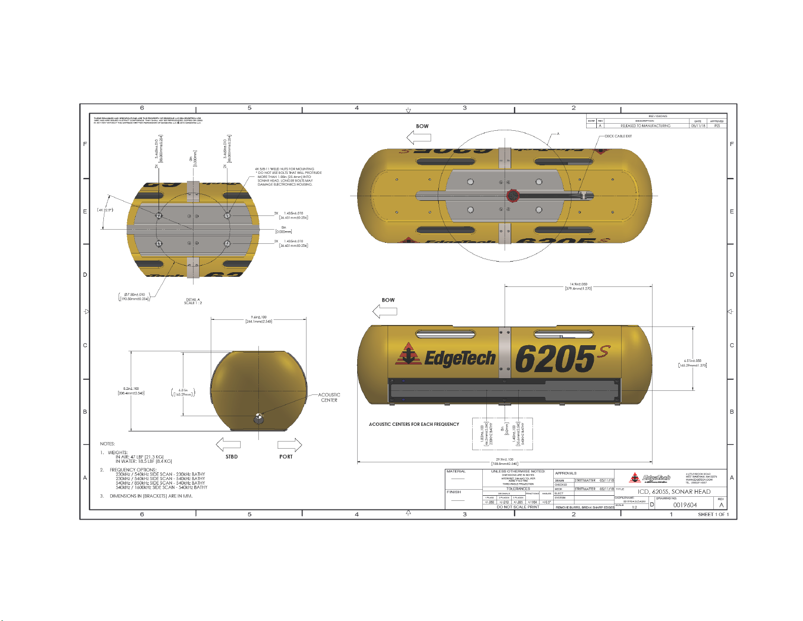
Figure 2-5: Acoustic Center Location in X, Y, and Z and Bolt Pattern of Standard 6205s – 0019604 ...... 2-10
Figure 2-6: Acoustic Center Location in X, Y, and Z Dimensions and Bolt Pattern with Adaptor Flange –
0021206 ................................................................................................................................................... 2-11
Figure 3-1: Rack Mount Topside ................................................................................................................ 3-5
Figure 3-2: 6205s-P Portable Topside ........................................................................................................ 3-6
Figure 3-3: 6205s-P Portable Topside Interface Box, Side View ................................................................ 3-7
Figure 3-4: 6205s Exploded View ............................................................................................................... 3-9
Figure 3-5: 6205s Exploded View with Adaptor Flange ........................................................................... 3-10
Figure 3-6: 6205s Transducer................................................................................................................... 3-11
Figure 3-7: 6205s Array Color Codes Diagram ......................................................................................... 3-12
Figure 3-8: 6205s Wiring Diagram – 0019627 ......................................................................................... 3-13
Figure 4-1: 6205s-R Rack Mount Topside Interface Connections .............................................................. 4-3
Figure 4-2: Sonar Data Flow ....................................................................................................................... 4-5
Figure 4-3: Chevron Pattern Noise in a Cropped Portion of Discover Bathymetric .................................. 4-7
Figure 5-1: 6205s Deployment, Option 1 – Over-the-Bow ........................................................................ 5-2
Figure 5-2: 6205s Deployment, Option 2 – Over-the-Side ........................................................................ 5-3
Figure 5-3: Unit on Stable Platform ........................................................................................................... 5-6
Figure 5-4: Removing the Cap Screws........................................................................................................ 5-6
Figure 5-5: Top Housing and Deck Cable Removed ................................................................................... 5-7
Figure 5-6: Remove the Center Bracket ..................................................................................................... 5-7
Figure 5-7: Remove the Portion of the Shell ‘EdgeTech’ and the Logo ..................................................... 5-8
Figure 5-8: The Disconnected Bathymetry and Side Scan Sonar Cables .................................................... 5-8
Figure 5-9: Remove the [6] Cap Screws ..................................................................................................... 5-9
Figure 5-10: All Cap Screws Removed ........................................................................................................ 5-9
Figure 5-11: Remove the Existing Transducer ........................................................................................... 5-9
Figure 5-12: Mount the New Transducer................................................................................................. 5-10
Figure 6-1: Manual Remote Desktop Credentials for Customer Supplied Computer ............................... 6-1
Page 15

xv
Figure 6-2: Sonar 192.9.0.101 Remote Desktop Connection Window ...................................................... 6-2
Figure 6-3: Sonar 192.9.0.101 Remote Desktop Connection Window ...................................................... 6-3
Figure 6-4: Serial Port Information Window .............................................................................................. 6-4
Figure 6-5: System Status Window ............................................................................................................ 6-5
Figure 8-1: No Sound Velocity on Port 4 .................................................................................................... 8-1
Figure 8-2: Sonar 192.9.0.101 Remote Desktop Connection Window ...................................................... 8-1
Figure 8-3: Closing the Sonar.exe Application ........................................................................................... 8-2
Figure 8-4: Connecting to COM4 using TeraTerm ..................................................................................... 8-2
Figure 8-5: COM4 Port Settings ................................................................................................................. 8-3
Figure 8-6: Scrolling SV Data in Sonar.exe ................................................................................................. 8-4
Figure 8-7: Configuration Menu ................................................................................................................. 8-5
Figure 8-8: Auxiliary Sensors ...................................................................................................................... 8-5
Figure 8-9: Sonar Control Tab .................................................................................................................... 8-6
Figure 8-10: SonarSeral.ini ......................................................................................................................... 8-7
Figure A-1: Sonar Remote Desktop Application, Main Screen .................................................................. A-2
Figure A-2: Sonar Remote Desktop, Shortcut to EdgeTech Folder ............................................................ A-2
Figure A-3: Finding the SonarSerial.ini File ................................................................................................ A-2
Figure A-4: SonarSerial.ini File ................................................................................................................... A-3
Figure A-5: Diagnostic Window, Reporting Ports Inactive Error ................................................................ A-3
Figure A-6: Rebooting Sonar from the Main Screen .................................................................................. A-4
Figure A-7: Checking Serial Port Information ............................................................................................ A-5
Figure A-8: Checking Sensor Status............................................................................................................ A-5
Figure A-9: Closing the System Status Window ......................................................................................... A-6
Figure A-10: SonarSerial.ini File ................................................................................................................. A-7
Figure A-11: Checking Sensors’ Usages ...................................................................................................... A-8
Figure A-12: All Sensors Set ....................................................................................................................... A-9
Figure A-13: Checking all COM Ports ....................................................................................................... A-11
Figure A-14: UDP Configuration Example ................................................................................................ A-12
Figure A-15: POSMV UDP Configuration .................................................................................................. A-13
Figure A-16: SonarConfig.ini Example ...................................................................................................... A-14
Figure A-17: TimeSyncSoruce Keyword Adjustments .............................................................................. A-14
Page 16

xvi
LIST OF TABLES
Table 3-1: Physical Specifications .............................................................................................................. 3-1
Table 3-2: Acoustic Specifications .............................................................................................................. 3-2
Table 3-3: Power Requirements ................................................................................................................ 3-2
Table 3-4: Environmental Specifications .................................................................................................... 3-3
Table 3-5: 6205s Topside Interface Specifications ..................................................................................... 3-3
Page 17

1-1
SECTION 1: OVERVIEW
The EdgeTech 6205s is a fully integrated Swath Bathymetry and Dual Frequency Side Scan Sonar System
that uses multiple receive elements, and one discrete transmit element, to produces real time, high
resolution, side scan imagery, and three-dimensional maps of the seafloor. The 6205s overcomes the
limitations of Multi Beam Echo Sounders (MBES) and Interferometric systems in shallow water by using
EdgeTech’s unique Multi-Phase Echo Sounder (MPES) technology. This Hybrid approach combines both
Beamforming and Phase Discrimination techniques to determine each sounding along the seafloor. With
the integration of EdgeTech’s Full Spectrum® CHIRP technology, the 6205s exceeds IHO SP-44, NOAA, and
USACE specifications for Feature Detection and Bathymetric Point Data Uncertainty.
EdgeTech’s MPES technology enables the 6205s to produce wider and cleaner swath (over 200º) than
current technologies, resulting in superior coverage enabling faster and safer survey completion. At the
same time, the 6205s rejects multipath effects, reverberation, and acoustic noise commonly encountered
in shallow water environments.
The 6205s provides Dual Frequency Side Scan Sonar, operating at 230/550 kHz, 550/850kHz or 550/1600
kHz, while the Side Scan imagery is collected simultaneously on both frequencies. The Bathymetry
operates at either 230kHz or 550kHz.
Additionally, EdgeTech’s latest 2205 Electronics and Modular Arrays are utilized in the 6205s, resulting in
an extremely lightweight design, which is required for shallow water applications and vessels of
opportunity. The 2205 electronics and arrays are mounted onto a streamline body that is deployed overthe-bow or side of a survey vessel. Sonar data is transferred from the transceiver to the processing unit
on board via an Ethernet network interface.
The standard configuration for the 6205s includes an integrated Sound Velocity Sensor, and interfaces to
most Third-Party acquisition and processing software packages, and to standard DGPS/RTK systems,
Altimeters, GPS, MRU, SVP, Gyros, and INS—altogether offering a powerful and versatile acquisition
system that is suitable for many different applications.
The 6205s has a variety of features, including:
• Next generation MPES technology
• Unrivaled Swath coverage in shallow water, when compared to other single head systems
• Swath sectors of up to 200°
• Co-registered Dual Frequency Side Scan and Single Frequency Bathymetry
• Superior multipath rejection
• IHO SP-44 Special Order compliant
• Equidistant and Equiangle output options
• Comes with EdgeTech’s Discover Bathymetric Sonar Control Software
• Motion tolerant Side Scan
• Universal MRU Mounting Plate
• Field swappable Transducers (Bathymetric Electronics can swap between 230khz or 520khz)
Page 18

SECTION 2: SYSTEM DESCRIPTION 1-2
1.1 Applications
The 6205s next generation Swath Bathymetry & Side Scan Sonar has many potential applications, a few
of which include:
• Shallow Water Hydrographic Surveys
• Benthic Habitat Mapping
• Nautical Charting
• Military Rapid Environmental Assessments (REA)
• Route Surveys
• Dredging Operations
• Marine Debris Search
• Port & Harbor Security
1.2 Options
The 6205s is available in several standard frequency configurations:
• 230 / 550 kHz Dual Frequency Side Scan with 230 kHz Bathymetry Data
• 230 / 550 kHz Dual Frequency Side Scan with 550 kHz Bathymetry Data
• 550 / 850 kHz Dual Frequency Side Scan with 550 kHz Bathymetry Data
• 550 / 1600 kHz Dual Frequency Side Scan with 550 kHz Bathymetry Data
The modular design of the 6205s allows for multi-frequency bathymetry options in a single sonar head.
The field exchangeable array capability allows both shallow and deep-water operations but is only
available with 230 / 550 kHz Side Scan systems. The difference between the different frequency arrays is
identified by color. Refer to F
IGURE 3-9 for frequency differentiations by color.
1.3 Main System Components
The following components come standard with the 6205s System:
• 6205
• D
• S
• Large Pelican Hardigg™ Shipping Case
• 6205
• DISCOVER BATHYMETRIC Acquisition Software
S SWATH BATHYMETRY AND SIDE SCAN SONAR HEAD
ECK CABLE 20m (65ft)
OUND VELOCITY SENSOR (SVS) [Mounted to Connector Endcap]
S-R RACK MOUNT INTERFACE BOX
• 6205s Tool Kit
Page 19
1-3
1.4 DISCOVER Software
EdgeTech’s DISCOVER Bathymetric Software Acquisition package provides a way to control, store, and
display the Bathymetry and Dual Frequency Side Scan Sonar data. For more information on the DISCOVER
BATHYMETRIC software, refer to its manual (0014878).
1.4.1 Third-Party Software
EdgeTech has approved a small number of Third-Party Topsides for acquisition and processing of
Bathymetry and Side Scan data. Currently, Hypack, SonarWiz, and QINSy software packages have been
approved, but work continues to expand the number of topsides. CARIS HIPS/SIPS supports our native JSF
files for post processing.
For questions on Third-Party Interfacing with DISCOVER Bathymetry, refer to T
Contact
EDGETECH CUSTOMER SERVICE for updates.
HIRD PARTY SOFTWARE.
1.5 Optional Equipment
• ARRAYS FOR FIELD EXCHANGEABLE FREQUENCY OPERATIONS
• 6205
• Adaptor Flange
• Spares Kit
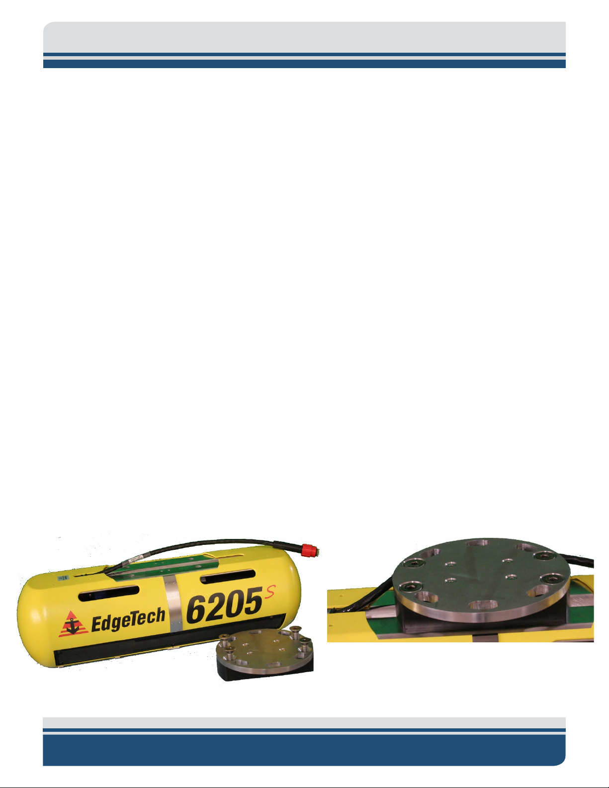
1.5.1 Adaptor Flange
The Adaptor Flange mounts to the existing Mounting Plate and is designed for static pole-mounting
operations. The Adaptor Flange is available if the standard 6205s hole pattern will not mate to the
customer’s available static pole-mount. The Adaptor Flange is attached to the M
F
IGURE 2-2 for visual depiction of the Adaptor Flange.
Refer to
S-P PORTABLE TOPSIDE WITH LAPTOP
OUNTING PLATE. Refer to
FIGURE 3-9 and FIGURE 3-10 for a comparison of bolt patterns.
Figure 1-1: The 6205s and the Optional Adaptor Flange
Page 20

SECTION 2: SYSTEM DESCRIPTION 2-4
SECTION 2: SYSTEM DESCRIPTION
The complete 6205s system consists of a Swath Bathymetry and Side Scan Sonar Head and a Topside
Interface Box. This section describes the 6205s System main components and lists its specifications.
2.1 The 6205s Sonar Head
The 6205s Swath Bathymetry and Side Scan Sonar Head is available in a variety of frequency options:
• 230 / 550 kHz Dual Frequency Side Scan with 230 kHz Bathymetry Data
• 230 / 550 kHz Dual Frequency Side Scan with 550 kHz Bathymetry Data
• 550 / 850 kHz Dual Frequency Side Scan with 550 kHz Bathymetry Data
• 550 / 1600 kHz Dual Frequency Side Scan with 550 kHz Bathymetry Data
The frequency sets listed above were chosen to provide optimum results for any given water depth up to
200m (660ft) below the transducer. The 6205s is for water depths between 5m – 50m (15ft – 164ft).
Optimal Frequency depends on survey requirements.
To mitigate frequency tradeoffs, EdgeTech has designed the 6205s Sonar Head with Field Exchangeable
Arrays whereby the Bathymetry frequency can be switched from the low frequency channel to the high
frequency channel or vice versa. However, this feature only exists on the 230 kHz/550 kHz models.
The 6205s Swath Bathymetry and Side Scan Sonar Head comes standard with a Sonar Processor, Port and
Starboard Sonar Arrays, a Sound Velocity Sensor (SVS), and Housing. These components are demonstrated
IGURE 2-1.
in F
Page 21
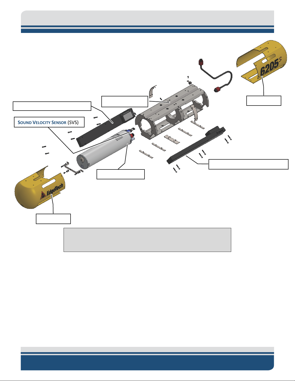
HOUSING
M
OUNTING PLATE
SONAR PROCESSOR
SOUND VELOCITY SENSOR (SVS)
SONAR ARRAYS (PORT and STBD)
HOUSING
SONAR ARRAYS (PORT and STBD)
2-5
NOTE: The terms used in Figure 2-1 are referenced throughout this
manual.
Figure 2-1: 6205s Sonar Head Components
Page 22
SECTION 2: SYSTEM DESCRIPTION 2-6
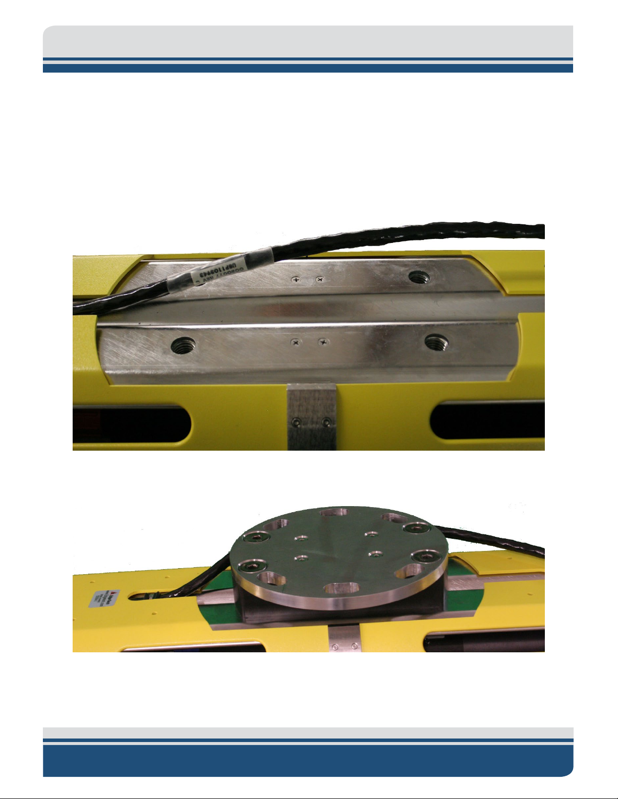
2.1.1 Mounting Plate
The 6205s Mounting Plate is made of stainless steel and was designed with a variable bolt pattern to
secure the system to several different deployment mechanisms, thereby cutting back on installation and
mobilization time. The variable bolt pattern is shown in F
EdgeTech advises mounting the 6205s Sonar Head to the bow of a survey vessel. By placing the system at
the bow, the sonar should be far enough away from most interference, such as hull echoes, propeller
noise, and wake.
IGURE 2-3.
Refer to
Figure 2-2: The Mounting Plate
FIGURE 2-5 and FIGURE 2-6 for a comparison of bolt patterns.
Figure 2-3: The Optional Adaptor Flange Installed onto the Mounting Plate
Page 23

2-7
2.1.2 Housing
The 6205s shells are thermoformed Polycarbonate (PC). The Internal Frame is made of electropolished
316 stainless-steel and Acetal Homopolymer (Delrin). The housing supplies a streamline body for efficient
underwater maneuvers rated up to 12 knots, while protecting the SVS, arrays, and deck cable connections.
NOTE: Although the 6205s can handle transit up to 12 knots, survey
speeds should be constrained to 4-5 knots or less. However, EdgeTech
recommends removing the Sonar Head from the water during transit
above 7-8 knots.
2.1.3 Sonar Processor
The 6205s Sonar Processor has a built-in Windows 7 Embedded PC. The main firmware installed on the
embedded PC is called Sonar.exe, which controls the sonar’s hardware and performs specific functions,
such as signal processing and time synchronization of the acquired data.
2.1.4 Sound Velocity Sensor
The 6205s Sonar Head has a flooded section that is used to house an AML Sound Velocity Sensor (SVS),
which provides a response time of 47 μs, a resolution of 0.001 m/s, and a theoretical accuracy of ±0.025
m/s. A closer look at the SVS is presented in F
EdgeTech recommends collecting a sound velocity profile, especially in the area where you collect test
data. The water being operated in likely does not have a uniform sound velocity, and depending on how
drastic the profile is, a depth error as large as 1.6 m has been observed.
IGURE 2-4.
Page 24

SECTION 2: SYSTEM DESCRIPTION 2-8
Figure 2-4: 6205s Electronics Housing and Arrays Installed
Page 25

2-9
2.1.5 Sonar Arrays
The 6205s provides single frequency Bathymetry and Simultaneous Dual Frequency Side Scan Sonar.
The Side Scan Sonar operates at 230/550 kHz, 540/850, or 550/1600 kHz and collects simultaneously on
both frequency channels. Bathymetry is obtained on either the 230 kHz or the 550 kHz. The 6205s utilizes
two arrays (port and starboard) to map the seafloor much like a Dual Head Multibeam System. Each 6205s
Array is constructed using 10 independent longitudinal PZT elements and two multi-segment PZT strings.
The two multi-element strings (one per Side Scan Frequency) are used for the transmit function and as a
full resolution side scan receiver. The remaining 10 elements make up approximately half-wavelength
spaced array of sensors for its bathymetry receiver.
2.1.6 Acoustic Center
The individual Acoustic Centers of each Array (port and starboard) converge at a single point along the
centerline of the 6205s Sonar Head. Therefore, when entering sonar head offsets into the Third-Party
acquisition and processing software, the port and starboard array offsets (or sometimes referred to as
Sonar Head 1 and Sonar Head 2, respectively) are identical in all dimensions.
The EdgeTech convention for X, Y, and Z is:
• X is positive to starboard
• Y is positive forward
• Z is positive down
Remember that the individual Acoustic Centers for both port and starboard converge on the centerline
(or X = 0).
NOTE: The Acoustic Center along the Y axis is different for the 230kHz
model than the 550kHz model.
For a larger representation of FIGURE 2-5 and FIGURE 2-6
Page 26
SECTION 2: SYSTEM DESCRIPTION 2-10
Figure 2-5: Acoustic Center Location in X, Y, and Z and Bolt Pattern of Standard 6205s – 0019604
Page 27

2-11
Figure 2-6: Acoustic Center Location in X, Y, and Z Dimensions and Bolt Pattern with Adaptor Flange – 0021206
Page 28

SECTION 3: SPECIFICATIONS
Size
76.2 L x 21.1 W x 27.9 H cm
(30 L x 8.3 W x 11 H in)
Weight
(W/o Adapter Flange): 21.3 kg (47 lbs)
(W/ Adapter Flange): 25.9 kg (57.1 lbs)
Construction
Polycarbonate / 316 Stainless Steel Frame
Color
Blue Angels Yellow
Sealing
O-Ring Seal with Purge Valve
Center Frequency
230/520 kHz
520/1610 kHz
Range (per Side)
225/125 m (738/410 ft)
125/35m (410/115 ft)
Range Resolution
30/15 mm (1.18/0.4 in)
15/6 mm (0.4/0.2 in)
Beam Width Along
Track
0.64°/0.47° (2-way)
0.47°/0.2° (2-way)
Depression Angle
35°
35°
Center Frequency
230 kHz/520kHz
520 kHz
Maximum Swath
350 m (1148 ft)
150 m (492 ft)
Beam Width Along
Track
0.64°/0.47°
0.47°
Ping Repetition
15 m (16 ft) = 50 Hz
200 m (656 ft) = 4 Hz
5 m (16 ft) = 150 Hz
150 m (492 ft) = 5 Hz
Sonar Frequency
230 kHz
550 kHz
beamwidth at nadir
This section details the System Specifications of the 6205.
3.1 Physical Specifications
PHYSICAL
Table 3-1: Physical Specifications
3-1
3.2 Acoustic Specifications
SONAR HEAD
MODEL
SIDE SCAN SONAR
SWATH BATHYMETRY
Rate
(Both Sides
Simultaneously)
230/550 KHZ SS – 230/550 BATHY 550/1600 SS - 550 KHZ BATHY
25 m (82 ft) = 30 Hz
50 m (164 ft) =15Hz
100 m (328 ft) = 8 Hz
25 m (82 ft) = 30 Hz
50 m (164 ft) = 15 Hz
100 m (328 ft) = 8 Hz
BATHYMETRY
Beamwidths
Across track resolution
expressed as a
1° x 0.7° 1° x 0.5°
Page 29

SECTION 3: SPECIFICATIONS 3-2
reverberation, sea noise)
environmental conditions
Max Swath Sector
200°
Soundings
Patterns
Frequency
230 kHz
550 kHz
850 kHz
1600 kHz
way)
Range Resolution
30 mm
10 mm
9 mm
6 mm
reverberation, sea noise)
Pulse Modulation
CW & FM CHIRP
Construction
Polycarbonate / 316 Stainless Steel Frame
Dimensions
208 x 244 x 759 mm (8.1 x 9.6 x 29.8 in)
Length
Depth Rating
50 m Weight (In Air)
19.9 kg (44 lbs)
Input Voltage
48-60 VDC
(Typical /Max)
Data Products
Bathymetry, Backscatter and Side Scan Imagery, and Real Time Uncertainties
DC Input Range
36-60 VDC (48 VDC Nominal)
36-60 VDC (48 VDC Nominal)
100 m
400 m
50 m
200 m
Max Sounding
Depth
Dependent on
environmental conditions
(absorption,
Max Swath Width
Assumes a flat seafloor
and dependent on
Max Number of
Sounding
800
Equidistant and Equiangular
SIDE SCAN SONAR IMAGERY
Horizontal
Beamwidth (2-
Max Range
Dependent on
environmental conditions
(absorption,
SYSTEM
Deck Cable
0.54°
250 m
20m (Standard)
0.36°
0.29° 0.20°
150 m
75 m
35 m
Power
55W / 70W
Table 3-2: Acoustic Specifications
3.3 Power Requirements
POWER REQUIREMENTS
Table 3-3: Power Requirements
Page 30

3.4 Environmental Specifications
Size
L: 48.3cm x W: 52.1cm x H: 8.9cm
(L: 19 x W: 20.5 x H: 3.5 )
L: 49.5cm x W: 38.1cm x H: 19.1cm
(L: 19.5” x W: 15” x H: 7.5”)
Weight
5.4 kg (12 lbs)
13.6 kg (30 lbs)
Construction
Aluminum
Polyethylene/Polyurethane
Interfaces
(1) 1 PPS via BNC
(3) Serial RS-232 Ports
(1) 1 PPS via BNC
(3) Serial RS-232 Ports
POWER REQUIREMENTS
Input Power Supply
115/230 VAC Auto-Sensing
115/230 VAC Auto-Sensing
Output Power Supply
60VDC
48VDC
Current Draw
1.40A
1.40A
Operating Temperature
0°C to 40°C (32°F to 104°F)
0°C to 40°C (32°F to 104°F)
Storage Temperature
-20°C to 60°C (-4°F to 140°F)
-20°C to 60°C (-4°F to 140°F)
Relative Humidity
Operating 0 to 80%,
Non-Operating 0 to 100%
Operating 0 to 80%,
Non-Operating 0 to 100%
ENVIRONMENT
Table 3-4: Environmental Specifications
3.5 Topside Specifications
Detailed specifications for 6205s Topside Interfaces and Sonar Heads are provided in
INTERFACE MODEL 6205S – RACK MOUNT 6205S - PORTABLE
PHYSICALS
3-3
(1) Trigger In via BNC
(4) 100 BaseT Ethernet Ports
Table 3-5: 6205s Topside Interface Specifications
(1) Trigger In via BNC
(3) 100 BaseT Ethernet Ports
Page 31

SECTION 3: SPECIFICATIONS 3-4
3.6 The 6205s Topside Sonar Interface Box
The 6205s Topside Sonar Interface Box has two purposes:
1. To provide power to the Sonar Head
2. To provide a direct link between Sonar Head, any supporting sensors, and Topside Computer.
The Topside Sonar Interface Box delivers power to the system and transmits/receives data via the
provided 20m (65ft) Deck Cable and a SubConn 16 pin wet mate connector. The Topside Sonar Interface
Box supplies (3) RS232 serial ports to intake Navigation, Heading, and Attitude Data from the supporting
sensors and an Ethernet port to communicate with the Topside Computer.
The first two RS232 serial ports are configured for high speed and high accuracy, while the third RS232
serial port is configured for standard serial connections. Typical latencies for the high speed/high accuracy
ports are less than 100us, whereas the standard serial port may have up to 100ms. The high-speed ports
are unidirectional, data cannot be transmitted from the 6205s to an external device. All three com ports
are isolated via a proprietary Signal Conditioning / Isolator board. This ensures noise generated or carried
by grounds on the survey vessel do not generate artifacts in the Side Scan and Bathymetry data sets.
The 6205s can receive data from supporting sensors via the Ethernet connection utilizing UDP. Refer to
SUB-SECTION B.4 for more information on configuring 6205s for UDP data transfer.
This Topside Sonar Interface Box comes in two forms:
6205S-R RACK MOUNT TOPSIDE INTERFACE for use with a Customer-supplied computer.
1.
2. 6205S-P PORTABLE TOPSIDE INTERFACE for use with: Customer-supplied computer or purchased
EdgeTech-supplied fully configured Laptop.
Both the 6205s-Portable and 6205s-Rackmount come with a USB which contains manuals and Discover
Bathymetry. Optional laptops come preloaded with EdgeTech’s DISCOVER BATHYMETRIC Acquisition
Software and all Manuals. DISCOVER BATHYMETRIC can also be downloaded from the EdgeTech FTP site.
Contact E
DGETECH CUSTOMER SERVICE for FTP credentials.
Page 32

3-5
3.6.1 6205s-R Rack Mount Topside Interface
The 6205s-R Rack Mount Topside Sonar Interface Box was designed to slide into a 19-in Rack Mount
Optima Case. It provides three input/output serial ports, four Ethernet ports, AC power input, On/Off
switch, and two BNC connectors that supply an input trigger and 1PPS sync. The three input serial ports
act as a dry connection to the sonar head for all ancillary information (i.e. position, attitude, time, etc.),
while the four Ethernet ports provide 100Mbps connection from the sonar head to the topside computer.
These interfaces are shown in F
IGURE 3-1.
Figure 3-1: Rack Mount Topside
The Rack Mount Topside Sonar Interface Box option does not come with a topside computer, this must
be supplied by the customer. See the minimum requirements provided in sub-section 3.6.3.
If the 6205s-R Rack Mount Topside Interface Box does not turn on, check the on/off switch on the back
panel. It is located next to the power plug.
Page 33

SECTION 3: SPECIFICATIONS 3-6
3.6.2 6205s-P Portable Topside Interface
The 6205s-P Portable Topside Interface is a splash proof design of the 6205s-R Rack Mount Interface box.
It offers all the same connections to the 6205s Sonar Head for the supporting sensors (i.e. GPS, MRU, etc.)
through a series of break out cables. The Portable Topside has an option for a laptop. The laptop is a highperformance PC, running Windows 10 operating system. It also has a Quad Core processor (8 cores) and
comes with a 1TB hard drive.
CAUTION!
The laptop’s performance changes when running on battery power so
ensure the laptop is plugged in when operating the Sonar and acquiring
real time Bathymetry and Side Scan Data.
Figure 3-2: 6205s-P Portable Topside
Page 34

Figure 3-3: 6205s-P Portable Topside Interface Box, Side View
3-7
3.6.3 Topside Computer Requirements Specifications
The topside computer must be able to run EdgeTech’s DISCOVER BATHYMETRIC Acquisition Software and
any additional Third-Party software. To do so, it must include the following minimum requirements:
• Windows 10 Professional Operating System
• Quad-Core Intel Core i7-4900MQ @ 2.8GHz Processor or similar
• 8 GB of Memory (RAM)
• 500GB Hard Drive
• 3 USB Ports
• 1 Ethernet Port
• 1 GB Graphics Card
The 6205s-Portable has an optional Ruggedized GETAC Laptop, preloaded with EdgeTech’s DISCOVER
Bathymetric Software and all supporting software. The laptop has the specifications below:
• Windows 10 Professional Operating System
• Intel® Core™ i7-8650U vPro 1.9GHz processor with Turbo Boost Technology
• 8 GB of Memory (RAM)
• 1TB Hard Drive
• Intel UHD Graphics 620
• NVIDIA Quadro M2000M (4GB GDDR5)
• 3 USB 3.0 (9-pin)
• 1 USB 2.0 (4-pin)
• 1 Ethernet RJ45 Port
• 1 Mini Display Port1 HDMI Port
Page 35

SECTION 3: SPECIFICATIONS 3-8
NOTE: The Topside laptop may look and operate like a general-purpose
PC, however, installing additional software outside the provided
EdgeTech and Bathymetric Third-Party Software is NOT recommended.
Installing software other than those supplied can have undesirable
effects, such as poor and/or slow performance when acquiring
Bathymetry and dual frequency Side Scan data. A list of approved ThirdParty packages is provided in THIRD PARTY SOFTWARE.
3.7 Deck Cable
The Deck cable is a 20 meter (65ft) underwater, high speed network data and power cable. Deck cable
includes Cat 5e 4-pair stranded conductors that meets or exceeds TIA 568-B and is suitable for 10Base-T
and 100Base-T. Deck cable is terminated with a Subconn 16 pin wet mate connector on both ends, has a
breaking strength of 545 kg (1200lbs), and provides power and telemetry to 6205s Sonar Head.
CAUTION! DO NOT use Deck Cables for towing.
3.8 Mechanical Drawings
This section contains supporting drawings for the 6205s Swath Bathymetry and Dual Frequency Side Scan
Sonar System:
Page 36

3-9
Figure 3-4: 6205s Exploded View
Page 37

SECTION 3: SPECIFICATIONS 3-10
Figure 3-5: 6205s Exploded View with Adaptor Flange
Page 38

3-11
Figure 3-6: 6205s Transducer
Page 39

SECTION 3: SPECIFICATIONS 3-12
COLOR CODES
Color Code:
Green = 550/1600SS – 550 Bathy
The 6205s Arrays have been color coded based on their operating frequency. The color code is shown and described below:
Blue = 230/550SS– 230 Bathy
Red = 230/550SS – 550 Bathy
Yellow = 550/850SS – 550 Bathy
Figure 3-7: 6205s Array Color Codes Diagram
Page 40

3-13
Figure 3-8: 6205s Wiring Diagram – 0019627
Page 41

4-1
SECTION 4: CONNECTIONS AND FORMATS
The 6205s System relies on specific data formats and connections to produce its high-quality images and
measurements. This section describes these data formats and connections along with providing diagrams
to help the user better understand the hardware and data flow within the system.
4.1 Data Formats
In order to collect valid survey data the following is required to support the survey operations and correct
processing of the 6205s Bathymetry and Dual Frequency Side Scan echo data:
a. GPS Position in NMEA format, latitude and longitude; minimum of 5Hz
b. Heading data in NMEA format or EM1000 binary format; minimum of 20Hz
c. Attitude or Roll, Pitch, and Heave data in TSS1 or EM1000 binary format; minimum of 20Hz
d. Time sync data in NMEA format; minimum of 1Hz
These data may be supplied by 1, 2, or 3 individual sources, and are listed below in order of priority.
a. Position Data – this may be supplied via any of the following NMEA type sentences/messages:
i. $xxGGA
ii. $xxGLL
iii. $xxRMC
$xxGGK ** (Applanix PosMV Format) ** = Non-NMEA standard sentences
iv. $PTNL, GGK, … ** (Trimble Format)
b. Heading Data – this may be input via:
i. NMEA, $xxHDT sentence, OR
ii. EM1000 binary format along with attitude data
c. Attitude (Roll, Pitch, and Heave) Data – this may be input via:
i. TSS1 format, OR
ii. EM1000 binary format
d. Time Input - supported sentences are in order of priority/use
i. $xxZDA
ii. $xxRMC
iii. $xxGGK (derived from data in item a. above)
iv. $xxGGA (only supports time, no date field)
v. $xxGLL (only supports time, no date field)
Page 42

SECTION 4: CONNECTIONS AND FORMATS 4-2
NOTE: The prefix “$xx” represents proprietary NMEA message prefix for
a specific manufacturer. $GPGGA, $GPZDA, etc. are example NMEA
output sentences for a Hemisphere GPS.
We recommend you also supply the system with a source of Speed Over
Ground in NMEA format (i.e. VTG, minimum of 1Hz) so that the system
can correctly compute Along-Track Distance between each ping and
display it in DISCOVER BATHYMETRIC Software.
Messages can be sent over ethernet connection via UDP functionality.
4.2 System Connections and Data Flow
The following sub-sections describe the connections and data flow for the 6205s System.
4.2.1 Ethernet LAN Connections
The Ethernet LAN connection from the Sonar Head to the 6205s Topside Interface is made using a physical
wired connection via a 40inch extension and the standard 20m (65 ft) Deck Cable. The 6205s Sonar
Interface then connects to a Topside Computer via a standard RJ-45 Ethernet plug. The correct IP
addresses for the sonar head and topside PC are listed below. The 6205s Sonar Interface then connects
to a Topside Computer via a standard RJ-45 Ethernet plug. The correct IP addresses for the sonar head
and topside PC are listed below.
• Sonar Head IP Address = 192.9.0.101
• Topside PC IP Address = 192.9.0.99
NOTE: Factory defaults for the 6205s Sonar head IP address is
192.9.0.101 and should not be changed for any reason. The supplied
laptop with the 6205s-P portable topside interface will also be
preconfigured to 192.9.0.99 on delivery from the factory. Only when the
customer supplies their own topside computer that the IP address needs
to be set to the address above.
Page 43

4-3
Heading,
Position, Time
Attitude, Heading,
Position, Time
Not Used
Attitude, Heading,
Not Used
6205s Sonar Head
Example 1
Attitude
Not Used
Example 2
Example 3
Power
115/220 VAC
Not Used
Not Used
Topside Computer
4.2.2 Serial Port Connections
There are three RS-232 serial ports provided on the 6205s Sonar Interface box. COM1 and COM2 have
been configured for high speed and high accuracy). COM3 is configured for standard RS-232 serial
connections. Typical latencies for the high speed/high accuracy ports are less than 100us, whereas the
standard serial port has up to 100ms.
These serial ports are provided to intake the navigation, heading, and attitude (roll, pitch, and heave) data
from the supporting sensors. Refer to CONFIGURING
COM PORTS to configure the COM ports.
If the Rack Mount topside is being utilized, it can serve as a splitter for serial data. The output ports pair
with the serial ports located directly above them. These ports are unidirectional.
4.2.3 Hardware Connectivity
FIGURE 3-1 is a block diagram that illustrates interconnections between the 6205s Swath Bathymetry and
Dual Frequency Side Scan Sonar Head, the 6205s-R Rack Mount Topside Interface, and all supporting
sensors. This illustration gives examples of three possible sensor configurations that are explained below.
IP Address 192.9.0.99
IP Address: 192.9.0.101
Position, Time
Figure 4-1: 6205s-R Rack Mount Topside Interface Connections
The 6205s-P Portable Topside Interface connections are similar and is presented in F
IGURE 3-10.
IGURE 5-1, the 6205s Sonar Interface connects to Sonar Head via Deck Cable. Time, navigation, heading,
In F
roll, pitch, and heave data from supporting sensors via COM ports 1, 2, and/or 3, are inputted at Sonar
Interface, passed through the Deck Cable, and logged by Sonar Processor in Sonar Head.
Page 44

SECTION 4: CONNECTIONS AND FORMATS 4-4
These data are transmitted (along with the raw side scan data) with a common timestamp up the Deck
Cable to the 6205s Sonar Interface and are then passed to the Topside Computer through an Ethernet
cable and via the 100Mbps link on Ethernet Port 1 (IP Address: 192.9.0.99).
The Topside Computer then processes these data using the DISCOVER BATHYMETRIC software to send
amplitude, angle and range data to the 3rd party software for logging and post processing. This process is
explained in further details in the following section. The 3rd party software and DISCOVER BATHYMETRIC
processors may all run on the same computer.
4.2.3.1 Serial Port Configuration Examples
The example in FIGURE 4-1 depicts a sensor interfacing to the 6205s Sonar Interface that provides time,
navigation (latitude/longitude), heading, roll, pitch, and heave data over one serial connection—such as
a NovaTel ProPak 6 or Applanix PosMV. As depicted in F
The second example shows the most common interfacing scenario, a GPS that provides navigation and
heading data, accompanied by a motion sensor for attitude measurements.
The COM ports should be assigned as such:
IGURE 4-1, the sensor is connected to COM1.
• COM1 = MRU (Roll, Pitch, Heave)
• COM2 = GPS (Navigation and Heading)
These assignments may be interchanged between COM1 and COM2 because both ports have been
configured for high speed and high accuracy. COM3 should not be used in this scenario.
The third and last example portrays a situation where the GPS does not provide heading data. In this case,
three sensors are required: a GPS for navigation (latitude/longitude), a Gyro for heading, and a motion
sensor for roll, pitch, and heave measurements.
Therefore, all three COM ports should be used and assigned as follows:
• COM1 = MRU (Roll, Pitch, Heave)
• COM2 = Gyro (Heading)
• COM3 = GPS (latitude/longitude/time)
The sensors allocated to COM1 and COM2 may be interchanged for the same reason stated in the second
example. GPS data, or latitude and longitude data, must be allotted to COM3 because position can
tolerate a 100ms latency, whereas attitude and heading are crucial to correcting wide swath of data.
NOTE: To configure the serial ports according to the examples given
above, see CONFIGURING COM PORTS.
Page 45

4-5
4.2.4 Sonar Data Flow
The DISCOVER BATHYMETRIC software acquisition package provides a way to control, store, and display
the bathymetry and side scan sonar data. DISCOVER BATHYMETRIC contains two processors: one to
process the bathymetry solutions, called the Bathymetric Processor, and the second to process and
display the dual frequency side scan data. To illustrate the data flow between DISCOVER, the Bathymetric
Processor, and any Third-Party software, the block diagram in F
NOTE: The 6205s Sonar Interface Box flow chart can be used in either the
6205s-R Rack Mount Interface Box or 6205s-P Portable Interface Box.
IGURE 4-2 is used.
Figure 4-2: Sonar Data Flow
Page 46

SECTION 4: CONNECTIONS AND FORMATS 4-6
The flow chart in
FIGURE 4-2 demonstrates the following:
1. The auxiliary sensors provide time, heading, position (latitude/longitude), and motion (roll, pitch,
and heave) data to the 6205s Sonar Interface Box via the provided RS-232 serial ports or UDP
connections over the ethernet link.
2. These auxiliary data are then relayed to the 6205s Sonar Head via the Deck Cable.
3. Here, the auxiliary data are combined with the raw sonar data and instantaneous sound velocity
(SV) measurements, where they are time stamped with a common value, and then sent back to
the 6205s Sonar Interface.
4. DISCOVER BATHYMETRIC takes in the raw sonar data and sends it to the Bathymetric Processor.
5. The Bathymetric Processor processes the raw sonar data to produce uncorrected range and angle
data, and then transmits this back to DISCOVER BATHYMETRIC, where it is packaged with the
auxiliary and dual frequency side scan data. At this point, each ping is represented by a complete
data package containing all sonar and auxiliary data.
NOTE: Once the data is passed back to DISCOVER BATHYMETRIC these
data are shown on the provided graphical displays to illustrate the
bathymetry and simultaneous dual frequency side scan data in real time.
These data may also be recorded as a *.JSF file if the user desires.
6. This complete data package (range/angle, dual frequency side scan, and all auxiliary data) is sent
to the Third-Party software.
7. The Third-Party software then logs these complete data packets to their native format. The Third-
Party software also provides graphical displays to show the bathymetry, dual frequency side scan,
and auxiliary data.
8. Finally, these three-dimensional Third-Party data files contain every piece of information to post
process the data and generate hydrographic final products.
Page 47

4-7
Chevron Pattern Noise
Chevron Pattern Noise
4.3 Topside Provided Isolation
The two most common sources of noise are Power Supplies and poor grounding on survey vessels. To
protect against the noise fluctuations on the ground line of the subsea electronics, every Topside is
shipped with EdgeTech’s proprietary Signal Conditioning and Isolation Board. This board isolates the
sensitive subsea electronics from potentially noisy grounds provided by the trigger and serial port inputs.
Noise can often be identified as repeating patterns at the edge of the usable range of data within
DISCOVER’s Waterfall Display.
Figure 4-3: Chevron Pattern Noise in a Cropped Portion of Discover Bathymetric
Page 48

5-1
SECTION 5: INSTALLATION
This section provides an overview for unpacking, inspecting, installing, and caring for the EdgeTech 6205s
Swath Bathymetry and Dual Frequency Side Scan Sonar System.
5.1 Unpacking and Inspecting
The Sonar Head is shipped in a heavy duty and reusable transport case. The Interface Box with cables,
optional Laptop, and USB are shipped in a cardboard box with appropriate packing material. All
documentation, including manuals, is provided in electronic form on the USB.
Before unpacking the System’s components, inspect the shipping containers for damage. If any damage
is found, report it to the carrier and to EdgeTech immediately. If the shipping containers appear damage
free, carefully unpack the components and inspect them.
Check the packing list and verify all the items on the list are included. If any damage is found after
unpacking the components, immediately report it to the carrier and to EdgeTech. If any items are missing,
contact E
DGETECH CUSTOMER SERVICE. Do not install or operate any equipment that appears damaged.
Although the items shipped may vary, depending on the customer’s requirements, the standard
components for the 6205s Swath Bathymetry and Dual Frequency Side Scan Sonar system are listed in
SECTION
1: OVERVIEW.
5.2 Sonar Head Installation
Installing the 6205s System on the survey vessel is the customer’s responsibility, but it is important to
keep the following considerations in mind.
1. The Sonar Head can be mounted on the side of a vessel, but it is recommended to secure the
6205s to the bow of the boat.
2. If the customer wishes to mount the sonar off the side of their vessel, care must be taken to
ensure keel clearance.
Page 49

SECTION 5: INSTALLATION 5-2
5.2.1 Over-the-Bow Deployment
The first, and recommended option, is to mount the 6205s Sonar Head to the bow of the survey vessel.
An example of an over-the-bow deployment is depicted in the photographs in
with this type of installation, do not hesitate to contact E
DGETECH CUSTOMER SERVICE.
FIGURE 5-1. If help is needed
Figure 5-1: 6205s Deployment, Option 1 – Over-the-Bow
Page 50

5-3
5.2.2 Over-the-Side Deployment
An alternative to the bow mount is to secure the 6205s Sonar Head over the side of the survey vessel via
a pole. An example of an over-the-side deployment is illustrated in the images in F
needed with this type of installation, contact E
DGETECH CUSTOMER SERVICE.
IGURE 5-2. If help is
Figure 5-2: 6205s Deployment, Option 2 – Over-the-Side
5.3 Positioning the Topside Interface Box
The Topside Interface Box can be set up several ways, depending on the model purchased. The 6205s-R
19-in Rack Mount version should be located and set up in a dry, sheltered area on the survey vessel that
is protected from weather and water spray.
The 6205s-P portable design is a bit more versatile since it is watertight when closed (but cannot ever be
submerged) and can be set up anywhere on the survey vessel that is most convenient. Care should be
taken however, to keep the ends of the breakout cables dry.
Avoid areas of direct sunlight, especially in tropical environments, as heat build-up can occur and viewing
status indicators can become difficult. Furthermore, the location should enable direct communications
with the deck crew that is operating the survey vessel, Sonar Head, and other supporting sensors.
Page 51

SECTION 5: INSTALLATION 5-4
5.4 Topside Connections
After the Sonar Head has been installed, and the Topside Interface Box correctly placed on the survey
vessel, the supporting sensors can now be connected. To connect the supporting sensors, Sonar Head,
and Topside Interface Box:
1. Setup the MRU as described in the MRU’s user manual.
2. Position and secure the MRU to the vessel’s center of motion. If the MRU cannot be mounted in
this location, then try to mount it as close as possible to the center of motion.
3. Setup the GPS as described in the GPS’s user manual.
4. Position and secure the GPS Antennas so that they have a clear view of the sky. Also ensure that
the GPS receiver is secured in a dry, sheltered area on the survey vessel that is protected from
weather and water spray.
5. Ensure the sonar head is properly installed on the pole mount (whether at bow or vessel side).
6. Measure relative location of the MRU to the vessel’s center of motion. If the MRU was mounted
exactly at the vessel’s center of motion, these measurements would be recorded as (0,0,0).
7. Measure the location of the GPS relative to the vessel’s center of motion. Typically, the primary
antenna is used as the source of position. In this case, use the location of the primary antenna to
measure the installation offset for the GPS.
NOTE: These measurements are important and will be used later as
installation offsets in the Third-Party software. Make sure to measure
and note the exact location of the sensors to the vessel’s center of
motion. Also, remember the Z dimension is referenced to the water line.
8. Measure the location of the sonar head’s acoustic center relative to the vessel’s center of motion.
The location of the acoustic center, as shown in
9. Provide power to the 6205s Interface Box via the provided power cable.
FIGURE 2-5 and FIGURE 2-6.
10. Connect the Sonar Head to the 6205s Topside Interface box via the Subconn 16 pin connector.
Page 52

11. Connect the MRU to COM1 and the Dual Head GPS to COM2 (or vice versa).
a. A MRU is used to measure the pitch, roll, and heave of the survey vessel.
b. A dual head GPS is used to gather heading and position (latitude/longitude) data.
NOTES: If the GPS does not supply heading (i.e. single head only), then a
Gyro (or other source of heading) must be used. In the case where
another sensor is needed to provide heading, the sensors should be
connected as COM1 – MRU, COM2 – Heading, COM 3 – GPS. The low
latency ports (COM1 and COM2) must be designated to the low latency
sensor information (i.e., attitude and heading).
Refer to sub-section 3.2.2 for more information on connecting the COM
Ports. Use CONFIGURING COM PORTS to configure the COM ports for the
individual sensors.
5-5
12. Connect the 6205s Interface box to the topside computer using an Ethernet cable.
13. Turn the PC on and launch DISCOVER BATHYMETRIC Software.
14. If desired, launch any one of the supported Third-Party software packages setup the 6205s drivers,
and input the installation offsets measured in steps 6 through 8.
At this point, all equipment and software are ready for surveying.
See SECTION
5: PRINCIPLES OF OPERATION for use of the system.
5.5 Field Exchangeable Frequency Operations
The Field Swappable functionality is only possible with 230 / 550 kHz Side Scan systems.
In order to switch between different bathymetry frequencies, the 6205s Arrays must be exchanged with
the corresponding Bathymetry Array. For instance, if the Sonar Head is currently configured as a 230
kHz/550 kHz Side Scan with 230 kHz Bathymetry and the user wants to exchange the Bathymetry
frequency to the 550 kHz channel, then the following procedure should be followed.
Tools
• 1/16-inch Allen Wrench
• 3/16-inch Allen Wrench
Page 53

SECTION 5: INSTALLATION 5-6
1. Place the 6205s on a stable and level platform, such as a workbench or boat deck.
Figure 5-3: Unit on Stable Platform
2. Removing the [8] cap screws using a
1
/16” Allen key, on the right and left sides of the housing.
Figure 5-4: Removing the Cap Screws
Page 54

3. Flip the 6205s over, so the bottom of the unit is upright to expose the remaining brackets.
Figure 5-5: Top Housing and Deck Cable Removed
4. Remove the [4] screws in the widest, center bracket.
5. Then, remove the [4] remaining screws in the [2] other brackets.
5-7
Figure 5-6: Remove the Center Bracket
NOTE: You DO have to remove the shell which the black pigtail come
from. You DO NOT have the remove the front shell.
Page 55

SECTION 5: INSTALLATION 5-8
6. Slide the shell off the Housing.
Figure 5-7: Remove the Portion of the Shell ‘EdgeTech’ and the Logo
7. Unplug the Bathymetry and Side Scan Sonar Cables on the Transducer you’re replacing.
Figure 5-8: The Disconnected Bathymetry and Side Scan Sonar Cables
Page 56

8. Remove all six
1
/4” – 20 x 1.5” cap screws using the same 3/16” Allen key.
Figure 5-9: Remove the [6] Cap Screws
5-9
Figure 5-10: All Cap Screws Removed
9. To remove the Transducer, slide it away from the Housing and pull it straight out of the Frame.
Take care not to damage the Side Scan and Bathymetry Cables out of the Frame.
Figure 5-11: Remove the Existing Transducer
Page 57

SECTION 5: INSTALLATION 5-10
10. To mount the new Transducer, insert the Side Scan and Bathymetry Cables into the housing and
through the Frame.
Figure 5-12: Mount the New Transducer
11. Place the Transducer onto the Frame and align the screw holes. To keep the Transducer in place,
insert two screws on the top and bottom of opposing corners.
12. Repeat the same steps for the opposite Transducer.
CAUTION! Each array is labeled according to which side it corresponds to
so ensure the port array is installed on the port side and the starboard
array is installed on the starboard side. The sonar processor contains
calibration data that is specific to each array and these must be installed
correctly for calibration to be successful.
13. Complete the Transducer Installation by completing the steps above in reverse.
Page 58

6-1
SECTION 6: CONNECT TO SONAR
This section describes how to connect to the sonar, ensure all supporting data is present within the system
for proper operation, and correctly time sync the 6205s data. It also briefly describes the EdgeTech
DISCOVER BATHYMETRIC software. For more information, refer to the DISCOVER BATHYMETRIC Software
User Manual (0014878).
6.1 Connecting to Sonar via Remote Desktop
The user should only need to connect to the Remote Desktop Connection (Sonar.exe) and check to see
the status of the supporting data if a device is not connected properly. If this is the case, DISCOVER
BATHYMETRIC will display its diagnostic window and show which serial port is causing the error. It is not
recommended to connect to the sonar without EdgeTech support, except for the Instructions Below.
There are two ways to connect to the 6205s Sonar depending on which interface box is connected:
1. 6205
S-R 2. 6205S-P
6.1.1 Connecting with the 6205s-R
If using a customer-supplied computer with the 6205s-R (Rack Mount) Interface Box:
1. Navigate to the Remote Desktop. ‘Start’ button > All Programs > Accessories > Remote Desktop
Connection. Alternatively, click ‘Start’ button, type mstsc in Search, and hit <Enter>. The following
window will appear:
Figure 6-1: Manual Remote Desktop Credentials for Customer Supplied Computer
Page 59

SECTION 6: CONNECT TO SONAR 6-2
2. Connect to the 6205s Sonar using an IP address of 192.9.0.101 and User name of Administrator.
3. When prompted for a password, input admin. Once logged on, the following window will appear:
Figure 6-2: Sonar 192.9.0.101 Remote Desktop Connection Window
This window represents the main firmware running on the embedded CPU located in the bottle
of the Sonar Head. Called Sonar.exe, this program is responsible for controlling the sonar’s
hardware and performs specific functions such as the signal processing and time synchronization
of the acquired data.
6.1.2 Connecting with the 6205s-P
If using an EdgeTech supplied laptop with the 6205s-P (Portable Topside) Interface Box:
1. Launch the Remote Desktop to Sonar application on the desktop screen. If prompted for a
password, input admin.
Once logged on, the Sonar Application will be displayed on the screen, as shown in
This window represents the main firmware running on the embedded CPU located in the bottle
of the Sonar Head. Called Sonar.exe, this program is responsible for controlling the sonar’s
hardware and performs specific functions, such as the signal processing and time synchronization
of the acquired data.
FIGURE 6-2.
Page 60

6-3
6.2 Confirming Supporting Data is Present
To ensure Sonar Head’s processor is communicating properly with the Topside, complete the following:
NOTE: This section assumes all auxiliary sensors have been connected to
the 6205s Interface Box (whether this is the 6205s-R or 6205s-P) the
Sonar Head is installed on survey vessel and is submerged in seawater.
1. On the Desktop, launch Remote Desktop to Sonar. The following window should appear:
Figure 6-3: Sonar 192.9.0.101 Remote Desktop Connection Window
2. Click on Menu > Misc > Serial Port Information.
3. Check each COM port in the drop-down menu to ensure the correct baud rates are set and data
is coming through for each device and in the correct format, as shown in F
a. COM1 = MRU
b. COM2 = GPS
c. COM4 = Sound Velocity Sensor located in the Sonar Head’s housing
NOTE: GPS and MRU are interchangeable on COM1 and COM2 as long as
the appropriate baud rate is set in drop-down menu next to channel
assignment in Serial Port Information Window, as shown in Figure 6-4,
red arrow.
More information on how to configure the COM ports is presented in
CONFIGURING COM PORTS.
If all systems are working properly, close this window and proceed to Step 4. If there is an issue
with one of the ports, contact E
DGETECH CUSTOMER SERVICE.
IGURE 6-4.
Page 61

SECTION 6: CONNECT TO SONAR 6-4
CAUTION!
Sound velocity is extremely important for the system to operate
correctly. If sound velocity measurements are not present (i.e., port is
reporting no data), use SECTION 7: TROUBLESHOOTING to go through
the troubleshooting process.
Figure 6-4: Serial Port Information Window
4. Click on Menu > File > Show Status. The System Status window will appear.
5. At the bottom of the window, click the Config bullet, then the drop-down menu item named
Config Item.
6. Select Serial from the list.
7. Check to make sure all sensors' usage percentages are well below 80%, as shown in
FIGURE 7-5. If
they are not, increase the baud rates of the sensors until these percentages drop. Make sure to
change the baud rate accordingly in Sonar.
8. When satisfied with the incoming data, press OK in the System Status window, and then close the
Sonar - 192.9.0.101 - Remote Desktop Connection window.
Page 62

6-5
Figure 6-5: System Status Window
RTK Tide measurements can be incorporated to the 6205s System. Most Third-Party Software packages
can set up a device driver to acquire these data. A 1PPS sync is needed in this case, as these measurements
are typically manipulated offline.
Page 63

7-1
SECTION 7: MAINTENANCE
The 6205s Sonar Head is not designed for long-term deployments, and it is not recommended to keep the
system in water for more than two weeks at a time, especially in warm, salty waters.
After each mission, the system should be rinsed thoroughly with freshwater, making sure to rinse the SVS,
which is mounted onto the Connector Endcap, and connectors at the back using the carry slots located on
the sonar housing. Pay special attention to the SVS sitting in the bottom portion of the housing, and the
connectors towards the back of the housing, rinsing them thoroughly using the rinse holes provided.
EdgeTech recommends regularly checking the array faces. Fouling and corrosion may degrade the
measurements of the 6205s system and/or the Sound Velocity Sensor in the bottom of the Sonar Head. If
fouling is observed, clean them using a wash cloth with mild soap and fresh water. The SVS, mounted onto
the Connector Endcap, should be regularly inspected and cleaned, as well as calibrated once every two
years.
The faces of the arrays should also be inspected after each deployment for organism growth or damage.
If any residue is noticed, clean the array faces using a wash cloth with mild soap and water. If any damage
is observed, contact E
DGETECH CUSTOMER SERVICE immediately.
CAUTION!
The 6205s Sonar Head’s transducers should NEVER be turned on when
out of water, because the unit will overheat, causing permanent failure.
In limited circumstances, the 6205s can be turned on, without the
Transducers, to retrieve data, however, this should never exceed 30
minutes. Additional time can be added with air conditioning, but even
then, it should never exceed one hour.
Page 64

8-1
SECTION 8: TROUBLESHOOTING
8.1 Troubleshooting the SV Sensor
In some cases, the sound velocity sensor may not boot properly. If this occurs, DISCOVER BATHYMETRIC
will show a Port 4: Error on its Diagnostic Window indicating that no sound velocity measurements are
being reported to the sonar head. An example of this error is shown in
FIGURE 9-1.
Figure 8-1: No Sound Velocity on Port 4
If this error persists longer than 30 seconds, follow the procedure below to resolve the issue:
1. Place the Sonar Head in water deep enough to submerge the SV probe (the bottom half of the
shell is submerged). This will submerge the sound velocity sensor as well.
2. On the Desktop, launch Remote Desktop to Sonar. The following window should appear:
Figure 8-2: Sonar 192.9.0.101 Remote Desktop Connection Window
3. Click on Menu > Misc > Serial Port Information.
4. Check Chan 4 on Com 4 from drop-down list to see if there is any data being reported by port.
Page 65

SECTION 9: TROUBLESHOOTING 8-2
5. If no data is present, cycle the power on the sonar head using the On/Off switch on the interface
box. Allow the sonar to be off for at least 10 seconds before turning it back on.
6. Once the sonar is reconnected, go back into the Remote Desktop application and check Chan 4
on COM 4 again as in step 4 above.
7. If data is reported by the port, then proceed to normal operation. If not, continue to step 8.
8. Close out of Sonar.exe by clicking on the ‘X’ in the top right corner, as shown in F
IGURE 8-3, red arrow.
Figure 8-3: Closing the Sonar.exe Application
9. Double click the “EdgeTech Shortcut” and navigate to Utilities/Teraterm folder. Launch ttermpro.exe.
10. Select Serial, choose COM4 from the drop-down menu, as shown in
FIGURE 8-4, and click OK.
Figure 8-4: Connecting to COM4 using TeraTerm
Page 66

11. Now, choose Setup from the top menu and then Serial port.
8-3
12. Configure the serial port options, as shown in
Figure 8-5: COM4 Port Settings
FIGURE 8-5, and click OK.
13. Input the following commands:
Hit <Enter> to start communications to SV sensor.
Type in “SET STARTUP NOHEADER” and <Enter>.
Type in “SET STARTUP MONITOR” and <Enter>.
Type in “SET SV FORMAT 42” and <Enter>.
Type in “SET SV ZEROSUPPRESSION 5 seconds” and <Enter>.
Type in “SET SVAVERAGE 4” and <Enter>.
Type in “SET SAMPLE 1/S” and <Enter>.
Type in “SET DETECT 06” and <Enter>.
14. Cycle the power on the Sonar Head using the On/Off switch on the interface box. Allow the sonar
to be off for at least 10 seconds before turning it back on.
15. Reconnect to the sonar via the Remote Desktop and check COM4 using the Sonar application as
before in steps 3 and 4 above. SV data should not be scrolling as in:
Page 67

SECTION 9: TROUBLESHOOTING 8-4
Figure 8-6: Scrolling SV Data in Sonar.exe
16. If SV data is still not present, contact E
DGETECH CUSTOMER SERVICE with the noted information.
8.2 Configuring Auxiliary Sensors for Redundant Information
Redundant auxiliary information is defined here as multiple sources of the same class of auxiliary
information (e.g. roll, pitch, heading) being inputted to the 6205s Interface box. Redundant auxiliary
sensor information, especially heading, can cause a significant alignment problem in the 6205s data and
must be avoided at all costs.
Sequential sonar data packets will be stuffed varying from source, causing inconsistency. In the event the
auxiliary sensors cannot be reprogrammed to output select data messages the DISCOVER software should
be configured so that only one specific source of information is used. There are two scenarios of
redundant data: Two Sensors Supplying the Same Message String, and Two Sensors Supplying the Same
Information but from Different Messages. Ensure to follow the correct procedure outlined below as it
varies depending on the output strings available from the auxiliary sensors.
8.2.1 Two Different Sensors Supplying the Same Message
If two different sensors are outputting the same message (NMEA HDT, for example) and the sensors
cannot be reprogrammed, then DISCOVER BATHYMETRIC Software has to be configured to accept the
HDT information from one of the sensors only. To do so, use the procedure described below.
NOTE: The configuration described below only works if there are two
sensors outputting the same specific message (like HDT). It does not,
however, work for different messages that contain the same information
(i.e. OCTANS and HDT). Refer to Scenario 7.3.2 in this case.
Page 68

8-5
1. Open the Auxiliary Sensors control dialog box (Configuration menu > Auxiliary Sensors), as shown
IGURE 8-7 and FIGURE 8-8.
in F
Figure 8-7: Configuration Menu
Figure 8-8: Auxiliary Sensors
Page 69

SECTION 9: TROUBLESHOOTING 8-6
2. Specify what serial port to use for each particular input message. In F
feed GGA, VTG, and GGK, as shown in F
feeds in HDT, as shown in F
IGURE 8-8, green box.
IGURE 8-8, red box, to the 6205s Sonar Head, while COM 2
IGURE 8-8 COM1 is used to
3. When satisfied with the serial port setup, click on the X at the top right of the dialog box.
4. Monitor status bar at the very bottom of DISCOVER to ensure all supporting data is present, as
shown in F
IGURE 8-8, red box.
Figure 8-9: Sonar Control Tab
NOTE: For more information, refer to the DISCOVER BATHYMETRIC
Software Manual (PN 0014878).
8.2.2 Two Sensors Output Same Information with Different Messages
Some motion sensors cannot turn off specific fields within their output strings. For example, a sensor that
outputs an OCTANS message delivers roll, pitch, heading, and heave to the 6205s Sonar Head with no way
for the particular sensor to turn off any of these specific fields. If a sensor like this is paired with another
sensor that outputs the same information but in a different message format (i.e. NMEA HDT), then there
is redundant information being supplied to the system. As stated before, this poses a problem and can
lead to a significant alignment error in the 6205s data.
To correct this, the 6205s can be programmed to ignore specific fields within one particular message. Use
the example above and state the second heading sensor is preferred. Proceed to the following steps:
1. Log in to Remote Desktop as outlined in sub-section 5.1.
2. Double click on the folder labeled “Shortcut to EdgeTech Folder”.
3. Navigate to the D:/EdgeTech/SSSSonarBathy/Sonar and open the SonarSerial.ini file.
WARNING
Be careful in manipulating this file and only change what is stated in these
directions. Changing any other field may cause sonar malfunction.
Page 70

8-7
4. Find the serial port outputting the redundant message and under Parser field add the words
ParserParameters=DISABLEHEADING For example, if COM 1 on interface box is used to input an
OCTANS message at a baud rate of 38400, then SonarSerial.ini should be manipulated to reflect,
as shown in
FIGURE 8-10.
Figure 8-10: SonarSeral.ini
NOTE: This new keyword disables heading message from the OCTANS
message. The same can be done with an EM1000 binary format message.
Heading and heave are currently the only fields that can be
enabled/disabled in the SonarSerial.ini file.
To disable heave: ParserParameters=DISABLEHEAVE
5. Save the file and exit.
6. Power cycle the 6205s Sonar Head, allowing at least 15 seconds between switching off and on.
Page 71

A-1
APPENDIX A: CONFIGURING COM PORTS
There are three available COM ports on the Interface Box to provide the necessary information to the
6205s. This information includes position (latitude/longitude), heading, attitude (roll, pitch, and heave),
and time. This appendix explains how to configure the three COM ports depending on what type of
sensors are used.
NOTE: Most of the COM port configuration can and should be completed
via the Discover Bathymetric Software.
A.1 One Sensor
One sensor, such as the Applanix PosMV, may be used to supply position (latitude/longitude), heading,
attitude, and a time source. For this type of configuration, only COM1 will be utilized.
To configure the COM ports for one sensor:
1. Turn on Topside PC and connect the 6205s via the deck cable to the 6205s Topside Interface Box.
2. Turn on the 6205s Sonar Head and run the Remote Desktop Application, named Sonar. The main
screen, as shown in F
IGURE A-1 should appear.
Here, the user will see the Sonar Application running (designated by the blue arrow). This is the
firmware that controls the system.
3. Click on the 'X' at the top right to close the firmware.
4. Double click on Shortcut to EdgeTech icon, as shown in F
IGURE A-2, red arrow and open
SSSonarBathy folder, then Sonar folder.
5. Look for the SonarSerial.ini file, as shown in F
as shown in F
IGURE A-4.
IGURE A-3, and open it using WordPad or Notepad,
6. Under [Serial2] and [Serial3] set Create = 0, select File > Save, and close the file.
CAUTION!
Do not alter the file in any way other than what has been specified.
This will deactivate COM ports 2 and 3. By deactivating these ports, Sonar will report to DISCOVER
that only one sensor is to be used on COM1 to parse the necessary sensor information. Therefore,
DISCOVER will not display any errors if a sensor is not connected to COM2 or COM3.
If steps 3 through 6 were not carried out, then these errors would be reported in the Diagnostic
window, as shown in F
IGURE A-5.
Page 72

APPENDIX A: CONFIGURING COM PORTS A-2
7. Close the SonarSerial.ini file and reboot the Sonar Firmware by double clicking on the Sonar icon
in the main Sonar Remote Desktop Screen, as shown in F
Figure A-1: Sonar Remote Desktop Application, Main Screen
IGURE A-6, designated by green arrow.
Figure A-2: Sonar Remote Desktop, Shortcut to EdgeTech Folder
Figure A-3: Finding the SonarSerial.ini File
6205s BATHYMETRIC AND SIDE SCAN SONAR 0014877_REV_B
Page 73

A-3
Figure A-4: SonarSerial.ini File
Figure A-5: Diagnostic Window, Reporting Ports Inactive Error
Page 74

APPENDIX A: CONFIGURING COM PORTS A-4
Figure A-6: Rebooting Sonar from the Main Screen
8. Plug the device into COM 1.
9. Click Misc. at the top of the Sonar screen, as shown in F
IGURE A-7, then Serial Port Information.
10. Check COM1 and set the correct baud rate for that device by using the drop-down menu, shown
with a blue arrow in F
Errors should not be increasing, as shown circled in green, F
should also be scrolling in the lower part of the window, as shown in green arrow, F
11. Click File > Show Status in the sonar window, as shown circled in red in F
IGURE A-7. When the correct baud rate is set, the State should say OK and
IGURE A-7. The correct data string
IGURE A-7.
IGURE A-8.
12. On the right-hand side of the window, click on the Config bullet under the Update button and
then on the drop-down menu named Config Item (in green).
13. Select Serial and then click on the Update button several times (blue arrow).
14. Check to make sure the sensor's usage percentage is well below 80% (circled in purple).
a. If it is not, increase the baud rate of the sensor. Change the baud rate under Serial Port
Information, as shown in step 10. Check the Status again. Otherwise, the sonar will report errors.
6205s BATHYMETRIC AND SIDE SCAN SONAR 0014877_REV_B
Page 75

A-5
Figure A-7: Checking Serial Port Information
Figure A-8: Checking Sensor Status
Page 76

APPENDIX A: CONFIGURING COM PORTS A-6
15. When satisfied with the incoming data, press OK in the System Status window, shown in F
IGURE A-9.
Figure A-9: Closing the System Status Window
16. Finally, close the Sonar - 192.9.0.101 - Remote Desktop Connection window.
NOTE: If this window is left open during data acquisition, the user may
experience a very slow computer. This is because the remote desktop
application uses a large amount of the link capacity to stay open. So it is
always a good idea to close the remote desktop application when finished
with configurations.
A.2 Two Sensors
Two sensors, such as a dual-headed GPS (heading, position, and time source) and a Motion Reference
Unit (roll, pitch, and heave) may be used to supply the necessary information. For this type of
configuration, only COM1 and COM2 will be used.
To configure the COM ports for the two sensors:
6205s BATHYMETRIC AND SIDE SCAN SONAR 0014877_REV_B
Page 77

1. Follow steps 1 through 6 as stated previously under appendix sub-section A.1.
A-7
2. Under [Serial3] set Create = 0, select File > Save, and close the file, as shown in F
IGURE A-10.
CAUTION!
Do not touch anything else or the system’s configuration files could be
seriously compromised, and functionality may suffer.
This will deactivate COM3. By deactivating this port, Sonar will report to DISCOVER that only two
sensors are to be used on COM1 and COM 2 to parse the necessary sensor information. Therefore,
DISCOVER will not throw up any errors if a sensor is not connected to COM3.
Figure A-10: SonarSerial.ini File
3. Reboot the Sonar Firmware by double clicking on the Sonar icon in the main Sonar Remote
Desktop Screen, as shown in F
IGURE A-6, designated by green arrow.
4. Now, plug in the devices into COM 1 and COM 2. Which device is connected to which COM port
does not matter, as long as their respective ports and baud rates are set in Sonar.
5. Click on Misc. at top of the Sonar screen, as shown in F
IGURE A-7, then Serial Port Information.
6. Check COM1 and set the correct baud rate for that device by using the drop-down menu shown
in blue, as shown in F
IGURE A-7. When the correct baud rate is set, the State should say OK and
Page 78

APPENDIX A: CONFIGURING COM PORTS A-8
Errors should not be increasing, as shown in F
should also be scrolling in the lower part of the window, as shown in F
IGURE A-7, circled in green. The correct data string
IGURE A-7, green arrow.
7. Now Check COM2 and set the correct baud rate for the other device as done before in Step 6.
8. Now click on File > Show Status in the sonar window, as shown circled in red in F
IGURE A-11.
9. On the right-hand side of the window, click on the Config bullet under the Update button and
then on the drop-down menu named Config Item, as shown in F
10. Select Serial, then click on the Update button several times, as shown in F
11. Check to make sure sensors' usage percentages are well below 80%, as shown in F
IGURE A-11, green.
IGURE A-11, blue arrow.
IGURE A-11,
circled in purple. If they are not, increase sensor’s baud rate. Change baud rate under Serial Port
Information as done in steps 6 and 7. Check Status again. Otherwise, sonar will report errors.
Figure A-11: Checking Sensors’ Usages
12. When satisfied with incoming data, press OK in ‘System Status’ window, as shown in F
IGURE A-11.
13. Finally, close the Sonar - 192.9.0.101 - Remote Desktop Connection window.
NOTE: If this window is left open during data acquisition, you may
experience a very slow computer because the Remote Desktop uses a
large amount of the link capacity to stay open. It is always wise to close
the Remote Desktop when finished with the configurations.
6205s BATHYMETRIC AND SIDE SCAN SONAR 0014877_REV_B
Page 79

A-9
A.3 Three Sensors
Three sensors, such as a gyro (heading), a GPS (position, and time source), and a Motion Reference Unit
(roll, pitch, and heave) may be used to supply the necessary information. For this type of configuration,
all available COM ports will be used.
To configure the COM ports for the three sensors, the following steps should be carried out.
1. Follow steps (1.) through (6.) as stated previously under appendix sub-section A.1.
2. Make sure Create=1 under each [Serial#], as shown in F
IGURE A-12.
3. Select File > Save and close the file.
Do not touch anything else or the system’s configuration files could be
seriously compromised, and functionality may suffer.
Figure A-12: All Sensors Set
CAUTION!
Page 80

APPENDIX A: CONFIGURING COM PORTS A-10
4. Close the SonarSerial.ini file and reboot the Sonar Firmware by double clicking on the Sonar icon
in the main Sonar Remote Desktop Screen, as shown in F
IGURE B-6, designated by the green arrow.
5. Now, plug in the devices into COM 1, COM 2, and COM 3. The Gyro should be connected to COM1,
the MRU COM2, and the GPS to COM3. The devices connected to COM1 or COM2 may be
interchanged but the GPS must be connected to COM3.
6. Click Misc. at top of Sonar screen, as shown in F
IGURE A-7, then Serial Port Information.
7. Check COM1 and set the correct baud rate for that device by using the drop-down menu shown
in blue, as shown in F
Errors should not be increasing, as shown in F
should also be scrolling in the lower part of the window, as shown in F
IGURE A-7. When the correct baud rate is set, the State should say OK and
IGURE A-7, circled in green. The correct data string
IGURE A-7, green arrow.
8. Now check COM2 and set the correct baud rate for the other device as done before in Step 6.
a. Remember to check COM3 as before and set the correct baud rate for GPS.
9. Click on File > Show Status in the sonar window, as shown in F
IGURE A-8, circled in red.
10. On the right-hand side of the window, click on the Config bullet under the Update button, and
then on the drop-down menu named Config Item, as shown in F
11. Select Serial, then click on the Update button several times, as shown in F
12. Check to make sure sensors' usage percentages are well below 80%, as shown in F
IGURE A-8, green.
IGURE A-13, blue arrow.
IGURE A-13,
circled in purple. If they are not, increase sensor’s baud rate. Change baud rate under Serial Port
Information as done in steps 6 and 7. Check Status again, otherwise sonar will report errors.
13. When satisfied with incoming data, press OK in ‘System Status’ window, as shown in F
IGURE A-13.
14. Finally, close the Sonar - 192.9.0.101 - Remote Desktop Connection window.
NOTE: If this window is left open during data acquisition, the user may
experience a very slow computer. This is because the remote desktop
application uses a large amount of the link capacity to stay open. So it is
always a good idea to close the remote desktop application when finished
with the configurations.
6205s BATHYMETRIC AND SIDE SCAN SONAR 0014877_REV_B
Page 81

A-11
Figure A-13: Checking all COM Ports
Page 82

APPENDIX A: CONFIGURING COM PORTS A-12
CAUTION! EdgeTech recommended performing the process described in
the section below through DISCOVER, but the process below provides an
alternative. Please refer to the DISCOVER BATHYMETRY Manual for
information on how to complete this process in DISCOVER.
A.4 UDP Connections
The 6205s is compatible with data sent over the Ethernet connection via UDP. The SonarSerial.ini is
utilized to configure the system to accept these messages. Note that 1PPS functionality must be utilized
when operating with attitude / NAV being transferred with UDP messages.
All messages detailed in Section 3.1 can also be sent to the 6205s over the Ethernet connection via UDP.
The below example shows the same configuration detailed in F
IGURE A-14 but with UDP functionality.
Figure A-14: UDP Configuration Example
6205s BATHYMETRIC AND SIDE SCAN SONAR 0014877_REV_B
Page 83

A-13
CAUTION! EdgeTech recommended performing the process described in
the section below through DISCOVER, but the process below provides an
alternative. Please refer to the DISCOVER BATHYMETRY Manual for
information on how to complete this process in DISCOVER.
A.5 POSMV Configuration
The 6205s is compatible with the POSMV system from Applanix. Follow the below steps to configure the
6205s and the POSMV for communication over the Ethernet interface via UDP.
To configure the COM ports for the UDP messages from the POSMV:
1. Follow steps 1 through 5 as stated previously under appendix sub-section B.1
2. Under [Serial1], [Serial2], and [Serial3] set Create = 0.
3. Under [Serial5], set Create = 1 and remove semicolon from the beginning of each line in [Serial5]
section.
4. Ensure the command Parserparameters=HEAVESCALE -1.0 is present in the [Serial5] section. If it
is not present, add it.
Figure A-15: POSMV UDP Configuration
Page 84

APPENDIX A: CONFIGURING COM PORTS A-14
CAUTION!
Do not alter the file in any way other than what has been specified.
This will deactivate COM ports 1, 2, and 3 while activating COM 5 which has been pre-configured for
POSMV functionality. Therefore, Discover will not throw up any errors if a sensor is not connected to
COM1, COM2, or COM3.
To configure the time synchronization sources:
1. Locate and open the SonarConfig.ini file. This file is located in the same directory as the
SonarSerial.ini file which was modified above.
2. This file points the software to the correct configuration file based off the frequency set of the
hardware in use. Locate the [Main] section and take note of the .ini file being called out. As an
example: the below file specifies the system is a 520kHz / 1600kHz Side Scan with 520kHz
Bathymetry and as such utilizes the sonar_520B_1610.ini.
Figure A-16: SonarConfig.ini Example
3. Close the SonarConfig.ini without making any changes to the text.
4. Open the file name specified in the SonarConfig.ini, it can be found in the same directory.
5. In the [Main] section of this file, comment out the current TimeSyncSource command line (default
is TimeSyncSource=ZDA) by adding a “;” in front of the keyword.
6. Under commented out TimeSyncSource line add the following: TimeSyncSource=POSMV_Binary.
Ensure there is no semicolon in front of this iteration of the keyword.
Figure A-17: TimeSyncSoruce Keyword Adjustments
7. In the [DSP0] section of this file, ensure the TimeSyncMask keyword is set to the following:
TimeSyncMask=4. Ensure there is no semicolon in front of the keyword.
6205s BATHYMETRIC AND SIDE SCAN SONAR 0014877_REV_B
Page 85

A-15
8. Select File > Save and close the text document.
CAUTION!
Do not alter the file in any way other than what has been specified.
This sets the software to utilize the time and date reference being received from the POSMV data string.
It also activates the 1PPS port on the topside module. A 1PPS sync must be utilized when data is being
received via UDP due to the inherent added latency.
When the above steps have been completed Sonar.exe must be re-launched to activate the configuration
changes. This can be completed via the “x” in the top right-hand corner of the Sonar.exe GUI and the
Sonar.exe shortcut on the desktop of the embedded CPU.
Utilizing the POSVIEW software set the ethernet real-time to groups 3,7,10, and 102. The output rate of
the POSMV module should be set to 50Hz. The POSMV must also be set to Falling (Negative) Edge or
Active Low for the 1PPS as the 6205s defaults to sync on the falling edge
Once the configuration of both devices is completed the Sonar Serial Port Viewer can be utilized to confirm
data is being accepted correctly. To access this, select the Misc. tab in the Sonar.exe GUI (as shown in
Figure B-7), then Serial Port Information. Select Com5 in the first dropdown, ensure data is being received
and the State is being reported as “OK”.
Discover Bathymetry can also be utilized to check for correct configuration of the two units. The diagnostic
window as shown in Figure B-5 should not report any errors. If errors are seen review all changes made
in the above section. If errors persist contact E
DGETECH CUSTOMER SERVICE.
Page 86

B-1
APPENDIX B: SOFTWARE
B.1 DISCOVER BATHYMETRIC
EdgeTech’s DISCOVER BATHYMETRIC Software provides a way to control, store, and display Bathymetric
and Dual-Frequency Side Scan Sonar data. Data is presented in a color waterfall display and stored in the
binary EdgeTech JSF file format on the hard disk of the Topside Processor. The JSF file format has been in
use for 10+ years and has new public extensions to support the additional Bathymetry data messages.
Refer to the DISCOVER BATHYMETRIC Software Manual for a full description of its feature and functions
(0014878).
B.2 Third Party Software
Currently, there are several Third-Party software packages that have been approved by EdgeTech to use
with the 6205s System, and work continues to expand the number of available topsides. A brief
description is listed below. For the latest list of Third-Party topsides, contact E
DGETECH CUSTOMER SERVICE.
B.2.1 HYPACK
The processed bathymetry and side scan data is sent in real-time to the HYPACK®/HYSWEEP® survey
applications. These applications display and record the bathymetric data in HYPACK’s HSX format. These
HSX files can then be used off line in the MBMax, Side Scan Mosaic, and other proprietary packages that
support these formats to edit, clean, and mosaic the collected data.
For more information on Hypack, visit: http://www.hypack.com/new/
B.2.2 SonarWiz
SonarWiz from Chesapeake Technologies Inc. is an all-in-one suite of programs for real-time acquisition
of sonar data. The latest version of SonarWiz, called SonarWiz 5, now offers a bathymetry module to
acquire and post process the real time 6205s Swath Bathymetry and Dual Frequency Side Scan data. The
latest release also has the ability to ingest the native EdgeTech JSF files post survey in order to post process
the sonar data files recorded by DISCOVER BATHYMETRIC.
For more information on SonarWiz, visit: http://www.chesapeaketech.com/products/sonarWiz-5.php
Page 87

APPENDIX B: SOFTWARE B-2
B.2.3 QINSy
QINSy is a hydrographic data acquisition, navigation, and processing software package. The suite of
applications can be used for various types of surveys, ranging from simple single beam surveys up to
complex offshore construction works.
For more information on QINSy, visit: http://www.qps.nl/display/qinsy/main
B.2.4 CARIS
CARIS HIPS and SIPS is a comprehensive Bathymetric, seafloor imagery, and water column data-processing
software. The HIPS and SIPS software enables the user to simultaneously process multibeam, backscatter,
side scan sonar, LiDAR, and single beam data. With its latest importer, released in July 2014, it now
supports EdgeTech’s bathymetry and side scan data formats.
For more information on CARIS, visit: http://www.caris.com/
B.2.5 EIVA NaviSuite
EIVA’s NaviSuite constitutes a complete, advanced, multipurpose suite of software products for virtually
any subsea sonar and sensor survey or engineering operation. From online data acquisition to offline postprocessing, NaviSuite covers the entire data workflow in a continuous, non-sequential process.
For more information on EIVA and, visit:
http://www.eiva.com/products/software
6205s BATHYMETRIC AND SIDE SCAN SONAR 0014877_REV_B
Page 88

C-1
APPENDIX C: SYSTEM RESTORE
This section outlines the procedures for backing up and restoring the optional EdgeTech supplied Laptop
crash. If the user experiences any issues, contact E
restore the system and get the survey back up and running as soon as possible.
All data will be lost upon restoring the system to factory settings. Be sure
to backup all data before preforming the procedure below.
1. Ensure that topside is off.
2. Insert USB3 flash drive in blue USB3 port.
3. Start topside and be prepared to press F⋆⋆ key when prompted:
DGETECH CUSTOMER SERVICE immediately so we can help
CAUTION!
a. If the topside is rack mount, press F11.
b. If the topside is a laptop, press F12.
4. Under select boot device: By using up/down arrow keys, select EUFI: Corsair Voyager
3.0 000A, then press Enter.
5. Wait for Paragon Backup & Recovery 14 Home screen to appear, then click
Restore icon.
6. On Welcome to the Restore Wizard screen click Next.
7. On Browse for Archive screen, drag down menu and click on ⊞ to the left of (E:). Click
on folder named as a variation of V
laptops. When Archive File Details window appears, click Next.
8. At What to restore window, click Basic MBR Hard Disk 0, click Next.
9. At Where to restore window, ensure that Basic MBR Hard Disk 0 is already selected
(brown box around it). If it is not, use up/down arrow keys to select. Click Next.
10. At Restore results window, make no selection and click Next.
11. At the Ready to restore from the archive window, select ʘ Yes, apply the changes
physically. Click Next. Restoring will begin.
⋆.⋆.⋆_⋆⋆⋆⋆R for rack mounts, or V⋆.⋆.⋆_⋆⋆⋆⋆P for
12. At Completing the restore wizard, click Finish. Click Shutdown.
13. Remove USB3 flash drive and restart topside.
 Loading...