

Page 1
EdgeTech
www.EdgeTech.com
5112 ROPELESS FISHING SYSTEM
USER HARDWARE MANUAL
0022081_REV_A 9/17/2019
4 Little Brook Road
West Wareham, MA 02576
Tel: (508) 291-0057
Fax: (508) 291-2491
Page 2

ii
The information, figures, and specifications in this manual are proprietary and are issued in strict
confidence on condition that they not be copied, reprinted, or disclosed to a Third-Party, either wholly or
in part, without the prior, written consent of EdgeTech. Any reproduction of EdgeTech supplied software
or file sharing is strictly prohibited.
Copyright © 2019 EdgeTech. All rights reserved.
Android® is a registered trademark of Google.
Bluetooth® is a registered trademark of Bluetooth® SIG.
The Bluetooth® word mark and logos are registered trademarks owned by Bluetooth® SIG,
Inc. and any use of such marks by EdgeTech is under license. Other trademarks and
trade names are those of their respective owners.
iPhone® and iPad® are registered trademarks of the Apple Corporation.
Microsoft Excel® is a registered trademark of Microsoft Corporation.
Samsung® is a registered trademark of Samsung
5112 Ropeless Fishing System 0022081_REV_A
Page 3
iii
ATTENTION – READ THIS FIRST!
All personnel involved with the installation, operation, or maintenance of the equipment described in this
manual should read and understand the warnings and cautions provided below.
CAUTION! This equipment contains devices that are extremely sensitive
to static electricity. Therefore, extreme care should be taken when
handling them. Standard handling precautions involve the use of antistatic protection materials and grounding cables for personnel.
WARNING! High Voltage may be present in all parts of the system.
Therefore, use caution when the electronics are removed from their
containers for servicing.
CAUTION! Operation with improper line voltage may cause serious
damage to the equipment. Always ensure that the proper line voltage is
used.
Warnings, Cautions, and Notes
Where applicable, warnings, cautions, and notes are provided in this manual as follows:
WARNING! Identifies a potential hazard that could cause injury or death.
CAUTION! Identifies a potential hazard that could damage equipment or
data.
NOTE: Recommendations or general information that is particular to the
material being presented.
Page 4

iv
HARDWARE VARIATIONS AND COMPATIBILITY
The 5112 Ropeless Fishing System contains both standard and proprietary hardware. At times, EdgeTech
may change the standard components due to their availability or performance improvements. Although
the component manufacturers—along with their models and styles—may vary from unit to unit,
replacement parts will generally be interchangeable.
EdgeTech will make every effort to see that replacement components are interchangeable and use the
same software drivers (if applicable). At times, however, direct replacements may not exist. When this
happens, EdgeTech will provide the necessary drivers with the replacement part, if applicable.
EdgeTech may also change certain hardware per customer requirements. Therefore, portions of this
manual, such as parts lists and test features, are subject to change. These sections should be used for
reference only. When changes are made that affect system operation, they will be explicitly noted. Also,
some options and features may not be active in the customer’s unit at the time of delivery. Upgrades will
be made available when these features are implemented.
Contact E
DGETECH CUSTOMER SERVICE with any questions relating to compatibility.
5112 Ropeless Fishing System 0022081_REV_A
Page 5

v
REVISION
DESCRIPTION
DATE
APPROVAL
A
Release to Customers
9/17/2019
G.M.
ABOUT THIS DOCUMENT
We, the employees at EdgeTech, would like to thank you for purchasing a 5112 Ropeless Fishing System.
At EdgeTech, it is our policy to provide high-quality, cost-effective products and support services that meet
or exceed your requirements. We also strive to deliver them on-time and to continuously look for ways
to improve them. We take pride in the products we manufacture and want you to be entirely satisfied
with your equipment.
Purpose of this Manual
The purpose of this manual is to provide the user with information on the setup and use of EdgeTech’s
5112 Ropeless Fishing System. Although this manual encompasses the latest operational features of the
5112 Ropeless Fishing System, some features may be periodically upgraded. Therefore, the information
in this manual is subject to change and should be used for reference only.
Liability
EdgeTech has made every effort to document the 5112 Ropeless Fishing System in this manual. However,
EdgeTech assumes no liability for errors or for any damages that result from the use of this manual or the
equipment it documents. EdgeTech reserves the right to upgrade features of this equipment, and to make
changes to this manual, without notice at any time.
Revision History
Page 6
vi
WARRANTY STATEMENT
All equipment manufactured by EdgeTech is warrantied against defective components and workmanship
for a period of one year after shipment. Warranty repair will be done by EdgeTech free of charge.
Shipping costs are to be borne by the customer. Malfunction due to improper use is not covered in the
warranty, and EdgeTech disclaims any liability for consequential damage resulting from defects in the
performance of the equipment. No product is warranted as being fit for a particular purpose, and there is
no warranty of merchantability. This warranty applies only if:
i. The items are used solely under the operating conditions and in the manner recommended in
Seller's instruction manual, specifications, or other literature.
ii. The items have not been misused or abused in any manner, nor have repairs been attempted
thereon without the approval of EdgeTech Customer Service.
iii. Written notice of the failure within the warranty period is forwarded to Seller and the directions
received for properly identifying items returned under warranty are followed.
iv. The return notice authorizes Seller to examine and disassemble returned products to the extent
Seller deems necessary to ascertain the cause for failure.
The warranties expressed herein are exclusive. There are no other warranties, either expressed or implied,
beyond those set forth herein, and Seller does not assume any other obligation or liability in connection
with the sale or use of said products. Any product or service repaired under this warranty shall be
warranted for the remaining portion of the original warranty period only.
Equipment not manufactured by EdgeTech is supported only to the extent of the original manufacturer's
warranties.
CAUTION! If your product is a portable topside, never attempt to ship it
in its Storm CaseTM alone. Shipping portable topsides without an exterior
shipping crate will void the warranty.
5112 Ropeless Fishing System 0022081_REV_A
Page 7

vii
SOFTWARE SERVICE OVERVIEW
EdgeTech provides software services free of charge. This software agreement does not address customerspecified modifications or enhancements. These services may be ordered separately. Furthermore,
EdgeTech software upgrades are meant for the sole use of EdgeTech customers. Any reproduction of
EdgeTech-supplied software or file sharing is strictly prohibited.
Software Updates and Enhancements
EdgeTech customers can download new software releases with all modifications and enhancements from
the EdgeTech FTP site. Major software issues, should they occur, will be reported directly to the customer.
New software releases consist of the following:
• Software enhancements that are not on the price list
• Software fixes and changes
• Product integration
• Documentation updates to on-line help
• Tests for compatibility with other modules
Software patches consist of software that has undergone the following:
• Minor software enhancements
• Software fixes and changes
EdgeTech customers are entitled to contact E
to report a difficulty, to discuss a problem or to receive advice on the best way to perform a task. When
contacted, EdgeTech Customer Service will do the following:
• Respond within 24 hours via Telephone, Facsimile, and E-mail Support
• Immediately attend to serious problems affecting operations
• Attempt to find an immediate workaround
DGETECH CUSTOMER SERVICE by telephone, facsimile, or e-mail
Page 8
viii
RETURNED MATERIAL AUTHORIZATION
Before returning any equipment to EdgeTech, a Returned Material
Authorization (RMA) Number must be obtained from CUSTOMER SERVICE.
RMA Purpose
The RMA Number identifies returned equipment when it arrives at our receiving dock and enables tracking
while at our facility. Refer to RMA number on all documentation and correspondences.
All returned materials must be shipped prepaid. Freight collect shipments will not be accepted. All
equipment should be adequately insured for shipping, but equipment belonging to EdgeTech must be
insured for full value.
If there is more than one item per consignment, include a packing with the shipment. An invoice can
double as a packing slip only when the contents are clearly numbered and identified on the invoice.
Shipper’s Oath:
"I, ______________________________, declare that the articles herein specified are the growth,
produce, or manufacture of the United States; that they were exported from the
United States from the port of _____________________, on or about _______________; that they
are returned without having been advanced in value or improved in condition by any
process of manufacture or any other means; and that no drawback, or allowance has
been paid or admitted hereof."
CAUTION! Never attempt to ship a Portable Topside in its Storm CaseTM
alone. Although rugged, these cases are not intended to be used as
shipping containers and the delicate internal components could be
damaged. Shipping in this manner will void any warranties.
NOTE: All shipping charges shall be the responsibility of the customer,
unless under warranty, as EdgeTech will pay for return shipping.
NOTE: For International Shipments valued over $1000, the following
Shipper's oath must be sent with the invoice.
Signed ______________________________
5112 Ropeless Fishing System 0022081_REV_A
Page 9

ix
CUSTOMER SERVICE
Customer service personnel at EdgeTech are always eager to hear from users of our products. Your
feedback is welcome and is a valuable source of information which we use to continually improve these
products. Therefore, we encourage you to contact EdgeTech Customer Service to offer any suggestions
or to request technical support:
NOTE: Please have your system Model and Serial Number available when
contacting Customer Service.
E-mail: service@edgetech.com
Mail: 4 Little Brook Road
West Wareham, MA 02576
Telephone: (508) 291-0057
Facsimile: (508) 291-2491
24-Hour Emergency
Technical Support Line: (508) 942-8043
For more information, please go to www.EdgeTech.com
.
Page 10

x
COMPANY BACKGROUND
EdgeTech (formerly EG&G Marine Instruments) traces its history in Underwater Data Acquisition and
Processing back to 1966. EdgeTech has designed, developed, and manufactured products, instruments,
and systems — for the acquisition of underwater data, including marine, estuarine, and coastal
applications — for over 50 years.
EdgeTech responds to the needs of the Scientific, Naval, and Offshore communities by providing industryleading equipment — such as Sub-Bottom Profilers, Side Scan Sonar, Acoustic Releases, USBL Positioning
Systems, and Bathymetric Systems — that have become standards in the industry.
EdgeTech consistently anticipates and responds to future needs with an active Research and Development
Program. Current efforts are focused on adapting new cutting-edge acoustic technology.
5112 Ropeless Fishing System 0022081_REV_A
Page 11

xi
TABLE OF CONTENTS
ATTENTION – READ THIS FIRST! ......................................................................................................... iii
Warnings, Cautions, and Notes ................................................................................................................ iii
HARDWARE VARIATIONS AND COMPATIBILITY .................................................................................. iv
ABOUT THIS DOCUMENT .................................................................................................................... v
Purpose of this Manual ............................................................................................................................. v
Liability ...................................................................................................................................................... v
Revision History ........................................................................................................................................ v
WARRANTY STATEMENT ................................................................................................................... vi
SOFTWARE SERVICE OVERVIEW ........................................................................................................ vii
Software Updates and Enhancements.................................................................................................... vii
RETURNED MATERIAL AUTHORIZATION .......................................................................................... viii
RMA Purpose ......................................................................................................................................... viii
CUSTOMER SERVICE .......................................................................................................................... ix
COMPANY BACKGROUND .................................................................................................................. x
TABLE OF CONTENTS ......................................................................................................................... xi
LIST OF FIGURES ............................................................................................................................... xv
LIST OF TABLES .............................................................................................................................. xvii
1.0 OVERVIEW .............................................................................................................................1-1
1.1 Main System Components ......................................................................................................... 1-1
2.0 SPECIFICATIONS .....................................................................................................................2-5
2.1 5112 Acoustic Release Specifications ........................................................................................ 2-5
2.1.1 5112 Acoustic Release Mechanical Specifications................................................................ 2-5
2.1.2 5112 Acoustic Release Power Specifications ........................................................................ 2-5
2.1.3 5112 Acoustic Release Command Receiver .......................................................................... 2-5
2.1.4 5112 Acoustic Release Standard Command Functions ........................................................ 2-6
2.1.5 5112 Acoustic Release Environmental Specifications .......................................................... 2-6
2.1.6 5112 Acoustic Release Mechanical Drawing ........................................................................ 2-6
2.2 5112 22.5 Inch Equipped Cage .................................................................................................. 2-1
2.2.1 22.5 Inch Cage Mechanical Drawing ..................................................................................... 2-1
2.3 5112 48 Inch Equipped Cage ..................................................................................................... 2-1
Page 12

xii
2.3.1 48-inch Cage Mechanical Drawing ....................................................................................... 2-1
2.4 Bleat Deck Box ........................................................................................................................... 2-1
2.4.1 Bleat Deck Box Mechanical Specifications............................................................................ 2-1
2.4.2 Bleat Deck Box Electrical Specifications ............................................................................... 2-1
2.4.3 Bleat Deck Box Power Specifications .................................................................................... 2-1
2.4.4 Bleat Deck Box Drawing ........................................................................................................ 2-1
2.5 Bleat Portable Deck Box ........................................................................................................... 2-1
2.5.1 Bleat Portable Deck Box Mechanical Specifications ............................................................. 2-1
2.5.2 Bleat Portable Deck Box Electrical Specifications ................................................................. 2-1
2.5.3 Bleat Portable Deck Box Power Specifications ..................................................................... 2-1
2.5.4 Bleat Portable Deck Box Drawing ......................................................................................... 2-1
2.6 5112 Dunking Transducers ........................................................................................................ 2-1
2.6.1 Dunking Transducer Mechanical Specifications ................................................................... 2-1
3.0 SETUP AND ACTIVATION ........................................................................................................3-2
3.1 Bleat Deck Box Installation and Activation ................................................................................ 3-2
3.1.1 Bleat Portable Installation and Activation ............................................................................ 3-2
3.1.2 Bleat Deck Box Installation and Activation ........................................................................... 3-5
3.2 Trap Tracker Mobile Application Installation and Subscription Activation ............................... 3-7
3.2.1 iPhone Trap Tracker .............................................................................................................. 3-7
3.2.2 Installing Navionics Nautical Charts in Trap Tracker. ........................................................... 3-8
3.2.3 Trap Tracker Settings and Options ..................................................................................... 3-11
3.3 Connecting Track Tracker device to Bleat Deck Box................................................................ 3-13
3.4 Release Cage Setup .................................................................................................................. 3-16
3.4.1 Setting the Rope and Float Cover ....................................................................................... 3-17
3.4.2 Arming the 5112 Release .................................................................................................... 3-19
3.4.3 Dry Testing the System ....................................................................................................... 3-22
3.4.3.1 Status Command Test ................................................................................................ 3-23
3.4.3.2 Release Command Test .............................................................................................. 3-27
4.0 Operating Instructions: ........................................................................................................ 4-30
4.1 Cage Deployment: ................................................................................................................... 4-30
4.1.1 Add the Release To Trap Tracker ........................................................................................ 4-30
4.1.1.1 Add Release By Scanning the Cage NFC Tag ............................................................... 4-30
5112 Ropeless Fishing System 0022081_REV_A
Page 13

xiii
4.1.1.2 Manually Adding a Release Into Trap Tracker ............................................................ 4-33
4.1.2 Deploy the Cage or Line of Cages and Mark them As So in Trap Tracker ........................... 4-37
4.2 Cage Recovery ......................................................................................................................... 4-40
4.2.1 Use Trap Tracker to Navigate Position of Cage Release ..................................................... 4-40
4.2.1.1 Syncing ........................................................................................................................ 4-40
4.2.1.2 Trap Tracker Chart Display ......................................................................................... 4-41
4.2.1.3 Trap Tracker Underwater Unit Screen Position .......................................................... 4-43
4.2.2 Use Transducers and Trap Tracker’s Status Command to Find A 5112 Release ................ 4-44
4.2.2.1 Transducer Deployment and Usage ........................................................................... 4-45
4.2.2.2 Trap Tracker Status Update Function ......................................................................... 4-47
4.2.3 Use Transducer and Trap Tracker to Send the Recover Command .................................... 4-49
4.2.4 Trap Tracker ID Command .................................................................................................. 4-51
4.2.5 Sending Commands to Releases Not In The Underwater Units List ................................... 4-53
4.3 Post Deployment ..................................................................................................................... 4-57
4.3.1 Trap Tracker History ........................................................................................................... 4-57
4.3.1.1 Deleting Release History ............................................................................................. 4-59
4.3.2 Removing A Unit From The Underwater Unit List. ............................................................. 4-64
4.3.3 Data Export ......................................................................................................................... 4-66
4.3.3.1 Exporting Historical Data ............................................................................................ 4-66
4.3.3.2 Exporting GPX Unit Data in Charts .............................................................................. 4-68
5.0 MAINTENANCE .................................................................................................................... 5-70
5.1 General Cleaning and Inspection ............................................................................................. 5-70
5.2 Battery Replacement ................................................................................................................. 5-1
5.2.1 Removing the 5112 Acoustic Release from the Cage ........................................................... 5-1
5.2.2 Opening the 5112 Acoustic Release ..................................................................................... 5-2
5.2.3 Battery Replacement Procedure .......................................................................................... 5-4
5.2.4 Reassembling the 5112 Release ........................................................................................... 5-6
5.3 O-Ring Replacement Information .............................................................................................. 5-7
6.0 TROUBLESHOOTING ...............................................................................................................6-9
6.1 Cage Physically Deployed Without Deployment Button Being Pressed .................................... 6-9
6.2 Unit Incorrectly Marked As Deployed ..................................................................................... 6-13
6.3 Unit Already Deployed Message ............................................................................................. 6-15
Page 14

xiv
6.4 5112 Release Not found in Underwater Units List .................................................................. 6-17
6.5 NFC Scanning Not Functional .................................................................................................. 6-18
6.6 Sync Conflicts ........................................................................................................................... 6-18
6.7 Failed to Recover Message ...................................................................................................... 6-19
6.8 Location Not Available Message When Sending Command .................................................... 6-19
6.9 Trap Tracker Subscription Issues ............................................................................................. 6-20
6.10 The trap is Tilted Greater than 45⁰ .......................................................................................... 6-21
6.11 Bleat Box Not Appearing in the Found List During Pairing ...................................................... 6-21
7.0 Spare Parts .......................................................................................................................... 7-22
5112 Ropeless Fishing System 0022081_REV_A
Page 15

xv
LIST OF FIGURES
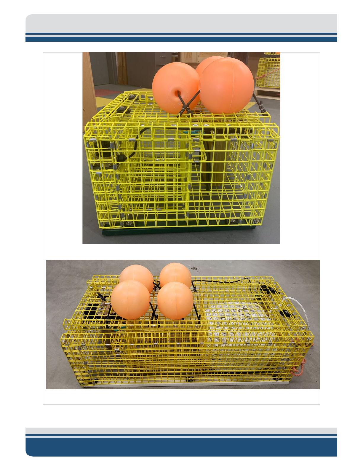
Figure 1-1: Modified 24.5-inch Cage .......................................................................................................... 1-2
Figure 1-2: 48-inch Modified Cage ............................................................................................................. 1-2
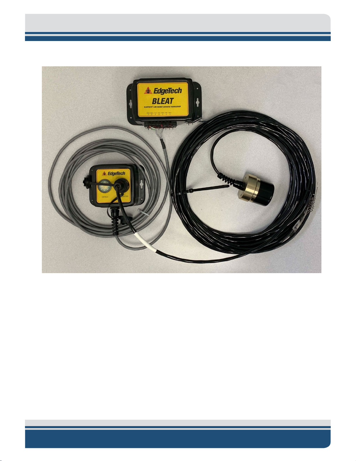
Figure 1-3: Bleat System: Command Box, Junction Box, and Dunking Transducer ................................... 1-3
Figure 1-4: Bleat Portable .......................................................................................................................... 1-3
Figure 1-5: Bleat Portable DunkingTransducer .......................................................................................... 1-3
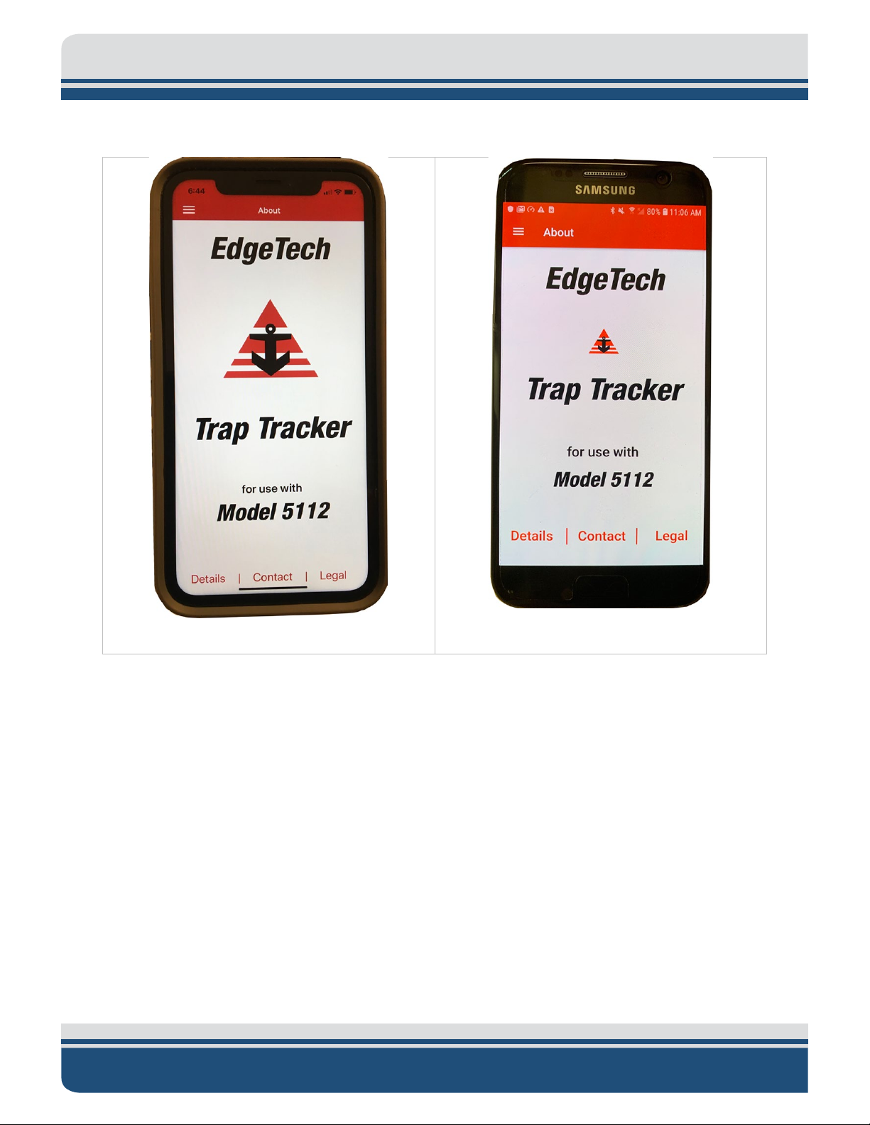
Figure 1-6: Trap Tracker IOS ...................................................................................................................... 1-4
Figure 1-7: Trap Tracker Android (Beta) .................................................................................................... 1-4
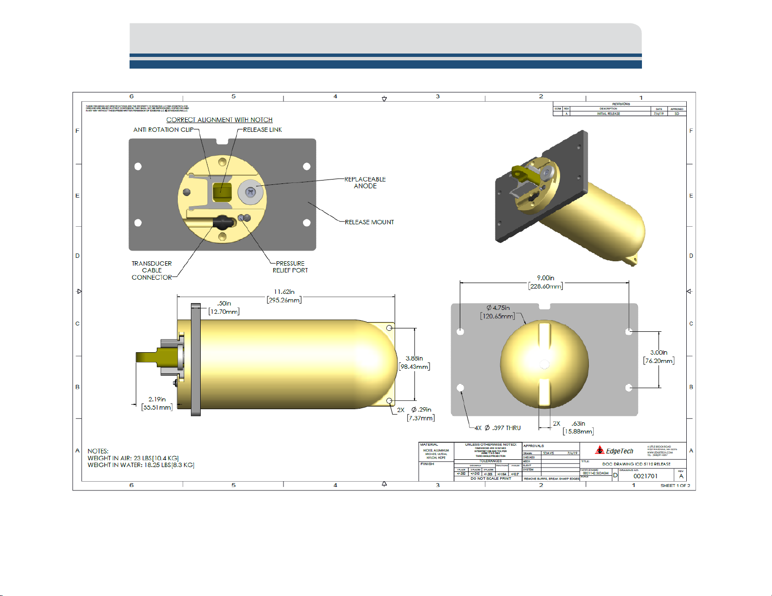
Figure 2-1: 5112 Release Mechanical Drawing pg.1 .................................................................................. 2-1
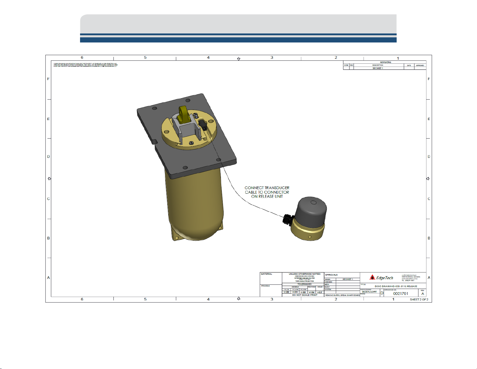
Figure 2-2: 5112 Release Mechanical Drawing pg.2 .................................................................................. 2-2
Figure 2-3: 22.5 Inch Cage Drawing ........................................................................................................... 2-1
Figure 2-4: 48-Inch Cage Mechanical Drawing .......................................................................................... 2-1
Figure 2-5: Bleat Command and Junction Box Mechanical/Electrical Drawing ......................................... 2-1
Figure 2-6: Bleat Portable Mechanical Drawing ........................................................................................ 2-1
Figure 3-1: Bleat Portable and Dunking Transducer ................................................................................. 3-2
Figure 3-2: Bleat Portable and Transducer Connection ............................................................................. 3-4
Figure 3-3: Bleat Command, Junction Box and Transducer ....................................................................... 3-5
Figure 3-4: Bleat Junction Box and Transducer Connection ...................................................................... 3-6
Figure 3-5: Rope Flaking into Basket ........................................................................................................ 3-17
Figure 3-6: Rope Basket Placement in Cage ............................................................................................ 3-17
Figure 3-7: Rope Lock Knot Positioning ................................................................................................... 3-18
Figure 3-8: Line and Bridle Connection .................................................................................................... 3-18
Figure 3-9: Floatation Cover Rope Position ............................................................................................. 3-19
Figure 3-10: Release Link Location on Floatation Cover\ ........................................................................ 3-20
Figure 3-11: Anti-Rotation Block Removal ............................................................................................... 3-20
Figure 3-12: Threading Release Link ........................................................................................................ 3-21
Figure 3-13: Release link Threaded and Anti-Rotation Block Back In Place ............................................ 3-21
Figure 3-14 Proper Release Link Orientation ........................................................................................... 3-21
Figure 3-15: Pin and Ring Lock Installation .............................................................................................. 3-22
Figure 5-1: Release Mounting Bolt Locations ............................................................................................ 5-1
Page 16

xvi
Figure 5-2: Release and Mounting Plate Removal ..................................................................................... 5-2
Figure 5-3 Release Orientation in Mounting Plate .................................................................................... 5-3
Figure 5-4: Unthreading Release Endcap Using Spanner and Strap Wrenches ......................................... 5-4
Figure 5-5: Battery Mounting Plate Removal ............................................................................................ 5-5
Figure 5-6: Battery Removal ...................................................................................................................... 5-5
Figure 5-7: Battery Mounting Plate Mounting........................................................................................... 5-6
Figure 5-8: Release Endcap and Mounting Plate Orientation ................................................................... 5-7
5112 Ropeless Fishing System 0022081_REV_A
Page 17

xvii
LIST OF TABLES
Table 2-1: Acoustic Release Mechanical Specifications ............................................................................. 2-5
Table 2-2: Acoustic Release Power Specifications .................................................................................... 2-5
Table 2-3: Acoustic Release Command Receiver Specification ................................................................. 2-5
Table 2-4: Release Commands, Responses and Command Functions ....................................................... 2-6
Table 2-5: Acoustic Release Environmental Specifications ........................................................................ 2-6
Table 2-6: 22 Inch Cage Mechanical Specifications ................................................................................... 2-1
Table 2-7: 48 Inch Cage Mechanical Specifications ................................................................................... 2-1
Table 2-8: Bleat Deck Box Mechanical Specifications ................................................................................ 2-1
Table 2-9: Bleat Deck Box Electrical Specifications .................................................................................... 2-1
Table 2-10: Bleat Deck Box Power Specifications ...................................................................................... 2-1
Table 2-11: Bleat Deck Box Mechanical Specifications .............................................................................. 2-1
Table 2-12: Bleat Deck Box Electrical Specifications .................................................................................. 2-1
Table 2-13: Bleat Deck Box Power Specifications ...................................................................................... 2-1
Table 2-14: Dunking Transducer Mechanical Specifications ..................................................................... 2-1
Table 7-1: Spare Parts, Suggested Vendors and Product Numbers ......................................................... 7-22
Page 18

1-1
1.0 OVERVIEW
The EdgeTech 5112 Ropeless Fishing System (RFS) was designed with fishers to eliminate the need for a
persistent vertical line to connect fishing gear to a surfaced buoy until just before retrieval. The intent is
alleviating possible whale and other marine-life entanglement and help prevent line tangles, cuts, tipped
cages, and other adverse effects of seafloor to-surface lines. The RFS consists of a modified fishing cage
with an attached EdgeTech 5112 rugged acoustic release and transponder, a BLEAT (Bluetooth® Low
Energy Acoustic Transceiver) Deck Box unit or Portable BLEAT deck box with hull-mounted or portable
dunking transducers and the EdgeTech Trap Tracker application running on an IOS or Android device. The
system is deployed like any other rope-and-buoy cage, independent or at the head or tail of a line of
unmodified fishing cages. The cage operates like a standard fishing cage but contains the 5112 release,
transponder, rope, and floats. Commands are made in the Trap Tracker phone application, sent by a
Bluetooth® wireless connection to the BLEAT deck box and dunking or hull-mounted transducers that send
the commands by an acoustic signal to a release attached to the cage. An in-range release receives the
command, acts, and replies to and with information in the Trap Tracker phone application. Commands
include deployment, ID information, status information, and retrieval. Cage retrieval is accomplished by
sending a unique recovery command to an in-range modified cage that responds by sending range
information to the phone application and mechanically releasing the line and buoys to the surface. The
line and buoys are retrieved like any other unmodified rope-and-buoy cage system. The system collects
and stores information during the entire process to help fisherman make decisions in the future. This
includes unit information, real-time status information, and enterable operational details.
1.1 Main System Components
The systems main components are:
A modified cage with EdgeTech 5112 Rugged Release, Transducer, Rope Basket, Line, and Floats attached.
Page 19
1-2 3.0 TECHNICAL DESCRIPTION
Figure 1-1: Modified 24.5-inch Cage
Figure 1-2: 48-inch Modified Cage
5112 Ropeless Fishing System 0022081_REV_A
Page 20
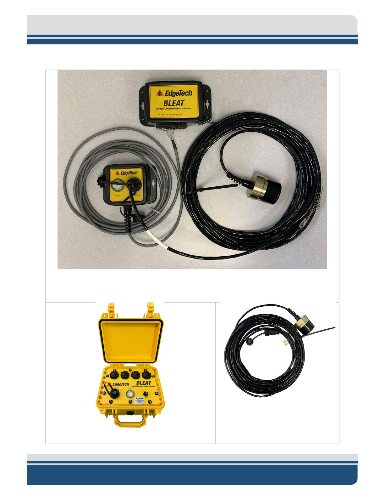
Bleat or Bleat Portable Deck Box and Transducer
1-3
Figure 1-3: Bleat System: Command Box, Junction Box, and Dunking Transducer
Figure 1-5: Bleat Portable
DunkingTransducer
Figure 1-4: Bleat Portable
Page 21
1-4 3.0 TECHNICAL DESCRIPTION
IOS or Android Mobile Application
Figure 1-6: Trap Tracker IOS
Figure 1-7: Trap Tracker Android (Beta)
5112 Ropeless Fishing System 0022081_REV_A
Page 22

2.0 SPECIFICATIONS
SPECIFICATION
VALUE
Depth rating:
500 meters (1,640 feet)
Maximum release load:
112 kg (247lbs)
Maximum static load:
225 kg (496 lbs)
Overall length:
35.5 cm (14 in)
Main diameter:
12 cm (14 in)
Weight in Water:
8.6 kg (19 lbs)
Weight in Air:
10 kg (22 lbs)
Housing Material:
Nickel-Aluminum-Bronze Alloy
Other Materials:
Buna-N, ULTEM, and Nylon
Release type:
Mechanical (motor-driven push off)
SPECIFICATION
VALUE
Main supplies:
4 Replacement 9-volt Alkaline
Average current drain:
<70uA
Design life (@ -2 degree C):
1 year
Design life (@ -2 degree C):
150 releases
SPECIFICATION
VALUE
Receiver Sensitivity
-78 dB re μPascal-meter
Transmit Source Level
178 dB re μPascal-meter
Command Frequency
17.5 kHz to 18 kHz
Specifications for the 5112 Ropeless Fishing System are provided in the subsections to follow.
2.1 5112 Acoustic Release Specifications
2.1.1 5112 Acoustic Release Mechanical Specifications
2-5
Table 2-1: Acoustic Release Mechanical Specifications
2.1.2 5112 Acoustic Release Power Specifications
Table 2-2: Acoustic Release Power Specifications
2.1.3 5112 Acoustic Release Command Receiver
Table 2-3: Acoustic Release Command Receiver Specification
Page 23

2-6 3.0 TECHNICAL DESCRIPTION
COMMAND
FUNCTION
ID
When received release serial number and range is transmitted.
When received replies with range to release, unit tilt and remaining battery
capacity
Does not send anything and no reply from release. It is Trap Tracker command that
operational details entered by the user to Trap Tracker.
Activates the mechanical release mechanism. Floats and line released to the
surface. Range and temperature are transmitted.
Activates the mechanical release mechanism. Floats and line released to the
surface. Range transmitted.
Operating:
-10 degree C to + 40 degree C
2.1.4 5112 Acoustic Release Standard Command Functions
STATUS
DEPLOY
RECOVER
RELEASE
saves the latitude and longitude of the phone or tablet when deployed and any
Table 2-4: Release Commands, Responses and Command Functions
2.1.5 5112 Acoustic Release Environmental Specifications
SPECIFICATION VALUE
Storage: (Batteries removed) -20 degree C to + 60 degree C
T
able 2-5: Acoustic Release Environmental Specifications
2.1.6 5112 Acoustic Release Mechanical Drawing
12 Ropeless Fishing System 0022081_REV_A
51
Page 24
2-1
gure 2-1: 5112 Release Mechanical Drawing pg.1
Fi
Page 25
2-2 3.0 TECHNICAL DESCRIPTION
gure 2-2: 5112 Release Mechanical Drawing pg.2
Fi
Page 26

2.2 5112 22.5 Inch Equipped Cage
SPECIFICATION
VALUE
Dimensions (LxWxH)
57.1cm(22.5in) x 57.1cm(22.5in) x 40.1cm(16in)
Weight in Air
37.6kg(83lbs)
Weight in Water
12.7kg(28lbs)
Table 2-6: 22 Inch Cage Mechanical Specifications
2-1
Page 27
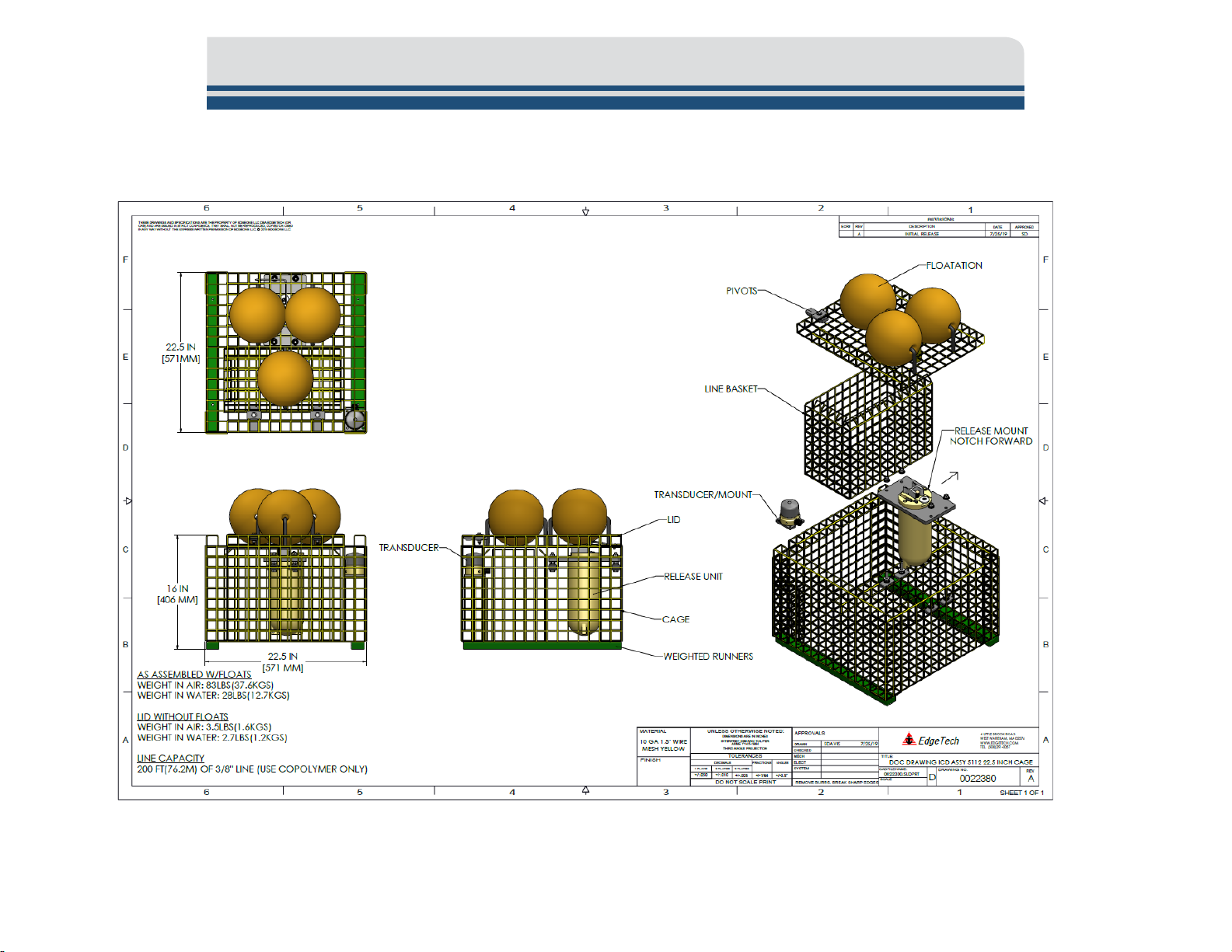
2.2.1 22.5 Inch Cage Mechanical Drawing
2-1
Figure 2-3: 22.5 Inch Cage Drawing
Page 28

2.3 5112 48 Inch Equipped Cage
SPECIFICATION
VALUE
Dimensions (LxWxH)
121.9cm(48in) x 57.1cm(22.5in) x 40.1cm(16in)
Weight in Air
47.6kg(105lbs)
Weight in Water
18.1kg(40lbs)
Table 2-7: 48 Inch Cage Mechanical Specifications
2-1
Page 29
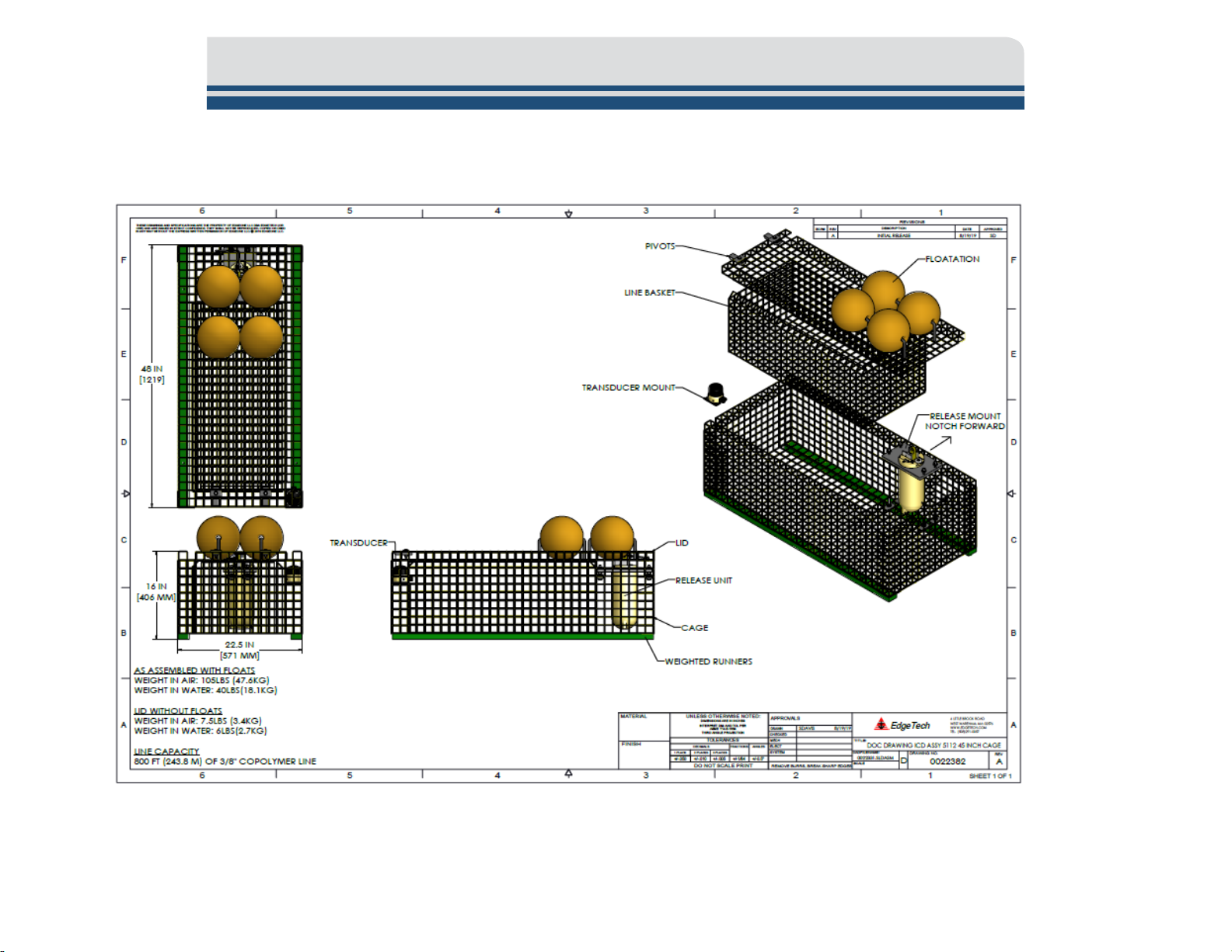
2.3.1 48-inch Cage Mechanical Drawing
2-1
Figure 2-4: 48-Inch Cage Mechanical Drawing
Page 30

2.4 Bleat Deck Box
SPECIFICATION
VALUE
Control Box Dimensions (LxWxH)
18.57cm(7.31in)x7.62cm(3.0in)x6.1cm(2.4in)
Control Box Weight
.91kg(2lbs)
Junction Box Dimensions (LxWxH)
13.49cm(5.31in)x8.26cm(3.25in)x6.1cm(2.4in)
Control Box Weight
.70kg(1.5lbs)
Cable Length
4.6m(15ft)
SPECIFICATION
VALUE
Source level
Variable, High/Low, 178 / 183 dB re 1 uPascal at 1 meter
Pulse width
12 mS
Interrogate frequency
18.0 kHz
Receive frequencies
24.0 & 25.0 kHz
Maximum range
4000 meters
Minimum range
0 meters
Beam pattern
Omni-Directional (in one hemisphere)
Transducer, 7.0 lbs (3.2) kg
SPECIFICATION
VALUE
External power supply
12v nominal, 4 amp peak load
Battery life
N.A.
Battery type
N.A.
2.4.1 Bleat Deck Box Mechanical Specifications
Table 2-8: Bleat Deck Box Mechanical Specifications
2.4.2 Bleat Deck Box Electrical Specifications
2-1
Weight in air Electronics Package, 7.0 lbs (3.2 kg)
Table 2-9: Bleat Deck Box Electrical Specifications
2.4.3 Bleat Deck Box Power Specifications
Table 2-10: Bleat Deck Box Power Specifications
Page 31

2.4.4 Bleat Deck Box Drawing
2-1
gure 2-5: Bleat Command and Junction Box Mechanical/Electrical Drawing
Fi
Page 32

2.5 Bleat Portable Deck Box
SPECIFICATION
VALUE
Dimensions (LxWxH)
26.93cm(10.6in)x 24.50cm(9.65in)x17.54(6.91in)
Weight
3.4kg(7.5lbs)
SPECIFICATION
VALUE
Source level
Variable, High/Low, 178 / 183 dB re 1 uPascal at 1 meter
Pulse width
12 mS
Interrogate frequency
18.0 kHz (standard)
Receive frequencies
24.0 & 25.0 kHz
Maximum range
4000 meters
Minimum range
0 meters
Beam pattern
Omni-Directional (in one hemisphere)
Commands supported
XACS
SPECIFICATION
VALUE
Battery type
8 each Alkaline Magnesium “C” Cell Batteries
2.5.1 Bleat Portable Deck Box Mechanical Specifications
Table 2-11: Bleat Deck Box Mechanical Specifications
2.5.2 Bleat Portable Deck Box Electrical Specifications
2-1
Table 2-12: Bleat Deck Box Electrical Specifications
2.5.3 Bleat Portable Deck Box Power Specifications
Battery life 800 hours quiescent
Table 2-13: Bleat Deck Box Power Specifications
Page 33

2.5.4 Bleat Portable Deck Box Drawing
2-1
Figure 2-6: Bleat Portable Mechanical Drawing
Page 34

2.6 5112 Dunking Transducers
SPECIFICATION
VALUE
Hydrophone: Diameter 2.81(71.4mm)”, Length 3.10(78.7mm)”
2.6.1 Dunking Transducer Mechanical Specifications
Transducer Size 65’ (20m) x 0.375” (9.5mm) Kevlar reinforced cable
Table 2-14: Dunking Transducer Mechanical Specifications
2-1
Page 35

3-2 5.0 MAINTENANCE
3.0 SETUP AND ACTIVATION
EdgeTech designed the 5112 Ropeless Fishing System to be easy to set up and activate for operation.
Instructions for this process are provided in the subsections to follow.
3.1 Bleat Deck Box Installation and Activation
3.1.1 Bleat Portable Installation and Activation
Figure 3-1: Bleat Portable and Dunking Transducer
The Bleat Portable can be installed anywhere on the vessel that meets these parameters.
• The Bleat Portable Unit must be within Bluetooth® wireless range of Trap Tracker enabled devices.
Edgetech suggests a distance no greater than 32 feet (10 meters).
5112 Ropeless Fishing System 0022081_REV_A
Page 36

3-3
• The Bleat Portable Unit must be deployed within a cable length that allows the transducer to be
lowered off the side of the vessel and several meters below the draft of the boat.
• Box and Cable Size and Weight specification and a drawing can be found in
DECK BOX section of this manual.
Battery Installation:
8 Alkaline Magnesium “C” Cell Batteries are required for operation. They are installed in pairs in battery
compartments located on top of the Bleat Portable. To install batteries, unthread cap from battery
holders, place battery pair into battery holder (cap and bottom have battery orientation indicators) and
rethread cap by pressing down firmly and rethreading cap until tight.
THE BLEAT PORTABLE
To Connect the System:
1. Connect the transducer cable female end into the male connector marked Transducer on the
Junction Box. There is a tab on the female connector that lines up with a tab slot on the male
connector. Line up tab and tab slot and push in gently until completely seated. Thread outer
fastener until tight.
Page 37

3-4 5.0 MAINTENANCE
Figure 3-2: Bleat Portable and Transducer Connection
To Activate the System:
1. Turn the system on by turning the power switch to the on position. You will know the system is
on when the detect light on the junction box flashes red, and an audible beep is heard.
2. Once activated Trap Tracker capable devices can be paired with the system, and acoustic
transducers can be deployed to communicate with the 5112 releases.
5112 Ropeless Fishing System 0022081_REV_A
Page 38
3.1.2 Bleat Deck Box Installation and Activation
3-5
Figure 3-3: Bleat Command, Junction Box and Transducer
The Bleat System’s Control box and Deck box components can be installed anywhere on a vessel meeting
these parameters.
• The Control Box will need to be installed within power cable length of a power source and
preferably within Bluetooth® range of the likely locations Trap Tracker enabled devices will be
used. Edgetech suggests a Bluetooth® pairing distance no greater than 32 feet (10 meters).
• The Junction Box should be installed within cable length (15ft) of the control box and within a
transducer cable length that can deploy a transducer off the side of the boat into the water several
meters below the draft of the vessel.
• Box and cable size and weight specification and a drawing can be found in the B
section of the manual.
To connect the system:
1. Ensure the Control box is connected to the Junction box.
LEAT DECK BOX
Page 39

3-6 5.0 MAINTENANCE
2. Connect the transducer cable female end into the male connector marked Transducer on the
Junction box. There is a tab on the female connector that lines up with a tab slot on the male
connector. Line up the tab and tab slot and push in gently until completely seated. Thread the
outer fastener until tight.
Figure 3-4: Bleat Junction Box and Transducer Connection
To Activate the System:
1. Connect the Control Box to the vessel’s 12-Volt DC power source. The system is on when power
is connected. You will know the system is on when the detect light on the junction box flashes
red, and an audible beep is heard. The deck box will beep once every five minutes when on and
idle.
2. Once activated Trap Tracker capable devices can be paired with the system, and acoustic
transducers can be deployed to communicate with the 5112 releases.
5112 Ropeless Fishing System 0022081_REV_A
Page 40

3-7
1. Select the App Store Icon on your IOS Device
2. The Apple App store will be displayed. Click
3. The Track Tracker purchase page will be
like to purchase again and subscribe.
Purchase and accept all confirmations to
move forward.
3.2 Trap Tracker Mobile Application Installation and Subscription Activation
3.2.1 iPhone Trap Tracker
The iPhone version of the Trap Tracker Applications can be downloaded from Apple’s App Store.
To do so:
(iPhone, iPad)
the search button and type “EdgeTech Trap
Tracker” into the search field. When the
EdgeTech Trap Tracker Application appears
select it.
displayed. To buy the application, press the
blue button with the product’s price on it. A
series of screens will appear asking if you’d
Page 41

3-8 5.0 MAINTENANCE
2. Go to the Trap Tracker Menu by selecting
line menu icon on the upper
left-hand side of the screen.
3. Select Charts from the left side menu.
3.2.2 Installing Navionics Nautical Charts in Trap Tracker.
Trap Tracker’s Chart feature gives users the ability to display cage locations on a Navionics provided
nautical chart.
To do so:
1. Purchase the Navionics Boating Application in either the Apple App Store (iPhone) or Google Play
Store (Android). This will provide access to download their Boating Application and provide a login Email address and password that you’ll use in the Trap Tracker Application to gain access to their chart
service.
the three-
5112 Ropeless Fishing System 0022081_REV_A
Page 42

3-9
4. The Chart screen will appear. Select the
the Chart option
popup at the bottom of the screen.
5. Click Login Navionics to login to the service.
mail address and
three-dot icon on the upper right side of
the screen to view
Enter your Navionics Epassword at the prompts.
Page 43

3-10 5.0 MAINTENANCE
6. Once logged in, press the three-dot menu
7. The chart display will appear with a green box
anchored at each corner with a green dot.
Manipulate the size and shape of this box by
download button when ready. Your chosen
icon on the upper left again, and select
Download Charts.
pressing and dragging each dot with your finger
until the desired chart area is created. Press the
Navionic map area should appear.
5112 Ropeless Fishing System 0022081_REV_A
Page 44

3-11
1. Select the three-line menu button at the top
of Trap Tracker.
2. Select the Settings Button from the left side
menu.
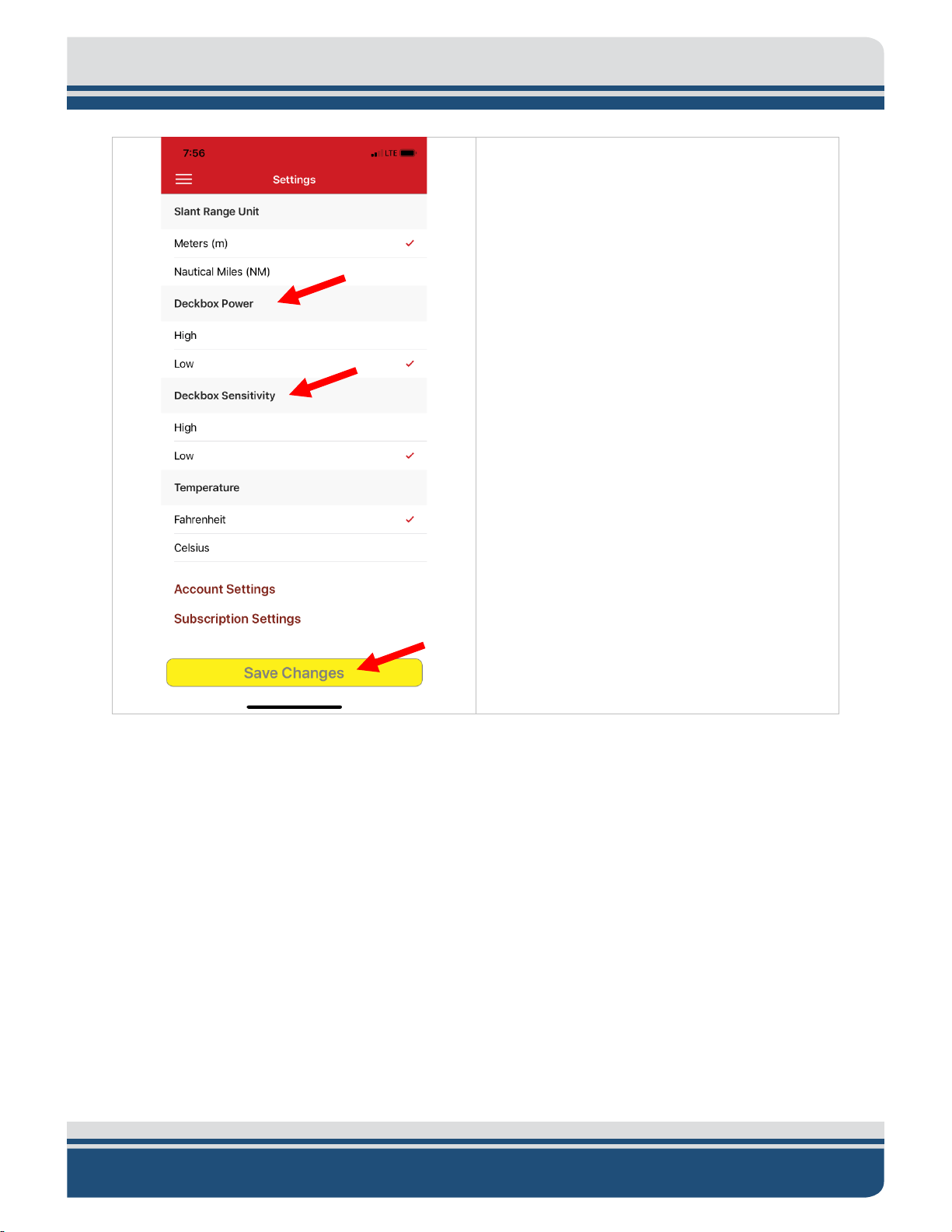
3.2.3 Trap Tracker Settings and Options
Trap Tracker provides settings the fisher can use to switch measurements systems (U.S. Customary and
Metric), change Deckbox-transponder settings, change account information, and change subscription
information.
To do so:
Page 45

3-12 5.0 MAINTENANCE
3. The Setting screen will appear, and its
measurement to either meters or nautical
miles. Selecting either line will change the
setting and move the checkmark to the
Sets the power of the
Trap Tracker Account Settings Screen.
press the Save Changes
functions are as follows.
Slant Range Unit: Sets the units of slant range
chosen unit of measurement.
Deckbox Power:
outbound acoustic signal from the transducer
connected to the Deckbox.
Deckbox Sensitivity: Sets the sensitivity of the
transducer attached to the deckbox.
Temperature: Sets the Temperature units of
measurement to either degree Fahrenheit or
Degrees Celsius.
Account Settings (See Figure below): Opens
the
Account Name, Address, and Fishing License
Screen information can be modified.
Subscription Settings (See figure below):
Opens the IOS devices Subscription Screen. If
Subscribed, a Trap Tracker Entry will exist that
can be modified by selecting it.
After any changes,
button to save them.
5112 Ropeless Fishing System 0022081_REV_A
Page 46

3-13
3.3 Connecting Track Tracker device to Bleat Deck Box.
Your IOS device and the Bleat Deck Box are both equipped to use Bluetooth® Wireless, but both must be
on, positioned well, and paired to work correctly.
Bluetooth® wireless technology is limited by range and can get blocked or degraded by metal structures
or electrical interference. We suggest not being any farther than 32 feet (10 meters) away.
Bluetooth® wireless technology is always enabled on the Bleat Deck box but may need to be enabled on
the IOS device.
To do so:
Page 47

3-14 5.0 MAINTENANCE
1. Click the Settings Button on your IOS Device
2. The Settings screen will open. Find the
Bluetooth® wireless on.
3. The Bluetooth® settings will appear. To turn
Bluetooth® line. If it is on, a data block on the
right is marked as “On.” If it is off, the data
block will display “Off.” Select the line to turn
Bluetooth® wireless on, slide to radio switch
on the right to green on position.
5112 Ropeless Fishing System 0022081_REV_A
Page 48

To pair the devices together:
1. Open Trap Tracker on the IOS device. Press
hand side of the screen.
2. The Trap Tracker menu will appear on the
down.
3-15
the three-line menu button on the upper left-
left. Select Pair Deck Box from the drop-
Page 49

3-16 5.0 MAINTENANCE
3. The Pair Deck Box screen will appear, and the
4. Once a device is found, it will be listed
pair when in range.
application will be searching for a Bleat Box
in range. The twirling circle indicates the
search is occurring. If it stops and another
scan is needed, press the yellow Scan button.
without a twirling icon next to it in the Found
list. Select it to pair. A green checkmark will
appear to the right of the device entry once
connected. It will always be listed under the
Found header after the first pairing and will
3.4 Release Cage Setup
Setting or resetting the release cage involves packing the rope and float cover and arming the release for
deployment. Both processes are designed to be fast, easy, and with minimal interference to normal fishing
activities.
5112 Ropeless Fishing System 0022081_REV_A
Page 50

3.4.1 Setting the Rope and Float Cover
1. Randomly flake the rope into the rope basket, leaving enough slack on each end to secure the top
bridle.
2. Set the rope basket into the 5112 cage and secure the basket with hooks.
To do so:
end to the floatation cover and the end coming from the bottom of the rope basket to the cage
3-17
Figure 3-5: Rope Flaking into Basket
Figure 3-6: Rope Basket Placement in Cage
Page 51

3-18 5.0 MAINTENANCE
3. Tie lock knots at both ends at length that put the knots inside the cage. This will prevent the rope
4. Secure the bottom end of the line to the bridle.
5. Secure the top end of the line to the floatation cover.
line from being pulled through.
Figure 3-7: Rope Lock Knot Positioning
Figure 3-8: Line and Bridle Connection
5112 Ropeless Fishing System 0022081_REV_A
Page 52

3-19
Figure 3-9: Floatation Cover Rope Position
6. Secure the floatation cover on the cage by sliding it into position mounting tabs first. The tabs should
fit under the supporting length of the cage above them.
3.4.2 Arming the 5112 Release
The 5112 is armed when the release link has been screwed back into the rotation lock and held in place
by the securing locking pin and ring.
Page 53
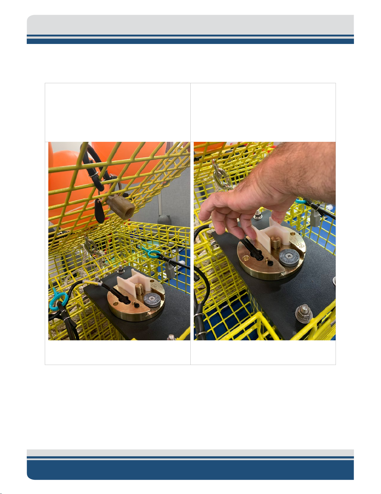
3-20 5.0 MAINTENANCE
1. Lift the floatation cover. The 5112 release link
top of the cage. Separate the Release Link
2. Pinch and pull the anti-rotation block back
To do so:
is attached to a rubber cable connected to the
from the rubber cable by unfolding the lock
ring from and sliding the release link from the
pin.
from the release’s threaded bolt.
Figure 3-10: Release Link Location on Floatation
Cover\
5112 Ropeless Fishing System 0022081_REV_A
Figure 3-11: Anti-Rotation Block Removal
Page 54

3-21
3. Thread the release link completely with the
necessary to unthread the release link a
4. Pinch and slide the anti-rotation block into
5. Set the floatation cover back into place. It
eye facing fore and aft of the cage. It may be
quarter to half turn to properly orient the eye.
place, securing the release link in place.
Figure 3-12: Threading Release Link
should fit and be flush with the rest of the
cage. The eye hole of the release link should
rise just above the cage.
Figure 3-13: Release link Threaded and Anti-
Rotation Block Back In Place
Figure 3-14 Proper Release Link Orientation
Page 55

3-22 5.0 MAINTENANCE
6. Reattach the pin, folding the ring back into place.
Figure 3-15: Pin and Ring Lock Installation
3.4.3 Dry Testing the System
Two dry tests can be performed to ensure the release will respond to commands and send back data to
the Trap Tracker Application. The tests require that the release is listed in the device’s Trap Tracker
Underwater Units list. These tests also require the user knows how to use the system and understands
how it should work. If this is the first use, the release hasn’t been scanned into the Underwater Unit list
yet, or there are further questions, detailed instructions and explanations are provided in the O
INSTRUCTIONS section of this manual.
5112 Ropeless Fishing System 0022081_REV_A
PERATING
Page 56

3-23
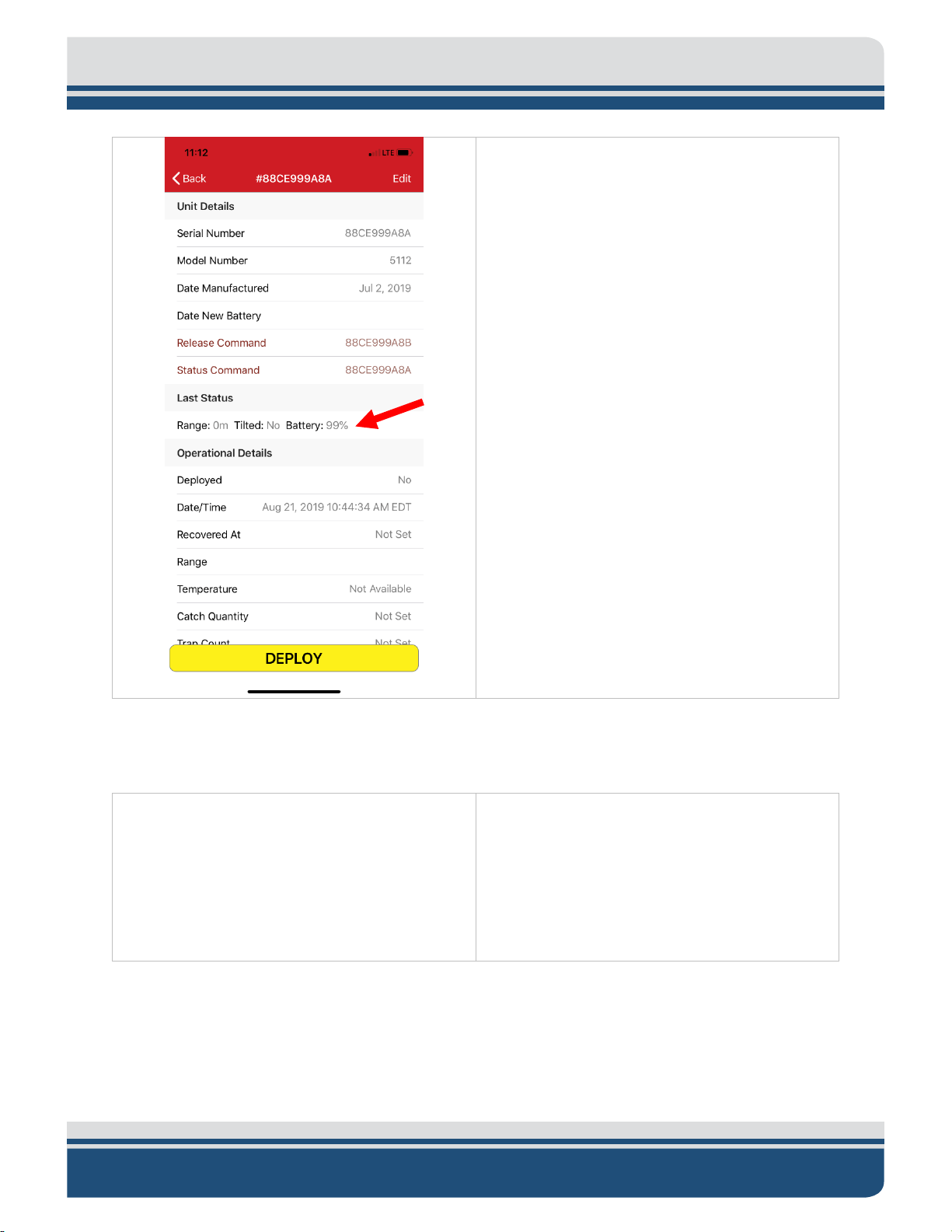
3.4.3.1 Status Command Test
The Status Command test tests the ability to communicate with the release. The objective is to see an
updated range, tilt, and battery values in the Last Status Line of Unit Information Screen.
To do so:
1. In the Trap Tracker application press, the three-lined Trap Tracker Menu button, select Underwater
Units and select the specific release to test by pressing its serial number. Notice the line under Last
Status. If “No Data Available” the unit has never sent a status command. If a Range, Tilted and Battery
values are displayed, take note of what they are so you can notice a change when the status command
is sent.
2. Power on the Portable Bleat box if this has not yet been done. Instructions for this can be found in
LEAT DECK BOX INSTALLATION AND ACTIVATION section of this manual.
the B
3. Ensure the Track Tracker enabled device you are using has a Bluetooth® connection to the Bleat Box.
This can be checked and reconnected by selecting Pair Deck box from the Trap Tracker Menu. If
disconnected follow the instructions in the C
ONNECTING TRACK TRACKER DEVICE TO BLEAT DECK BOX section
of the manual to reconnect.
Page 57

3-24 5.0 MAINTENANCE
4. Scan the 5112 release NFC tag if this specific release hasn’t already been added to the Underwater
Unit List.
5112 Ropeless Fishing System 0022081_REV_A
Page 58

5. Go to the Underwater Unit List and select the specific unit.
3-25
Page 59

3-26 5.0 MAINTENANCE
6. In the Unit Information Screen Send the Status
Command to the release by pressing the
Status Command text in the Release’s
Underwater Unit information screen.
5112 Ropeless Fishing System 0022081_REV_A
Page 60

7. Look at the Last Status section on the Unit
Information Screen. Updated range, titled and
1. Power on the Bleat Box and Transducer if using Bleat Portable.
2. Scan the 5112 release NFC tag if this specific release hasn’t already been added to the Underwater
battery values should be populated.
3-27
3.4.3.2 Release Command Test
The Release Command Test’s objective is to ensure that the release receives the release command, the
release link completely unthreads from the release’s threaded shaft, and a successful message popup is
returned.
To do so:
Unit list of Trap Tracker.
Page 61

3-28 5.0 MAINTENANCE
3. Go to the Underwater Unit List and then select
serial number text.
4. The Unit Information Screen will appear.
Release command line.
the specific unit to be tested by pressing the
Press the Release Command text on the
5112 Ropeless Fishing System 0022081_REV_A
Page 62

5. The release link will then unthread separating
the release link from the release and
floatation cover from the cage.
A Success popup will appear showing the
outcome of the test, serial number, and range
to the unit. Press Ok to close the popup.
Try again If a failure message is received. If the
test continues to fail, contact CUSTOMER
SERVICE for support.
3-29
Page 63

4-30 5.0 MAINTENANCE
4.0 OPERATING INSTRUCTIONS:
4.1 Cage Deployment:
4.1.1 Add the Release To Trap Tracker
A release should be added to the Trap Tracker Underwater Unit List of any device used to send commands
to it. Releases are added using an NFC scan-in function of the Trap Tracker software or if the device is not
NFC capable the release can be entered manually.
4.1.1.1 Add Release By Scanning the Cage NFC Tag
The NFC Tag needs to be scanned, or the information needs to be manually added to be added to the Trap
Tracker Application’s Underwater Unit list on your device. This only has to be done once, unless it has
been removed from the list.
NOTE If your device doesn’t have NFC scanning capability, the
underwater unit information can be manually entered into the current
device. A second NFC capable device could also be used by scanning the
tag and then sync the device with the cloud to get the required release
information. See the NFC SCANNING NOT FUNCTIONAL troubleshooting
section of this manual for instructions on how to address this.
CAUTION. Do not forget this step as Trap Tracker can only send recover
commands to releases added to its list. If a cage was accidentally
deployed without scanning, see CAGE DEPLOYED WITHOUT SCAN in
Troubleshooting to learn how to add a cage that hasn’t been scanned.
5112 Ropeless Fishing System 0022081_REV_A
Page 64

To Scan:
1. Locate the scannable NFC tag that is attached to the cage.
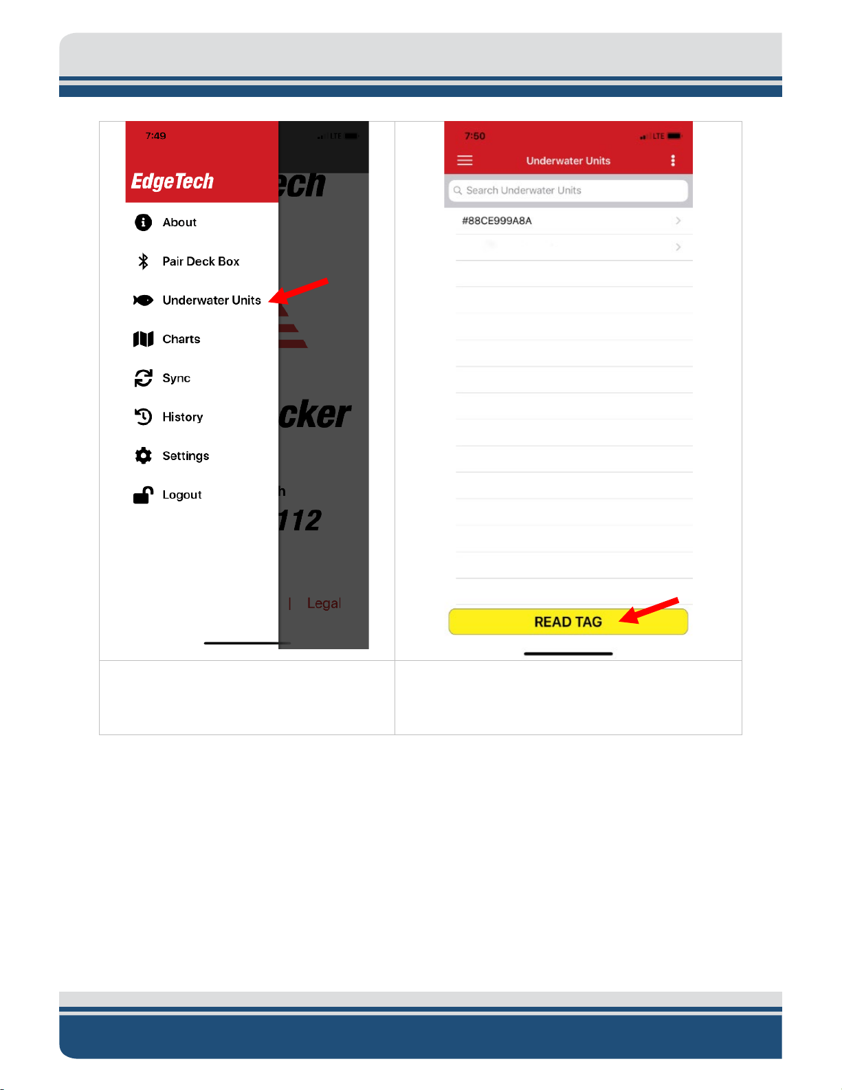
2. In Trap Tracker, select the 3-line Trap
3. Select Underwater Units from the left side
4. The Underwater Units list will appear. This displays
device above the tag face.
4-31
Tracker menu button on the upper left
side of the Trap Track screen.
menu that appears.
a list of cages added to the Trap Tracker Account
used on the device you are using by deployment
status and serial number. Press the Yellow Read
Tag button and start scanning by moving the
Page 65
4-32 5.0 MAINTENANCE
5. The application will start scanning for a
of the Android phone near the NFC tag
6. The new unit will be added to the Underwater
tag. You will see a Ready to Scan message.
Hold the top of the iPhone or rear center
5112 Ropeless Fishing System 0022081_REV_A
Units list on your IOS device.
Page 66

4-33
4.1.1.2 Manually Adding a Release Into Trap Tracker
A release can be manually added to Underwater Units List in Trap Tracker.
To do so:
Page 67

4-34 5.0 MAINTENANCE
1. Select the three-line Trap Tracker Menu
2. Select Underwater Units from the left side
Button.
menu.
5112 Ropeless Fishing System 0022081_REV_A
Page 68

4-35
3. Select the three-dot options menu on the
4. Select Add Unit Manually from the popup that
5. The Add Unit screen will appear. A release serial number and release command will be needed to
model number, date
This number may also be found laser-etched on the release end cap, on the NFC tag on the
upper right-hand side of the Underwater Units
screen.
appears.
add it to the Underwater Units list. Optionally you can also add the
manufactured, date new battery. Status Command is automatically populated when the serial
number is entered as they are the same values.
To find information on these parameters:
• Serial number: A required 10-digit number located on the card received with the product.
Page 69

4-36 5.0 MAINTENANCE
release and in the Trap Tracker History of any device that has had the release listed as an
underwater unit.
• Model Number: 4 digit model number. 5112 is currently the only model number used.
• Date Manufactured: Can be found on the index card provided with the product. It may also
be found in the Trap Tracker Underwater Unit Screen of any device that has had the release
listed as an underwater unit. This value is not required.
• Date New Battery: Enter the date of the last battery change.
• Status Command: This number is auto-populated when Serial Number field is entered as
they are the same.
• When complete press the Yellow Add Unit button at the bottom. The Added unit will now
appear in the Underwater unit list.
5112 Ropeless Fishing System 0022081_REV_A
Page 70
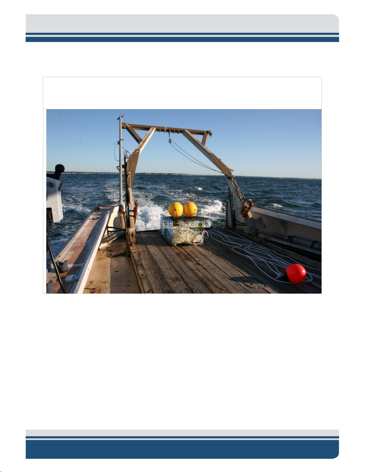
4.1.2 Deploy the Cage or Line of Cages and Mark them As So in Trap Tracker
1. Deploy the cage as you would any other fishing cage and immediately mark the cage as
deployed in Trap Tracker. You want to try as soon as possible after the cage leaves the vessel
as the position recorded is that of the IOS devices GPS location.
4-37
Page 71

4-38 5.0 MAINTENANCE
2. Open Trap Tracker, go to Underwater
3. The unit information screen will appear.
Press the deploy button to change the
4. A popup will appear asking if you’d like to
5. If a trap line is chosen, a further menu is
provided that will open with a counter
. This process
of cages is following it off the vessel. The
Units and select the release deployed by
selecting the serial number in the list.
status of the cage to deployed.
deploy a trap line or a single trap point.
Select your preference.
5112 Ropeless Fishing System 0022081_REV_A
that is counting seconds
assumes you pressed the deploy button as
the first cage was released and that a line
Page 72

4-39
Finish Button is pressed when the last
cage in the line leaves the boat.
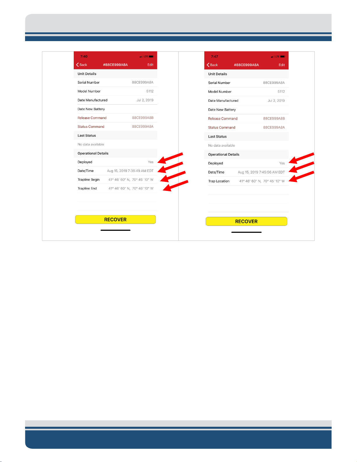
6. Once a trap line has been deployed, notice
A deployment Date and Time has been
End latitude and longitude
have been entered.
7. If the single trap point option was
notice the change in the Unit
Information screen under operational
A Deployment date and time has been
the change in the unit information screen
under Operational Details.
• The Deployed Status has been updated to
Yes.
•
entered.
• A Trap Line Begin latitude and longitude
has been entered.
• A Trap Line
selected,
details.
• The Deployed Status is Yes.
•
entered.
• A Cage Location latitude and longitude
has been entered
Page 73
4-40 5.0 MAINTENANCE
4.2 Cage Recovery
4.2.1 Use Trap Tracker to Navigate Position of Cage Release
The 5112 Release point location can be found by looking in the Unit Information Display or Chart Display
in Trap Tracker. A best practice is to press the Update button in the Chart Display to make sure everything
is up to date, and the latest data is presented.
4.2.1.1 Syncing
Syncing is updating both the device’s Trap Tracker application and the account information stored on Trap
Tracker’s cloud-based storage with the latest information on the release. Syncing occurs automatically
when Trap Tracker is opened or closed on an internet-connected device, or a change is made in the
Underwater Unit list, Unit Information Screen or Unit History. Manual syncing may be required if the
device Trap Tracker is installed on is disconnected from the internet during any phase of deployment or
recovery or if you use more than one device with the same Trap Tracker account. If multiple devices are
used a best practice is to sync at the end of the day.
5112 Ropeless Fishing System 0022081_REV_A
Page 74

NOTE Syncing only occurs within one Trap Tracker account. If the release
1. Go to Trap Tracker Settings by clicking the
2. The sync screen will appear. It displays a
the last sync. Press the Sync button to
nc button was pushed. The
what is stored in the database.
exists in the database of two different accounts they will not sync, it is
best practice to use one account for all of your devices.
To Manually Sync:
4-41
three-line Menu button and select Sync.
list of databases to sync with (currently
Fisheries) and a History with the date of
sync. If successful, the Last Synced time
should update to match the date and time
the Sy
Underwater Unit list information on the
device you are using should now match
4.2.1.2 Trap Tracker Chart Display
The Trap Tracker Chart Display Screen provides a means to see the marked locations of all 5112 equipped
cages added to the device’s Underwater Unit List on a chart display and any other 5112 equipped cage
Page 75

4-42 5.0 MAINTENANCE
1. Press the three-line Trap Tracker Menu button
2. The chart will appear. Notice your position
within five nautical miles of the device. This display can be connected to
THE NAVIONICS CHART SERVICE that
provides a useful and informative map background to help navigate to release positions.
To use:
and select Charts from the Trap Tracker menu.
data is marked with the red arrow and trap
positions are marked with pins Red Pins are
your trap positions and orange pins are others
cage positions.
5112 Ropeless Fishing System 0022081_REV_A
Page 76

3. Press the Update button to pull in updated
information from the fisheries database. This
locations within 5 miles of the device’s
nd you
will have to hit the Update button
The system pulls in data of units
will display the location of other 5112 cage
current position.
• This does not automatically update
as your position changes, a
again as you reposition from the 5mile zone.
•
within 25 miles to address internet
connectivity intermittency at sea but
only displays 5 miles at one time.
4-43
Note-Trap Tracker can also export this information in a .gpx file for use in
map plotters. Information on that can be found in the EXPORTING GPX UNIT
DATA IN CHARTS section of this manual.
4.2.1.3 Trap Tracker Underwater Unit Screen Position
The Underwater Unit display for units provides the latitude and longitude of the location where the deploy
command was issued.
Page 77

4-44 5.0 MAINTENANCE
4.2.2 Use Transducers and Trap Tracker’s Status Command to Find A 5112 Release
Once the fishing vessel is relatively close (<300 yards) of the marked position in Trap Tracker, use a
deployed transducer and Trap Tracker’s Status Command to localize a submerged release to position the
vessel in visual range of the surfacing point of the line float.
5112 Ropeless Fishing System 0022081_REV_A
Page 78

4-45
4.2.2.1 Transducer Deployment and Usage
Medium frequency dunking transducers are used to communicate with 5112 acoustic releases. They do
so by sending an acoustic signal through the water that the release reacts to when detected. The 5112
responds by carrying out a command and returning an acoustic signal that the transducer detects and
sends to the Bleat Deck Box for interpretation. The Bleat box then transmits information over a Bluetooth®
wireless connection to the Trap Tracker enabled device.
To Use a Transducer:
1. The vessel should be stopped or slowed as much as possible with as few obstacles as possible between
it and the release’s position.
2. Ensure the transducer cable is mated to the marked transducer connector on the top of the unit. If
you have a Bleat portable system, ensure the Bleat transceiver and Transducer control box are
properly connected. If you have any questions, please review the B
ACTIVATION section of this manual.
3. Turn the portable Bleat unit on by flipping the power switch to the on position. The mounted Bleat
system is on when the power is on. You will know it is on when the light on the deck box flashes red,
and an audible beep pattern is heard.
4. Open Trap Tracker on the iPhone and check that it has paired to the Bleat box with Bluetooth®
wireless. If it is not, go to the C
ONNECTING TRACK TRACKER DEVICE TO BLEAT DECK BOX section of this manual
for instructions on how to pair the devices.
5. Carefully lower the transducer off the side of the boat facing the likely location of the release and
away from any engine or propeller noise or water disturbances.
6. Submerge the transducer head several feet below the water surface so the transducer can be used to
send commands and receive responses from a deployed release.
7. Commands can be sent from Trap Tracker at this point.
LEAT DECK BOX INSTALLATION AND
Transducer settings can be changed to meet different water and environmental conditions. These can be
changed in the Trap Tracker Settings.
Page 79

4-46 5.0 MAINTENANCE
1. Select the three-line Trap Tracker Menu
2. Select Settings from the left side menu.
To do so:
button.
5112 Ropeless Fishing System 0022081_REV_A
Page 80
3. The Settings screen will appear. Transducer
settings can be
changed by selecting either
High or Low Deckbox Power and Deckbox
releases at longer distances or if there are
Sensitivity settings. This is done by pressing
the High and Low setting text for each. When
done, a checkmark will appear on the right
side of the chosen line. Press the Save any
changes made.
The low default settings will work for most
conditions. High settings can be used to detect
difficult acoustic conditions.
4-47
4.2.2.2 Trap Tracker Status Update Function
The Status Command is useful in localizing a release as it provides an updated range, tilt, and battery
values in the Last Status Line of Unit Information Screen. The range value can be used to position the
vessel in a good spot to send the Recovery Command and spot the floats and line when they surface.
Page 81

4-48 5.0 MAINTENANCE
1. In Trap Tracker, select the three-line Trap
enu button and select Underwater
Units from the Trap Tracker Menu.
2. The Underwater Unit List will appear. Select
selecting the serial number text in its line.
3. The Unit Information Screen will appear.
Notice the line under the Last Status
To do so:
Track M
the Unit to send the Status command to by
•
header. If the field below displays, “No
Data Available,” the unit has never sent a
status command.
• If a Range, Tilted and Battery values are
displayed, the unit has sent a Status
command and received a return that
populated these fields. Take note of what
they are so you can notice a change when
the status command is sent, and new field
data is returned.
Send the Status Command to the release by
pressing the Status Command text in the Unit
Information Screen.
5112 Ropeless Fishing System 0022081_REV_A
Page 82
4-49
When the release receives the Status Command, it
will respond by populating Range, Tilted and
Battery values under Last Status in the Unit
an be
1. To recover a 5112 Acoustic Release go to the
Unit Information Screen for the unit to be
recovered and press the yellow recover
2. A Recover Unit popup will appear. Press the
When the release receives the recover
ease mechanism will be
disconnects the floatation
to the surface for recovery.
Information screen.
Range: Distance in meters to the release. Useful in
positioning the boat for recovery. It c
changed to nautical miles in Trap Tracker Settings.
See the
of this manual for instructions.
Titled: Either Yes or No. Tilted is defined as an
angel greater than 45⁰.
Battery: Percentage of full charge displayed.
TRAP TRACKER SETTINGS AND OPTIONS section
4.2.3 Use Transducer and Trap Tracker to Send the Recover Command
button at the bottom.
Red recover button to Recover the Unit.
command, the rel
activated. This
cover from the cage, that then carries the rope
Page 83

4-50 5.0 MAINTENANCE
3. The Recovered window will be displayed. This
Once completed, the Units information will be
are displayed.
window gives a final range and allows you to
enter the Catch Quantity and Trap Count
values. Press Finish when complete.
updated. Notice that:
• The Deployed Status is No.
• The Date and Time have been updated to
the recovery date and time.
• The Recovered at position data has been
updated to the position of the IOS device
when the Recover button was pushed.
• The water temperature at recovery is now
displayed.
• If entered, Catch Quantity and Trap Count
5112 Ropeless Fishing System 0022081_REV_A
Page 84

4-51
4.2.4 Trap Tracker ID Command
The Trap Trap Tracker ID Command returns the serial number and range of a release in range.
Page 85
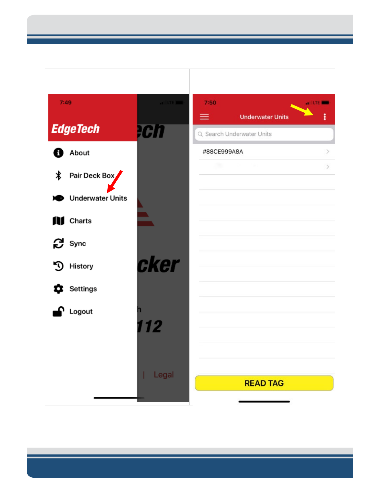
4-52 5.0 MAINTENANCE
1. In Trap Tracker select the three-line Trap
u button and select Underwater
Units from the Trap Tracker menu.
2. The Underwater Unit List will appear. Select
dot Underwater Unit List options
button on the top right side of the screen.
To do so:
Track men
the three-
5112 Ropeless Fishing System 0022081_REV_A
Page 86

3. The Underwater Unit List popup list will
appear. Press the Send ID Command
button to send the ID Command.
If communication is successful, a Success popup with
again.
4-53
the release Serial Number and range will appear. If a
failure occurs, reposition or increase power and try
4.2.5 Sending Commands to Releases Not In The Underwater Units List
It is possible to send Commands to releases not added to a specific Trap Tracker Unit List. This is most
useful to fisheries enforcement and limited to just the ID, Status and Release Commands. In the case of
Status and Release Commands, a user must have the ten-digit command codes to use them. The release
must be able to receive the acoustic signal to respond.
Page 87
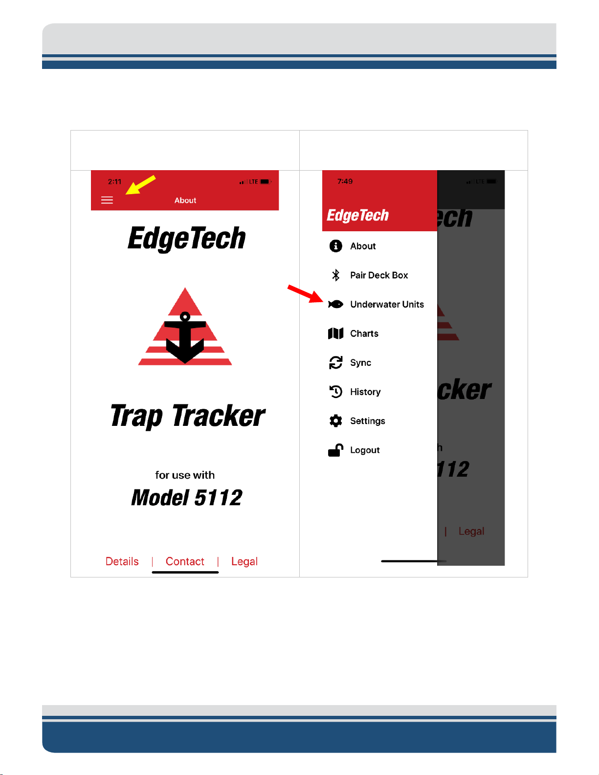
4-54 5.0 MAINTENANCE
1. Select the three-line Trap Tracker menu
2. Select Underwater Units from the left side
To do so:
button.
menu.
5112 Ropeless Fishing System 0022081_REV_A
Page 88
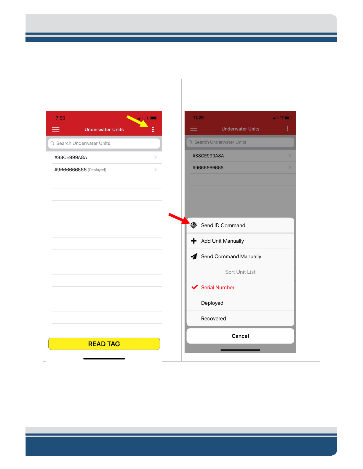
4-55
3. Select the three-dot options menu on the
4. To Send the ID Command select Send ID
that can receive the acoustic signal from a
transponder.
upper right-hand side of the Underwater Units
screen.
Command. This will return the ID of a release
Page 89

4-56 5.0 MAINTENANCE
5. To send a Command to a
specific release. Press the
Send Command Manually
Button. The Send
will appear. Select either
the ID, Status or Release
Command and enter the
corresponding Command
Code. Press send when
Command Manually popup
complete.
5112 Ropeless Fishing System 0022081_REV_A
Page 90

4-57
1. Select the three-line Trap Track Menu button
Trap Tracker
2. The Underwater Unit History screen will
by entering the first few digits in the search field.
4.3 Post Deployment
4.3.1 Trap Tracker History
Trap Tracker provides a historical log of all transactions performed by the Trap Tracker account installed
on the device. This includes deployment and recovery positions, ranges, recovery temperatures any catch
quantities or trap counts entered into operational details at recovery. This data can be exported using the
options explained in the D
every release used, even if not in the current Underwater Units list. This is useful in troubleshooting or
manually adding releases to an Underwater Unit List.
To view:
and select History from the
Menu.
ATA EXPORT section of this manual. The Unit Serial numbers provided are for
appear. A list of all the Underwater Units used
with the account will appear by serial number.
Select the line of the unit you would like to
view.
If the list is long, you can search by serial number
Page 91

4-58 5.0 MAINTENANCE
You can also select three-dot Underwater Units
Unit list by Serial Number, Deployed Units or
Recovered Units.
menu on the upper right if you’d like to sort the
5112 Ropeless Fishing System 0022081_REV_A
Page 92

4-59
3. The Unit history screen will appear that
operational data
coordinates are
lable for long
displays release deployments and recoveries
by latest date with the
collected at the time. In the case of Trap Point
or Trap Line deployments, date, time, and
deployment position
displayed. In the case of recoveries, recovery
date, time, range to the unit, date and time of
recovery command issued, temperature, userprovided catch quantities, and trap counts are
displayed. This screen is scrol
histories.
4.3.1.1 Deleting Release History
It is possible to remove the history of a single release or all releases associated with a Trap Tracker
account.
Caution- Removing the history of all units clears the data permanently.
To remove the history of a single release:
Page 93

4-60 5.0 MAINTENANCE
1. Go to History in the Track Tracker Menu
lined Trap Track
The Underwater History Screen will appear with a
by going to Underwater History Options and
sorting by Date or Serial Number.
by selecting the threeMenu Button.
listing of all saved unit histories.
You can search for a specific unit by typing the
serial number into the search field or reorder the
5112 Ropeless Fishing System 0022081_REV_A
Page 94

2. When the history to be deleted is found,
swipe left on the line. This will expose the
Clear History button that can be pressed
to delete the history of that specific unit.
4-61
To remove the histories of many or all units:
Caution- Removing the history of all units clears the data permanently.
Page 95

4-62 5.0 MAINTENANCE
1. Go to History in the Track Tracker Menu
lined Trap Track
2. The Underwater Unit History Screen will
History line.
3. The Delete History Popup will appear providing deletion options. The user can delete all data
data by selecting All and then working through the corresponding popup menu for each.
• If Date is chosen, the user can select a
entering the date and then pressing
Delete.
• If Interval is chosen, the user can select a
when done.
by selecting the threeMenu Button.
appear. Press the three-dot Underwater
History options button and then the Clear
on a specific date by selecting date, delete all data with a date interval (date range) by selecting
Interval, delete all data associated with one release with Serial Number or delete all historical
specific date to clear to all historical data
from by clicking the Select Date button,
5112 Ropeless Fishing System 0022081_REV_A
date range to clear all historical data from.
This is done by selecting and entering both
begin and end dates and pressing delete
Page 96

4-63
• If Serial # is chosen, the user can select a
when complete.
• If All is chosen, the user can delete all
historical data associated with the
specific release’s historical information to
clear by entering the serial number from
the list that appears and pressing Delete
account by selecting Delete.
Page 97

4-64 5.0 MAINTENANCE
4.3.2 Removing A Unit From The Underwater Unit List.
A release can be removed from an Underwater Unit list. Keep in mind that this list is not device-specific
but account-specific and that any change will be replicated on any other device using the Trap Tracker
account when synced.
To do so:
5112 Ropeless Fishing System 0022081_REV_A
Page 98

1. Go to the Trap Tracker Menu by selecting the
three-line menu button.
Select Underwater
2. To delete a specific unit from the Underwater Unit list left swipe its entry in the list exposing the
appears.
units when the Trap Tracker menu appears.
4-65
Delete button and press it. Confirm your deletion by selecting Delete when the Delete Unit popup
Page 99

4-66 5.0 MAINTENANCE
1. Go to History in the Trap Tracker Menu.
2. The Underwater History Screen will be
. Select Export
History for the options menu.
4.3.3 Data Export
4.3.3.1 Exporting Historical Data
Underwater Unit Historical data can be exported out of a device into CSV format. This data can then be
organized, manipulated, and presented in a spreadsheet application like Microsoft Excel or imported into
a database.
To do so:
5112 Ropeless Fishing System 0022081_REV_A
displayed. Open Underwater History Options
by pressing the three-dot menu button on the
top right side of the screen
Page 100

4-67
3. Select your application, email, or storage
destination. The choice will vary based on
flat file. A spreadsheet
application such as Microsoft Excel can be
what applications are installed on the device.
The file can then be found and manipulated
like any other CSV
used to read, edit, and create data objects.
 Loading...