

Edgetech 3200-XS Hardware Manual
i
EdgeTech
3200-XS SUB-BOTTOM SYSTEM
USER HARDWARE MANUAL
0004840_REV_E 7/2/2018
4 Little Brook Road
West Wareham, MA 02576
Tel: (508) 291-0057
Fax: (508) 291-2491
www.EdgeTech.com

ii
The information, figures, and specifications in this manual are proprietary and are issued in strict
confidence on condition that they not be copied, reprinted, or disclosed to a third party, either wholly or
in part, without the prior, written consent of EdgeTech. Any reproduction of EdgeTech supplied software
or file sharing is strictly prohibited.
Copyright © 2015 – 2018 EdgeTech. All rights reserved.
Storm Case™ is a trademark of Pelican.
Microsoft® and Windows® are registered trademarks of Microsoft Corporation.
Kevlar® is a registered trademark of the DuPont Company.
Intel® and Pentium® are registered trademarks of Intel Corporation.
Novagard G624® is a trademark of Novagard Solutions, Inc.

iii
ATTENTION – READ THIS FIRST!
All personnel involved with the installation, operation, or maintenance of the equipment described in this
manual should read and understand the warnings and cautions provided below.
CAUTION!
This equipment contains devices that are extremely sensitive to static
electricity. Therefore, extreme care should be taken when handling
them. Normal handling precautions involve the use of anti-static
protection materials and grounding straps for personnel.
WARNING!
High Voltage may be present in all parts of the system. Therefore, use
caution when the electronics are removed from their containers for
servicing.
CAUTION!
Operation with improper line voltage may cause serious damage to the
equipment. Always ensure that the proper line voltage is used.
Warnings, Cautions, and Notes
Where applicable, warnings, cautions, and notes are provided in this manual as follows:
WARNING!
Identifies a potential hazard that could cause injury or death.
CAUTION!
Identifies a potential hazard that could damage equipment or data.
NOTE: Recommendations or general information that is particular to the
material being presented.

iv
HARDWARE VARIATIONS AND COMPATIBILITY
The 3200-XS Sub-Bottom Bottom Profiling System contains both standard and proprietary hardware. At
times, EdgeTech may change the standard components due to their availability or performance
improvements. Although the component manufacturers—along with their models and styles—may
change from unit to unit, replacement parts will generally be interchangeable.
EdgeTech will make every effort to see that replacement components are interchangeable and use the
same software drivers (if applicable). At times, however, direct replacements may not exist. When this
happens, EdgeTech will provide the necessary drivers with the replacement part, if applicable.
EdgeTech may also change certain hardware per customer requirements. Therefore, portions of this
manual, such as parts lists and test features, are subject to change. These sections should be used for
reference only. When changes are made that affect system operation, they will be explicitly noted. Also,
some options and features may not be active in the customer’s unit at time of delivery. Upgrades will be
made available when these features are implemented.
Contact E
DGETECH CUSTOMER SERVICE with any questions relating to compatibility.
v
REVISION
DESCRIPTION
DATE
APPROVAL
A
Release to Production
03/09/2015
RM B Pin-out diagram updated
07/15/2015
RM C Updated drawings
08/25/2017
HS D Updates
05/01/2018
TS E Updates to Drawings
07/02/2018
TS
ABOUT THIS DOCUMENT
We, the employees at EdgeTech, would like to thank you for purchasing 3200-XS Sub-Bottom Profiling
System. At EdgeTech, it is our policy to provide high-quality, cost-effective products and support services
that meet or exceed your requirements. We also strive to deliver them on-time, and to continuously look
for ways to improve them. We take pride in the products we manufacture, and want you to be entirely
satisfied with your equipment.
Purpose of this Manual
The purpose of this manual is to provide the user with information on the setup and use of EdgeTech’s
3200-XS. Although this manual encompasses the latest operational features of the 3200-XS, some features
may be periodically upgraded. Therefore, the information in this manual is subject to change and should
be used for reference only.
Liability
EdgeTech has made every effort to document the 3200-XS in this manual accurately and completely.
However, EdgeTech assumes no liability for errors or for any damages that result from the use of this
manual or the equipment it documents. EdgeTech reserves the right to upgrade features of this
equipment, and to make changes to this manual, without notice at any time.
Revision History

vi
WARRANTY STATEMENT
All equipment manufactured by EdgeTech is warranted against defective components and workmanship
for a period of one year after shipment. Warranty repair will be done by EdgeTech free of charge.
Shipping costs are to be borne by the customer. Malfunction due to improper use is not covered in the
warranty, and EdgeTech disclaims any liability for consequential damage resulting from defects in the
performance of the equipment. No product is warranted as being fit for a particular purpose, and there is
no warranty of merchantability. This warranty applies only if:
i. The items are used solely under the operating conditions and in the manner recommended in
Seller's instruction manual, specifications, or other literature.
ii. The items have not been misused or abused in any manner, nor have repairs been attempted
thereon without the approval of EdgeTech Customer Service.
iii. Written notice of the failure within the warranty period is forwarded to Seller and the directions
received for properly identifying items returned under warranty are followed.
iv. The return notice authorizes Seller to examine and disassemble returned products to the extent
Seller deems necessary to ascertain the cause for failure.
The warranties expressed herein are exclusive. There are no other warranties, either expressed or implied,
beyond those set forth herein, and Seller does not assume any other obligation or liability in connection
with the sale or use of said products. Any product or service repaired under this warranty shall be
warranted for the remaining portion of the original warranty period only.
Equipment not manufactured by EdgeTech is supported only to the extent of the original manufacturer's
warranties.

vii
SOFTWARE SERVICE OVERVIEW
EdgeTech provides software services free of charge. This software agreement does not address customerspecified modifications or enhancements. These services may be ordered separately. Furthermore,
EdgeTech software upgrades are meant for the sole use of EdgeTech customers. Any reproduction of
EdgeTech-supplied software or file sharing is strictly prohibited.
Software Updates and Enhancements
EdgeTech customers can download new software releases with all modifications and enhancements from
the EdgeTech ftp site. Major software issues, should they occur, will be reported directly to the customer.
New software releases consist of the following:
• Software enhancements that are not on the price list
• Software fixes and changes
• Product integration
• Documentation updates to on-line help
• Tests for compatibility with other modules
Software patches consist of software that has undergone the following:
• Minor software enhancements
• Software fixes and changes
EdgeTech customers are entitled to contact E
to report a difficulty, to discuss a problem or to receive advice on the best way to perform a task. When
contacted, EdgeTech Customer Service will do the following:
• Respond within 24 hours via Telephone, Facsimile, and E-mail Support
• Immediately attend to serious problems affecting operations
• Attempt to find an immediate work-around
DGETECH CUSTOMER SERVICE by telephone, facsimile, or e-mail

viii
RETURNED MATERIAL AUTHORIZATION
Prior to returning any equipment to EdgeTech, a Returned Material
Authorization (RMA) Number must be obtained from CUSTOMER SERVICE.
RMA Purpose
The RMA Number identifies returned equipment when it arrives at our receiving dock and enables tracking
while at our facility. Refer to RMA number on all documentation and correspondences.
All returned materials must be shipped prepaid. Freight collect shipments will not be accepted. All
equipment should be adequately insured for shipping, but equipment belonging to EdgeTech must be
insured for full value.
If there is more than one item per consignment, include a packing with the shipment. An invoice can
double as a packing slip only when the contents are clearly numbered and identified on the invoice.
Shipper’s Oath:
"I, ______________________________, declare that the articles herein specified are the growth,
produce, or manufacture of the United States; that they were exported from the
United States from the port of _____________________, on or about _______________; that they
are returned without having been advanced in value or improved in condition by any
process of manufacture or any other means; and that no drawback, or allowance has
been paid or admitted hereof."
CAUTION!
Never attempt to ship a Portable Topside in its Storm CaseTM alone.
Although rugged, these cases are not intended to be used as shipping
containers and the delicate internal components could be damaged.
Shipping in this manner will void any warranties.
NOTE: All shipping charges shall be the responsibility of the customer,
unless under warranty, as EdgeTech will pay for return shipping.
NOTE: For International Shipments valued over $1000, the following
Shipper's oath must be sent with the invoice.
Signed ______________________________

ix
CUSTOMER SERVICE
Customer service personnel at EdgeTech are always eager to hear from users of our products. Your
feedback is welcome, and is a valuable source of information which we use to continually improve these
products. Therefore we encourage you to contact EdgeTech Customer Service to offer any suggestions or
to request technical support:
NOTE: Please have your system Serial Number available when contacting
Customer Service.
E-mail: service@edgetech.com
Mail: 4 Little Brook Road
West Wareham, MA 02576
Telephone: (508) 291-0057
Facsimile: (508) 291-2491
24-Hour Emergency
Technical Support Line: (508) 942-8043
For more information please go to www.EdgeTech.com
.

x
COMPANY BACKGROUND
EdgeTech (formerly EG&G Marine Instruments) traces its history in Underwater Data Acquisition and
Processing back to 1966. EdgeTech has designed, developed, and manufactured products, instruments,
and systems — for the acquisition of underwater data, including marine, estuarine, and coastal
applications — for over 50 years.
EdgeTech responds to the needs of the Scientific, Naval, and Offshore communities by providing industryleading equipment — such as Sub-Bottom Profilers, Side Scan Sonar, Acoustic Releases, USBL Positioning
Systems, and Bathymetric Systems — that have become standards in the industry.
EdgeTech consistently anticipates and responds to future needs with an active Research and Development
Program. Current efforts are focused on adapting new cutting-edge acoustic technology.

xi
TABLE OF CONTENTS
ATTENTION – READ THIS FIRST! ............................................................................................ iii
Warnings, Cautions, and Notes ................................................................................................................ iii
HARDWARE VARIATIONS AND COMPATIBILITY ..................................................................... iv
ABOUT THIS DOCUMENT ....................................................................................................... v
Purpose of this Manual ............................................................................................................................. v
Liability ...................................................................................................................................................... v
Revision History ........................................................................................................................................ v
WARRANTY STATEMENT ...................................................................................................... vi
SOFTWARE SERVICE OVERVIEW ........................................................................................... vii
Software Updates and Enhancements.................................................................................................... vii
RETURNED MATERIAL AUTHORIZATION ............................................................................... viii
RMA Purpose ......................................................................................................................................... viii
CUSTOMER SERVICE ............................................................................................................. ix
COMPANY BACKGROUND ...................................................................................................... x
TABLE OF CONTENTS ............................................................................................................ xi
LIST OF FIGURES .................................................................................................................. xiv
LIST OF TABLES .................................................................................................................... xvi
1.0: OVERVIEW ................................................................................................................... 1-1
1.1 Advantages of Full Spectrum CHIRP Technology .......................................................................... 1-1
1.1.1 Separate Acoustic Projectors and Receivers ........................................................................ 1-1
1.1.2 High Repeatability ................................................................................................................. 1-2
1.1.3 High Signal-to-Noise Ratio .................................................................................................... 1-2
1.1.4 High Resolution ..................................................................................................................... 1-2
1.1.5 Additional Processing Gain ................................................................................................... 1-2
1.1.6 Gaussian Shaped Amplitude Spectrum Outgoing Pulse ....................................................... 1-3
1.1.7 Reduction of Side Lobes ....................................................................................................... 1-3
1.2 Full Spectrum CHIRP Technology Applications ............................................................................. 1-3
1.3 Main System Components ............................................................................................................ 1-4
1.3.1 3200 Rack Mount Processor ................................................................................................. 1-4
1.3.2 SB-424, SB-216S, and SB-512i Tow Vehicles ......................................................................... 1-6

xii
1.3.3 Tow Cable ............................................................................................................................. 1-8
2.0: SPECIFICATIONS ........................................................................................................... 2-1
2.1 3200 Rack Mount Processor ......................................................................................................... 2-1
2.1.1 Rack Mount General Specifications ...................................................................................... 2-1
2.1.2 Processor Unit Specs............................................................................................................. 2-2
2.1.3 Power Amplifier .................................................................................................................... 2-2
2.1.3.1 Power Output ................................................................................................................. 2-2
2.1.3.2 Performance ................................................................................................................... 2-3
2.1.3.3 Construction ................................................................................................................... 2-3
2.1.4 Tiger Board Description ........................................................................................................ 2-3
2.1.4.1 Carrier Board .................................................................................................................. 2-4
2.1.4.2 Acquisition Board ........................................................................................................... 2-4
2.1.4.3 Sonar Board .................................................................................................................... 2-4
2.1.5 SB-424, SB-216S, and SB-512i Tow Vehicles ......................................................................... 2-6
2.2 Mechanical Drawings .................................................................................................................... 2-8
2.2.1 Kevlar Reinforced Tow Cable Specifications ....................................................................... 2-12
3.0: SETUP AND ACTIVATION .............................................................................................. 3-1
3.1 Unpacking and Inspection ............................................................................................................. 3-1
3.2 Power Requirements .................................................................................................................... 3-2
3.2.1 Use of an Uninterruptable Power Supply ............................................................................. 3-2
3.2.2 Changing to a Non-US Power Plug ........................................................................................ 3-2
3.3 Navigation Interface ..................................................................................................................... 3-2
3.4 Topside Placement ........................................................................................................................ 3-2
3.4.1 Rack Mount Controls and Indicators .................................................................................... 3-3
3.5 Rack Mount Deck Unit Connections ............................................................................................. 3-6
3.6 Connecting the System Components ............................................................................................ 3-7
3.6.1 Connecting and Attaching the Tow Cable to the Tow Vehicle ............................................. 3-7
3.6.2 Connecting the Rack Mount Topside .................................................................................... 3-9
3.7 Activating the System ................................................................................................................... 3-9
3.8 Pre-Deployment Tests................................................................................................................. 3-10
3.9 Tow Vehicle Deployment ............................................................................................................ 3-13
3.9.1 Obtaining the Best Sonar Imagery When Towing............................................................... 3-13
3.9.2 Conducting Sediment Classification Surveys When Towing ............................................... 3-14

xiii
4.0: MAINTENANCE ............................................................................................................ 4-1
4.1 Periodic Maintenance ................................................................................................................... 4-1
4.1.1 Cleaning the 3200-XS Topside Processor .............................................................................. 4-1
4.1.2 Cleaning the Tow Vehicle and Tow Cable after Use ............................................................. 4-1
4.1.3 Inspecting and Cleaning the Underwater Connectors .......................................................... 4-1
4.1.4 Storage .................................................................................................................................. 4-2
4.1.5 Restoring the Operating System ........................................................................................... 4-2
4.2 Disassembling and Reassembling a Tow Vehicle .......................................................................... 4-2
4.2.1 Disassembling a Tow Vehicle ................................................................................................ 4-3
4.2.2 Reassembling a Tow Vehicle ................................................................................................. 4-5
5.0: TROUBLESHOOTING ..................................................................................................... 5-1
5.1 Rack Mount Deck Unit Troubleshooting ....................................................................................... 5-2
5.2 Connector Pinouts ........................................................................................................................ 5-4
5.3 Wiring and Connector Pinout Drawings ....................................................................................... 5-6
A.0: SYSTEM RESTORE ..................................................................................... A-1
B.0: FAQ B-1

xiv
LIST OF FIGURES
Figure 1-1: 3200 Rack Mount Processor .................................................................................................... 1-5
Figure 1-2: Tiger and Mother Boards inside 3200-XS Topside Processor .................................................. 1-6
Figure 1-3: SB-424, SB-216S, and SB-512i Tow Vehicles ............................................................................ 1-7
Figure 1-4: 75-Meter Kevlar Reinforced Tow Cable ................................................................................... 1-8
Figure 2-1: Tiger Board Set: Carrier (Front view) – 0006013 ..................................................................... 2-5
Figure 2-2: Tiger Board Set: Carrier (Rear View) – 0006013 ...................................................................... 2-5
Figure 2-3: Tiger Board Set: Acquisition PCB - 0014231 ............................................................................ 2-6
Figure 2-4: Tiger Board Set: SIBU aka Sonar Interface Board – 0011637 .................................................. 2-6
Figure 2-5: SB-216 Towfish Outline Drawing ............................................................................................. 2-9
Figure 2-6: SB-424 Towfish Outline Drawing ........................................................................................... 2-10
Figure 2-7: SB-512i Towfish Outline Drawing .......................................................................................... 2-11
Figure 3-1: Front Panel of 3200-XS Rack Mount Topside .......................................................................... 3-4
Figure 3-2: Topside Rear Panel Controls and Connections ........................................................................ 3-5
Figure 3-3: Reinforced Cable Attached to SB-216S Tow Vehicle ............................................................... 3-8
Figure 3-4: Recommended Method for Dressing and Strain Relieving Tow Cable .................................... 3-8
Figure 3-5: The DISCOVER Sub-Bottom Main Window ............................................................................ 3-10
Figure 3-6: Successful Self-Test ................................................................................................................ 3-11
Figure 3-7: NET: ON .................................................................................................................................. 3-11
Figure 3-8: The Sub-Bottom Control Tab ................................................................................................. 3-11
Figure 3-9: Tap Test .................................................................................................................................. 3-12
Figure 4-1: Retaining Ring and Locking Sleeve Removed .......................................................................... 4-3
Figure 4-2: Male Connector ....................................................................................................................... 4-3
Figure 4-3: Removing the 7/16-Inch Bolts Securing the Teardrop Cover to the Tow Vehicle ................... 4-4
Figure 4-4: Removing the Teardrop Cover ................................................................................................. 4-4
Figure 4-5: Teardrop Cover Removed ........................................................................................................ 4-5
Figure 4-6: Removing 7/16 and ½ Inch Bolts and Nuts .............................................................................. 4-5

xv
Figure 4-7: SB-424, SB-216S and SB-512i Tow Vehicle Internals ............................................................... 4-6
Figure 5-1: SEA CABLE Connector—Female Face View .............................................................................. 5-4
Figure 5-2: Male Marshal Connector – 86-5MC (Tow Vehicle to Tow Cable Connection) ........................ 5-5
Figure 5-3: Female Marshal Connector – 86-5FC (Tow Cable to Tow Vehicle Connection) ...................... 5-5
Figure 5-4: Wiring Harness, Rack Mount Deck Unit – 0004957 ................................................................. 5-7
Figure 5-5: Wiring Diagram, Spider Box, SB-424 Tow Vehicle – 0003174 ................................................. 5-8
Figure 5-6: Wiring Diagram, SB-424 Tow Vehicle – 0016154 .................................................................... 5-9
Figure 5-7: Wiring Diagram, Spider Box, SB-216S Tow Vehicle – 0003173 ............................................. 5-10
Figure 5-8: Wiring Diagram, SB-216S Tow Vehicle – 0016153 ................................................................ 5-11
Figure 5-9: Wiring Diagram, Spider Box, SB-512i Tow Vehicle - 0003172 ............................................... 5-12
Figure 5-10: Wiring Diagram, SB-512i Tow Vehicle ................................................................................. 5-13
Figure 5-11: Wiring Diagram, 75-Meter Kevlar Reinforced Tow Cable – 002980 .................................... 5-14
Figure 5-12: Wiring Diagram, 200-Meter Kevlar Reinforced Tow Cable – 0011685 ................................ 5-15

xvi
LIST OF TABLES
Table 2-1: Rack Mount General Specifications .......................................................................................... 2-1
Table 2-2: 3200-XS Topside Processor Specs ............................................................................................. 2-2
Table 2-3: Power Amplifier Specs: Power Output ..................................................................................... 2-2
Table 2-4: Power Amplifier Specs: Performance ....................................................................................... 2-3
Table 2-5: Power Amplifier Specs: Construction ....................................................................................... 2-3
Table 2-6: Tow Vehicle Specifications ........................................................................................................ 2-7
Table 2-7: 75-Meter Kevlar Reinforced Tow Cable Specifications ........................................................... 2-12
Table 3-1: AC Power Cord Wiring .............................................................................................................. 3-2
Table 5-1: Rack Mount Troubleshooting ................................................................................................... 5-3
Table 5-2: SEA CABLE Connector Pinouts .................................................................................................. 5-4
Table 5-3: Tow Cable Connections ............................................................................................................. 5-5
Table 5-4: SEA CABLE Female Connector ................................................................................................... 5-5

1-1
1.0: OVERVIEW
The 3200-XS Sub-Bottom Profiling System is a high resolution wideband frequency modulated (FM) subbottom profiler that uses EdgeTech’s proprietary Full Spectrum CHIRP technology to generate crosssectional images of the seabed and collect digital normal incidence reflection data over many frequency
ranges. The 3200-XS transmits an FM pulse (also called "CHIRP pulse") that is linearly swept over a full
spectrum frequency range.
The reflections measured by the system are displayed as shades of gray or color on a computer monitor
and may be printed on a continuous feed thermal printer. Data are stored in real time onto a large capacity
hard drive and can be archived to DVD.
1.1 Advantages of Full Spectrum CHIRP Technology
EdgeTech's Full Spectrum CHIRP technology has several distinct advantages over conventional subbottom profiling systems: The use of separate acoustic projectors and receivers enable:
• Simultaneous transmission and reception of acoustic signals
• High repeatability of the transmitted signals to enable sediment classification
• High signal-to-noise ratio (SNR) for improved acoustic imagery
• High resolution for measurement of fine sediment layering
• Additional processing gain for energy efficiency
• Gaussian shaped amplitude spectrum of the outgoing pulse to preserve resolution with sediment
penetration
• Reduction of side lobes for minimal destructive signal scattering caused by the sediment when
profiling near the bottom
1.1.1 Separate Acoustic Projectors and Receivers
The 3200-XS Sub-Bottom Profiling System uses acoustic projectors and receivers mounted in a towed
vehicle to transmit and receive acoustic FM pulse signals. The projectors are wide band piston type
transducers, and the receivers are hydrophone arrays composed of lead zirconate titanate (PZT) crystals.
The transducers are mounted in the forward section of the tow vehicle, and the hydrophone arrays, which
are designed for profiling at ship speeds up to seven knots, are mounted aft.
The use of separate transmitting transducers and receiving hydrophone arrays preserves linearity, and
allows the simultaneous transmission and reception of the acoustic signals. The transducers and
hydrophone arrays are mounted beneath acoustic baffles, which minimize direct path, tow vehicle, and
surface reflections. A preamplifier in the tow vehicle amplifies and drives the received signals through a
tow cable to the surface.

1-2
1.1.2 High Repeatability
The FM pulses are generated by a digital-to-analog (D/A) converter with a wide dynamic range and a
transmitter with linear components. This allows the energy, amplitude, and phase characteristics of the
acoustic pulses to be precisely controlled. This precision produces high repeatability and signal definition
required for sediment classification.
The frequency range of operation is determined by the acoustic characteristics of the transmitter
transducers and receiving hydrophone arrays mounted on the tow vehicle. Each tow vehicle can transmit
acoustic pulses with different center frequencies and bandwidths.
The selection of this frequency is made by the operator while profiling to achieve the best imagery, and
the tow vehicle is selected based on the sub-bottom conditions at the survey site, along with the type of
sub-bottom features that need to be imaged. EdgeTech technical support can provide assistance in
selecting the best tow vehicle for your application.
1.1.3 High Signal-to-Noise Ratio
Full Spectrum CHIRP technology does not use a conventional matched filter (the correlation filter that is
widely used to compress FM signals) to process wide band signals. Rather it uses proprietary amplitude
and phase weighting functions for the transmitted pulse and a pulse compression filter that maximizes
the SNR of the acoustic images over a wide band of operating frequencies. These functions provide a
significant SNR improvement in the acoustic image over other pulse and CHIRP sonars with band limited
components that are limited in dynamic range.
1.1.4 High Resolution
Signals received at the surface from the hydrophone arrays in the tow vehicle pass through a softwarecontrolled, programmable, gain amplifier before being digitized with a 16-bit analog-to-digital (A/D)
converter at a sampling rate of 20, 25, 40, or 50 kHz. The FM pulse is then compressed using a digital
compression filter. This correlation process is implemented in real time with forward and inverse Fast
Fourier Transforms.
The compressed pulse has a time duration approximately equal to the inverse of the bandwidth of the FM
pulse which results in a high temporal resolution. This high resolution enables the measurement of fine
layering in the sediment, an important factor in sediment classification, as it provides a more realistic
picture of the true geologic variability of the sea floor and an accurate determination of the depositional
processes.
1.1.5 Additional Processing Gain
In addition to the resolution improvement, correlation processing achieves a signal processing gain over
the background noise. This gain is approximately ten times the log of the time-bandwidth product.
This improvement is due to the signal having a time duration longer than the inverse of the bandwidth,
thus increasing signal energy without increasing the power of the outgoing pulse. To equal the typical

1-3
performance of the full spectrum sonar pulse, conventional pulse sonar would have to operate at a peak
pulse power of 100 times greater than a full spectrum pulse with a time-bandwidth product of 100.
1.1.6 Gaussian Shaped Amplitude Spectrum Outgoing Pulse
Another important feature of Full Spectrum CHIRP technology is that the signal processing optimizes the
performance of the system. The sonar contains many components, each with a unique dynamic range and
linearity characteristic, which are frequency dependent.
In addition to this characteristic, the amplitude spectrum of the outgoing pulse is chosen to be
approximately Gaussian in shape to limit the side lobe level and temporal resolution losses due to
attenuation. As a wavelet with a Gaussian shaped spectrum is attenuated by the sediment, energy is lost
but its bandwidth is nearly preserved. Therefore, even after being attenuated by sand, the acoustic pulse
has approximately the same resolution as an unattenuated pulse.
1.1.7 Reduction of Side Lobes
Use of Full Spectrum CHIRP technology reduces the side lobes in the effective transducer aperture. The
wide bandwidth of the sweep frequency has the effect of smearing the side lobes of the transducer and
thus achieving a beam pattern with virtually no side lobes. The effective spatial beam width obtained after
processing a full spectrum 2–10 kHz signal, for example is 20 degrees measured at the -3db points.
1.2 Full Spectrum CHIRP Technology Applications
Applications of Full Spectrum CHIRP Technology used in the 3200-XS Sub-Bottom Profiling System include:
• EEZ resource development
• Imaging fluidized mud to a resolution of 8 cm
• Sediment classification
• Buried pipeline and cable location and routing
• Dredging studies for inlets
• Scour/erosion surveys in rivers and streams
• Marine geotechnical surveys
• Bridge erosion surveys
• Hazardous waste target location
• Geological surveys
• Archeological surveys
• Hazard surveys
• Mining and dredging surveys
• Bridge and shoreline scour surveys

1-4
• Imaging biologics in water column
• Mapping clam populations
• Beach re-nourishment
• Military and offshore oil applications
• Full ocean depth sub-bottom imaging (hull mount systems)
• Environmental site investigations
1.3 Main System Components
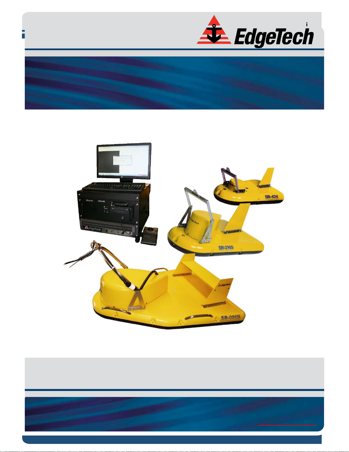
The 3200-XS Sub-Bottom Profiling System is composed of three main components: a 3200 Rack Mount
Processor; an SB-424, SB-216S or SB-512i Tow Vehicle; and a Tow Cable.
1.3.1 3200 Rack Mount Processor
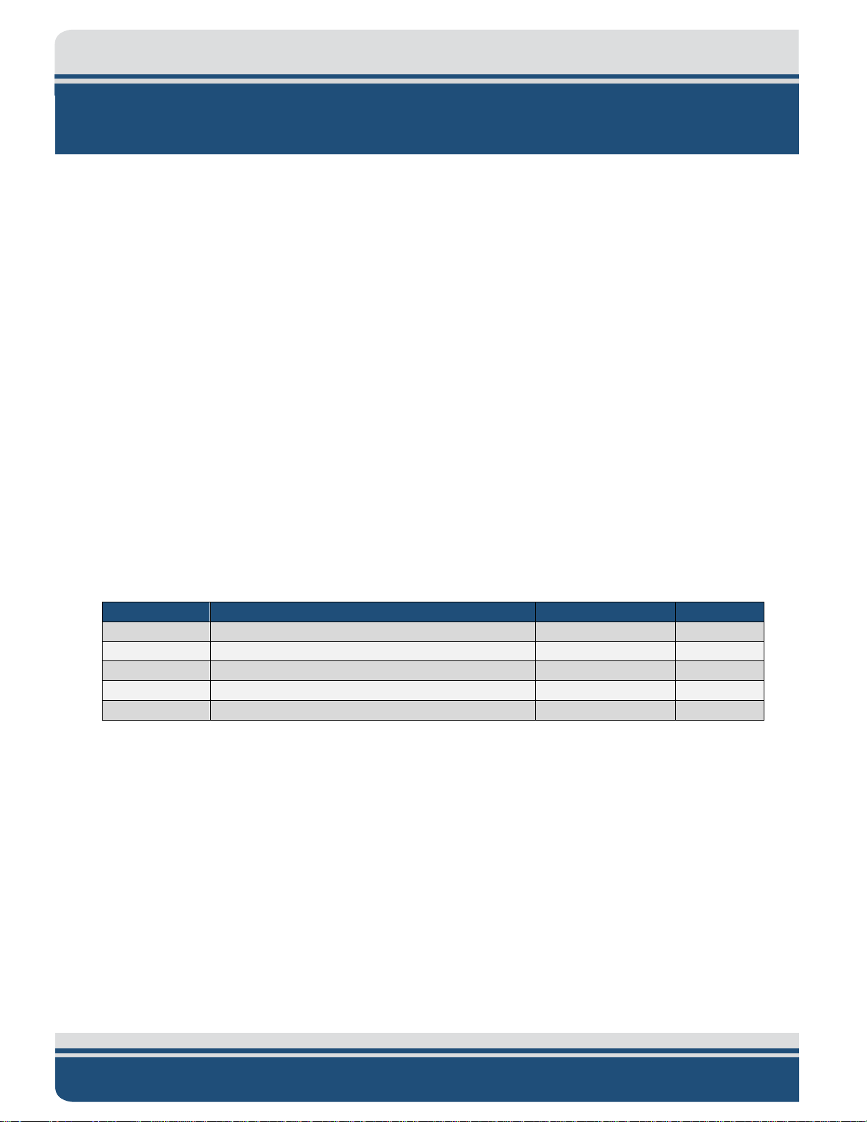
The 3200 Rack Mount processor is shown in FIGURE 1-1 and consists of a 3200-XS Topside Processor and a
4.7-kW Power Amplifier that is mounted in a portable 19-inch rack type enclosure and shipped in a heavyduty reusable transport case. The processor and the amplifier can also be removed and mounted in any
standard 19-inch rack.
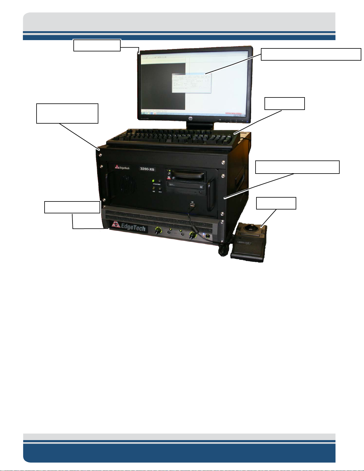
The processor includes a Mother board and a Sonar Interface board (Tiger board) as shown in F
The Tiger board interfaces to the Mother board via USB. It also includes an LCD monitor, a DVD R/W drive,
a keyboard, and a trackball.
The Tiger board stores the transmit waveform and the correlation filter as well as performs correlation
processing and spherical range correction. At periodic intervals, the Tiger board sends the transmit
waveform to a 16-bit D/A converter, which generates an analog pilot signal that is amplified by the Power
Amplifier to drive the transducer in the tow vehicle.
The acoustic returns from the sea floor are received by the hydrophone arrays in the tow vehicle and then
amplified by a preamplifier, which is also mounted in the tow vehicle. The output of the preamplifier
connects through the tow cable to a digitally-controlled amplifier on the Tiger board, and is sampled by a
16-bit A/D converter.
The Tiger board also performs the correlation processing, corrects for spherical spreading, and transfers
the data to the Mother board. For additional information on the Tiger board, refer to sub-section 2.1.4.
IGURE 1-2.
1-5
LCD Monitor
19-inch Rack
Power Amplifier
DISCOVER Sub-Bottom Software
Keyboard
Trackball
3200-XS Topside Processor
Figure 1-1: 3200 Rack Mount Processor
The 3200 Rack Mount processor also includes the EdgeTech DISCOVER 3200SB software preinstalled on
the 3200-XS Topside Processor. DISCOVER 3200SB is a data acquisition and processing program designed
exclusively for EdgeTech Full Spectrum CHIRP sonar systems. The program, which runs on the Microsoft
Windows 7 operating system, verifies that the sonar system is working properly prior to deployment by
providing data displays, diagnostics, data recording, playback, and printer outputs.
The program supports sonar data inputs, along with sonar command and control outputs over a TCP/IP
connection, a NMEA navigation input through an RS-232 serial port, and a printer connection through an
Ethernet port.
For compatibility with other EdgeTech products, DISCOVER 3200SB interfaces with a second software
program, SONAR.EXE which runs in the background and controls the sub-bottom sonar system, performs
a self-test on startup, and generates reports and diagnostic information. It automatically launches when
the processor is switched on. SONAR.EXE interfaces with the Tiger board to generate and transmit CHIRP
pulses.
1-6
Tiger Board
Mother Board
Hard Drive
Power Supply
Figure 1-2: Tiger and Mother Boards inside 3200-XS Topside Processor
1.3.2 SB-424, SB-216S, and SB-512i Tow Vehicles
The SB-424, SB-216S, and SB-512i Tow Vehicles are each designed to operate over a specific frequency
range, and as lower operating frequencies generally require longer hydrophone arrays and larger
transducers, the vehicles differ primarily in size and weight.
The SB-424 Tow Vehicle, which is the smallest of the three, operates over a frequency range of 4–24 kHz,
followed by the SB-216S at 2–16 kHz, and then the SB-512i at 0.500–12 kHz. All three tow vehicles are
shown in F
Each is hydrodynamically stable, with the transducers and hydrophone arrays mounted under an acoustic
baffle to reject downward traveling multiple echoes. These components, along with "spider" cable
harnesses and a preamplifier, are enclosed in a two-piece fiberglass shell that is fitted with stabilizing fins
and lead ballast.
A hinged U-framed tow bridle is used for towing, and the tow point location can be adjusted to
accommodate different towing speeds and depths. The tow vehicles are each shipped in a wooden crate.
IGURE 1-3.
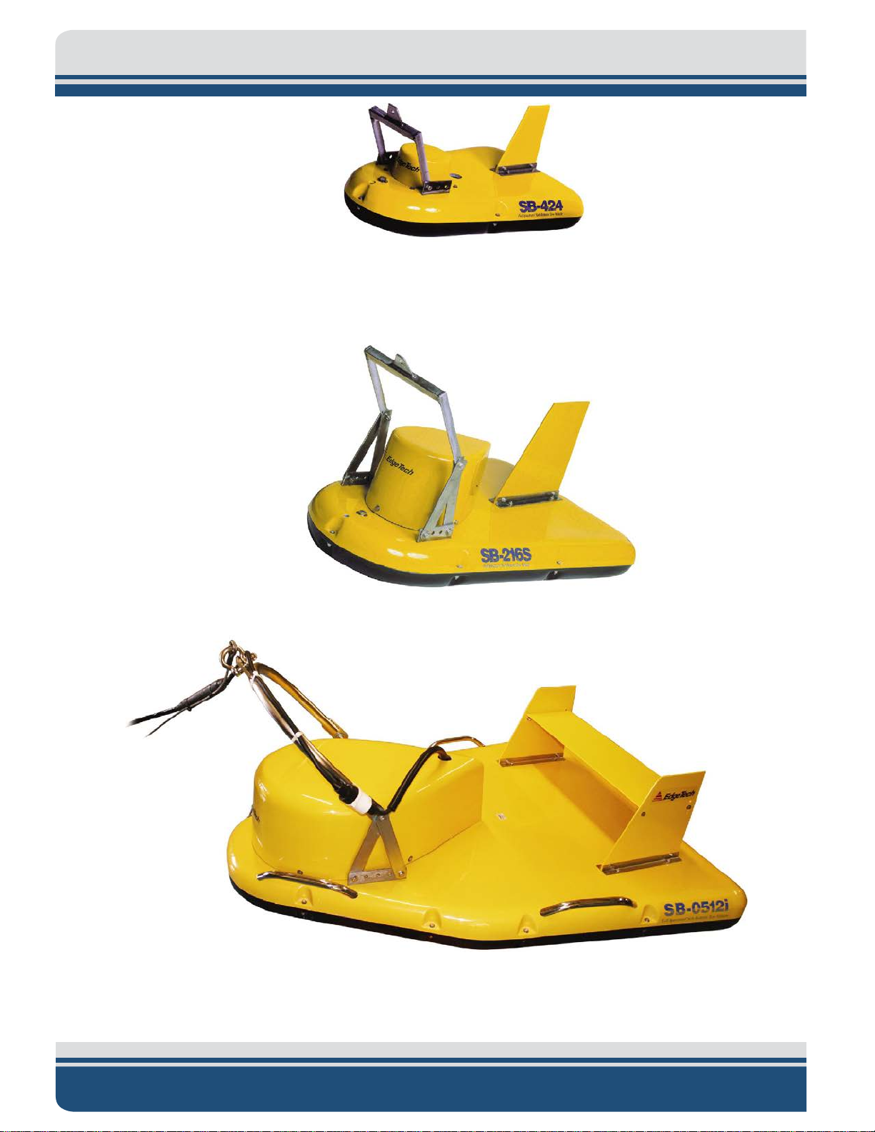
1-7
SB-424 Tow Vehicle
SB-216S Tow Vehicle
SB-512i Tow Vehicle
Figure 1-3: SB-424, SB-216S, and SB-512i Tow Vehicles
 Loading...