

Page 1
EdgeTech
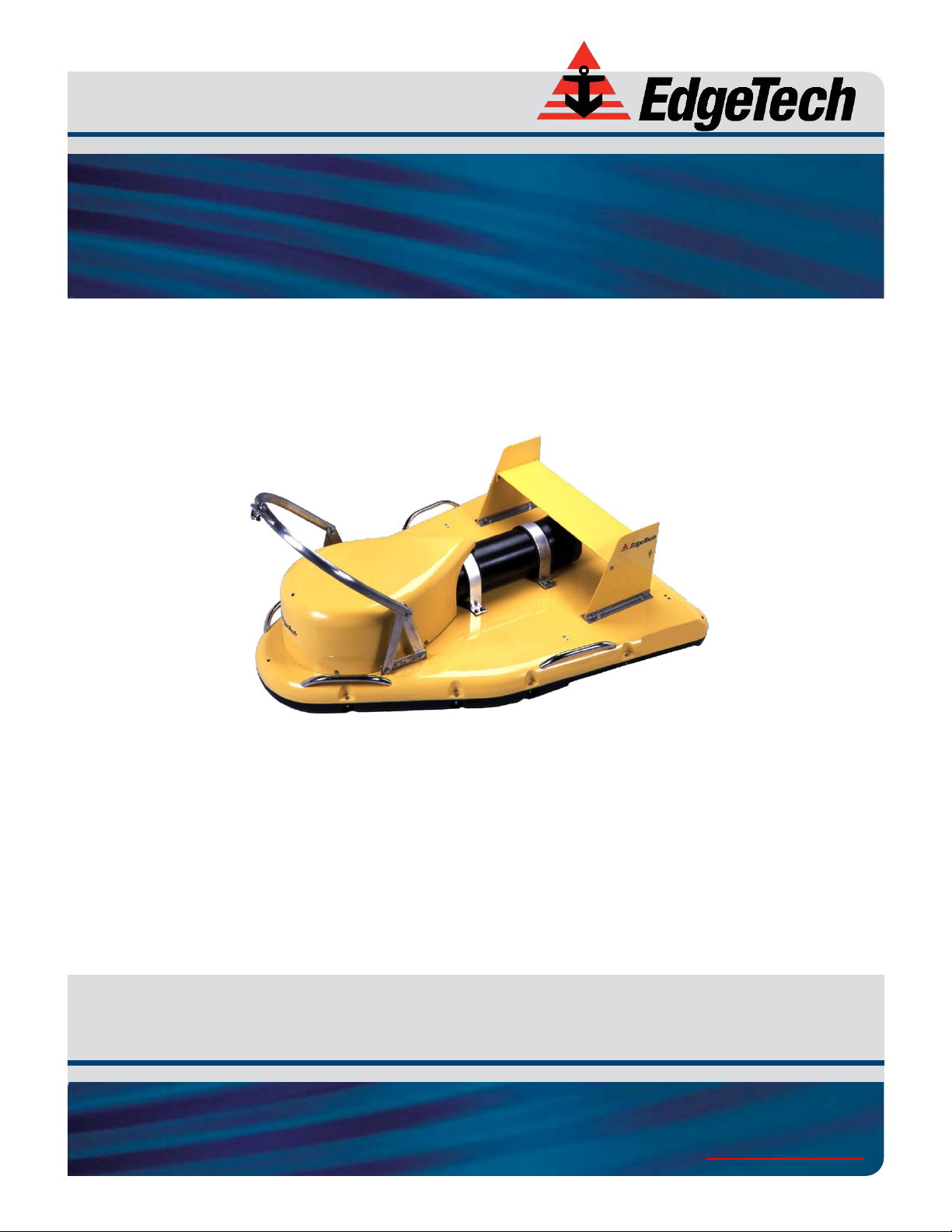
2000-CSS COMBINED SONAR
USER HARDWARE MANUAL
0017423_REV_C February 2018
4 Little Brook Road
West Wareham, MA 02576
Tel: (508) 291-0057
Fax: (508) 291-2491
www.EdgeTech.com
Page 2

ii
The information, figures, and specifications in this manual are proprietary and are issued in strict
confidence on condition that they not be copied, reprinted, or disclosed to a third party, either wholly or
in part, without the prior, written consent of EdgeTech. Any reproduction of EdgeTech supplied software
or file sharing is strictly prohibited.
EdgeTech © 2016. All rights reserved.
DISCOVER™ is a trademark of EdgeTech
G624 ® is a registered trademark of Novagard®
Windows® is a registered trademark of the Microsoft® Corporation
Core™ is a trademark of Intel®
2000-CSS COMBINED SONAR 0017423_REV_C
Page 3

iii
ATTENTION – READ THIS FIRST!
All personnel involved with the installation, operation, or maintenance of the equipment described in this
manual should read and understand the warnings and cautions provided below.
CAUTION! This equipment contains devices that are extremely sensitive
to static electricity. Therefore, extreme care should be taken when
handling them. Normal handling precautions involve the use of anti-static
protection materials and grounding straps for personnel.
WARNING! High Voltage may be present in all parts of the system.
Therefore, use caution when the electronics are removed from their
containers for servicing.
CAUTION! Operation with improper line voltage may cause serious
damage to the equipment. Always ensure that the proper line voltage is
used.
Page 4

iv
HARDWARE VARIATIONS AND COMPATIBILITY
The 2000-CSS COMBINED SONAR contains both standard and proprietary hardware. At times, EdgeTech
may change the standard components due to their availability or performance improvements. Although
the component manufacturers—along with their models and styles—may change from unit to unit,
replacement parts will generally be interchangeable.
EdgeTech will make every effort to see that replacement components are interchangeable and use the
same software drivers (if applicable). At times, however, direct replacements may not exist. When this
happens, EdgeTech will provide the necessary drivers with the replacement part, if applicable.
EdgeTech may also change certain hardware per customer requirements. Therefore, portions of this
manual, such as parts lists and test features, are subject to change. These sections should be used for
reference only. When changes are made that affect system operation, they will be explicitly noted. Also,
some options and features may not be active in the customer’s unit at time of delivery. Upgrades will be
made available when these features are implemented.
Contact E
DGETECH CUSTOMER SERVICE with any questions relating to compatibility.
2000-CSS COMBINED SONAR 0017423_REV_C
Page 5
v
REVISION
DESCRIPTION
DATE
APPROVAL
A
Release to Production
08/19/2015
TW B Updates to Manual
10/17/2016
TW C Updates to Manual
02/03/2018
TS
ABOUT THIS DOCUMENT
We, the employees at EdgeTech, would like to thank you for purchasing 2000-CSS Combined Sonar
System. At EdgeTech, it is our policy to provide high-quality, cost-effective products and support services
that meet or exceed your requirements. We also strive to deliver them on-time, and to continuously look
for ways to improve them. We take pride in the products we manufacture, and want you to be entirely
satisfied with your equipment.
Purpose of this Manual
The purpose of this manual is to provide the user with information on the setup and use of EdgeTech’s
2000-CSS. Although this manual encompasses the latest operational features of the 2000-CSS, some
features may be periodically upgraded. Therefore, the information in this manual is subject to change and
should be used for reference only.
Liability
EdgeTech has made every effort to document the 2000-CSS in this manual accurately and completely.
However, EdgeTech assumes no liability for errors or for any damages that result from the use of this
manual or the equipment it documents. EdgeTech reserves the right to upgrade features of this
equipment, and to make changes to this manual, without notice at any time.
Warnings, Cautions, and Notes
Where applicable, warnings, cautions, and notes are provided in this manual as follows:
WARNING! Identifies a potential hazard that could cause injury or death.
CAUTION! Identifies a potential hazard that could damage equipment or
data.
NOTE: Recommendations or general information that is particular to the
material being presented.
Revision History
Page 6

vi
WARRANTY STATEMENT
All equipment manufactured by EdgeTech is warranted against defective components and workmanship
for a period of one year after shipment. Warranty repair will be done by EdgeTech free of charge.
Shipping costs are to be borne by the customer. Malfunction due to improper use is not covered in the
warranty, and EdgeTech disclaims any liability for consequential damage resulting from defects in the
performance of the equipment. No product is warranted as being fit for a particular purpose, and there is
no warranty of merchantability. This warranty applies only if:
i. The items are used solely under the operating conditions and in the manner recommended in
Seller's instruction manual, specifications, or other literature.
ii. The items have not been misused or abused in any manner, nor have repairs been attempted
thereon without the approval of EdgeTech Customer Service.
iii. Written notice of the failure within the warranty period is forwarded to Seller and the directions
received for properly identifying items returned under warranty are followed.
iv. The return notice authorizes Seller to examine and disassemble returned products to the extent
Seller deems necessary to ascertain the cause for failure.
The warranties expressed herein are exclusive. There are no other warranties, either expressed or implied,
beyond those set forth herein, and Seller does not assume any other obligation or liability in connection
with the sale or use of said products. Any product or service repaired under this warranty shall be
warranted for the remaining portion of the original warranty period only.
Equipment not manufactured by EdgeTech is supported only to the extent of the original manufacturer's
warranties.
2000-CSS COMBINED SONAR 0017423_REV_C
Page 7

vii
SOFTWARE SERVICE OVERVIEW
EdgeTech provides software services free of charge. This software agreement does not address customerspecified modifications or enhancements. These services may be ordered separately. Furthermore,
EdgeTech software upgrades are meant for the sole use of EdgeTech customers. Any reproduction of
EdgeTech-supplied software or file sharing is strictly prohibited.
Software Updates and Enhancements
EdgeTech customers can download new software releases with all modifications and enhancements from
the EdgeTech ftp site. Major software issues, should they occur, will be reported directly to the customer.
New software releases consist of the following:
• Software enhancements that are not on the price list
• Software fixes and changes
• Product integration
• Documentation updates to on-line help
• Tests for compatibility with other modules
Software patches consist of software that has undergone the following:
• Minor software enhancements
• Software fixes and changes
• Software Telephone, Facsimile, and E-mail Support
EdgeTech customers are entitled to contact EdgeTech Customer Service by telephone, facsimile, or e-mail
to report a difficulty, to discuss a problem or to receive advice on the best way to perform a task. When
contacted, EdgeTech Customer Service will do the following:
• Respond within 24 hours
• Immediately attend to serious problems affecting operations
• Attempt to find an immediate work-around
Page 8

viii
RETURNED MATERIAL AUTHORIZATION
Prior to returning any equipment to EdgeTech, a Returned Material Authorization (RMA) number must be
obtained. The RMA will help us identify your equipment when it arrives at our receiving dock and track
the equipment while it is at our facility. The material should be shipped to the address provided in the
E
DGETECH CUSTOMER SERVICE section. Please refer to the RMA number on all documents and
correspondences as well.
All returned materials must be shipped prepaid. Freight collect shipments will not be accepted. EdgeTech
will pay freight charges on materials going back to the customer after they have been evaluated and/or
repaired.
The following steps apply only to material being returned from outside the Continental United States.
Follow them carefully to prevent delays and additional costs.
1. All shipments must be accompanied by three copies of your proforma invoice, showing the value
of the material and the reason for its return. If the reason is for repair, it must be clearly stated in
order to move through customs quickly and without duties being charged. Whenever possible,
please send copies of original export shipping documents with the consignment.
2. If the value of the equipment is over $1000, the following Shipper's oath must be sent with the
invoice. This oath can be typed on the invoice, or on a separate letterhead:
"I, ______________________________, declare that the articles herein specified are the
growth, produce, or manufacture of the United States; that they were exported from the
United States from the port of _____________________, on or about _______________;
that they are returned without having been advanced in value or improved in condition
by any process of manufacture or any other means; and that no drawback, or allowance
has been paid or admitted hereof."
Signed ______________________________
3. If there is more than one item per consignment, a packing list must accompany the shipment. It
is acceptable to combine the proforma invoice and packing list as long as the contents of each
carton are clearly numbered and identified on the invoice.
4. Small items can be shipped prepaid directly to EdgeTech by FedEx, DHL, UPS, Airborne, etc.
5. If the equipment is the property of EdgeTech (formerly EG&G Marine Instruments Division),
please insure for full value.
6. Fax one invoice, packing list, and a copy of the airway bill to EdgeTech upon shipment.
2000-CSS COMBINED SONAR 0017423_REV_C
Page 9

ix
CUSTOMER SERVICE
Customer service personnel at EdgeTech are always eager to hear from users of our products. Your
feedback is welcome, and is a valuable source of information which we use to continually improve these
products. Therefore, we encourage you to contact EdgeTech Customer Service to offer any suggestions
or to request technical support:
NOTE: Please have your system Serial Number available when contacting
Customer Service.
E-mail: service@edgetech.com
Mail: 4 Little Brook Road
West Wareham, MA 02576
Telephone: (508) 291-0057
Facsimile: (508) 291-2491
24-Hour Emergency
Technical Support Line: (508) 942-8043
For more information please go to www.EdgeTech.com
.
Page 10

x
COMPANY BACKGROUND
EdgeTech (formerly EG&G Marine Instruments) traces its history in underwater data acquisition and
processing back to 1966. EdgeTech has designed, developed, and manufactured products, instruments,
and systems—for the acquisition of underwater data, including marine, estuarine, and coastal
applications—for over 45 years.
The company has responded to the needs of the scientific, Naval, and offshore communities by providing
equipment—such as sub-bottom profilers, side scan sonar, acoustic releases, USBL positioning systems,
and bathymetric systems—that have become standards in the industry.
EdgeTech has also consistently anticipated and responded to future needs through an active research and
development program. Current efforts are focused on the application of cutting-edge CHIRP and acoustic
technology.
2000-CSS COMBINED SONAR 0017423_REV_C
Page 11

xi
TABLE OF CONTENTS
ATTENTION – READ THIS FIRST! ......................................................................................................... iii
HARDWARE VARIATIONS AND COMPATIBILITY .................................................................................. iv
ABOUT THIS DOCUMENT .................................................................................................................... v
Purpose of this Manual ............................................................................................................................. v
Liability ...................................................................................................................................................... v
Warnings, Cautions, and Notes ................................................................................................................. v
WARRANTY STATEMENT ................................................................................................................... vi
SOFTWARE SERVICE OVERVIEW ........................................................................................................ vii
Software Updates and Enhancements.................................................................................................... vii
RETURNED MATERIAL AUTHORIZATION .......................................................................................... viii
CUSTOMER SERVICE .......................................................................................................................... ix
COMPANY BACKGROUND .................................................................................................................. x
TABLE OF CONTENTS ......................................................................................................................... xi
LIST OF FIGURES IN DOCUMENT ...................................................................................................... xiv
LIST OF TABLES IN DOCUMENT ........................................................................................................ xvi
1.0: OVERVIEW 1-1
1.1 2000-CSS Applications .................................................................................................................. 1-1
1.2 Main System Components ............................................................................................................ 1-2
1.2.1 Topside Computer .................................................................................................................. 1-2
1.2.2 STARMUX III ............................................................................................................................ 1-2
1.2.3 2000-CSS Towfish ................................................................................................................... 1-3
1.2.4 Tow Cables ............................................................................................................................. 1-6
1.3 Optional Equipment ...................................................................................................................... 1-6
1.3.1 Magnetometer ....................................................................................................................... 1-6
1.3.2 Pressure Sensor ...................................................................................................................... 1-7
1.3.3 Power Loss Pinger .................................................................................................................. 1-7
1.3.4 Responder .............................................................................................................................. 1-7
1.4 Full Spectrum Chirp Technology Overview ................................................................................... 1-7
1.4.1 Separate Sub-Bottom Acoustic Projectors and Receivers ...................................................... 1-7
Page 12

xii
1.4.2 High Signal-to-Noise Ratio ...................................................................................................... 1-8
1.4.3 High Repeatability .................................................................................................................. 1-8
1.4.4 High Resolution ...................................................................................................................... 1-8
1.4.5 Reduction of Side Lobes ......................................................................................................... 1-8
1.4.6 Additional Processing Gain ..................................................................................................... 1-9
1.4.7 Gaussian Shaped Amplitude Spectrum Outgoing Pulse ......................................................... 1-9
2.0: SPECIFICATIONS .......................................................................................................................2-1
2.1 Topside Computer ........................................................................................................................ 2-1
2.2 STARMUX III Digital Telemetry Link .............................................................................................. 2-3
2.3 2000-CSS Towfish .......................................................................................................................... 2-4
3.0: SETUP AND ACTIVATION ...........................................................................................................3-1
3.1 Unpacking and Inspection ............................................................................................................. 3-1
3.2 Power Requirements .................................................................................................................... 3-2
3.2.1 Use of an Uninterruptable Power Supply............................................................................... 3-2
3.2.2 Changing to a Non-US Power Plug ......................................................................................... 3-2
3.3 Navigation Interface ..................................................................................................................... 3-2
3.4 Topside Location—Best Practices ................................................................................................. 3-3
3.5 Topside Connections, Controls, and Indicators ............................................................................ 3-3
3.5.1 Topside Computer Connections ............................................................................................. 3-3
3.5.2 Topside Computer Controls and Indicators ........................................................................... 3-4
3.5.3 STARMUX III Digital Telemetry Link Connections ................................................................... 3-7
3.5.4 STARMUX III Digital Telemetry Link Controls and Indicators ................................................. 3-7
3.6 TCP/IP Address Settings ................................................................................................................ 3-8
3.7 Connecting the System Components ............................................................................................ 3-8
3.7.1 Connecting and Attaching the Tow Cable to the Towfish ...................................................... 3-9
3.7.2 Connecting the 2000 Topside computer .............................................................................. 3-10
3.8 System Activation and Test ......................................................................................................... 3-10
3.8.1 Activating the System ........................................................................................................... 3-11
3.8.2 Performing the Pre-deployment Checks .............................................................................. 3-13
3.9 Towfish Deployment ................................................................................................................... 3-16
3.10 Towfish Recovery ........................................................................................................................ 3-17
2000-CSS COMBINED SONAR 0017423_REV_C
Page 13

xiii
4.0: TECHNICAL DESCRIPTION ..........................................................................................................4-1
4.1 2000 Topside computer ................................................................................................................ 4-1
4.1.1 Topside Computer .................................................................................................................. 4-1
4.1.2 STARMUX III Digital Telemetry Link ........................................................................................ 4-3
4.1.2.1 Selecting Negative Edge Triggering for the Optional Responder .................................... 4-4
4.2 Towfish .......................................................................................................................................... 4-8
4.3 Cables .......................................................................................................................................... 4-13
5.0: MAINTENANCE .........................................................................................................................5-1
5.1 Periodic Maintenance ................................................................................................................... 5-1
5.1.1 Inspecting and Cleaning the Towfish and Tow Cable after Use ............................................. 5-1
5.1.2 Inspecting and Cleaning the Underwater Connectors ........................................................... 5-1
5.1.3 Storage ................................................................................................................................... 5-2
5.1.4 Recommended Spares ............................................................................................................ 5-2
5.2 Restoring the Operating System to the Hard Drive ...................................................................... 5-2
5.3 Disassembling and Reassembling the Towfish ............................................................................. 5-2
5.3.1 Disassembling the Towfish ..................................................................................................... 5-3
5.3.2 Reassembling the Towfish ...................................................................................................... 5-4
5.4 Calibrating the Compass ............................................................................................................... 5-4
5.4.1 Changing the Angle of Declination ....................................................................................... 5-12
6.0: TROUBLESHOOTING .................................................................................................................6-1
6.1 2000 Topside computer Troubleshooting Guide .......................................................................... 6-1
6.2 STARMUX III Digital Telemetry Link Troubleshooting Guide ........................................................ 6-3
6.3 Towfish Troubleshooting Guide .................................................................................................... 6-5
6.3.1 Equipment Required............................................................................................................... 6-6
6.3.2 Transmission Verification ....................................................................................................... 6-6
6.3.3 Sonar Processor and Data Link ............................................................................................... 6-6
6.3.4 Topside Power Unit ................................................................................................................ 6-7
6.3.5 Command and Data Link ........................................................................................................ 6-7
6.3.6 Data link .................................................................................................................................. 6-7
6.3.7 Towfish ................................................................................................................................... 6-8
6.3.7.1 Preliminary ....................................................................................................................... 6-9
Page 14

xiv
6.3.7.2 No Sonar Data .................................................................................................................. 6-9
6.3.7.3 Power Supplies ................................................................................................................. 6-9
6.3.7.4 Test Lights ...................................................................................................................... 6-10
6.3.7.5 DDC Test points .............................................................................................................. 6-11
6.3.7.6 Modem Board Test Points ............................................................................................. 6-11
6.3.7.7 Other Checks .................................................................................................................. 6-11
6.3.8 Tow Cables ........................................................................................................................... 6-11
6.3.8.1 Shorted Wire .................................................................................................................. 6-11
6.3.8.2 Open Wire ...................................................................................................................... 6-12
6.3.8.3 Insulation Resistance Breakdown .................................................................................. 6-12
6.3.8.4 Damaged Tow cable Connector ..................................................................................... 6-13
6.4 Part Numbers for Major Topside Components .......................................................................... 6-13
6.5 Part Numbers for Major 2000-CSS Towfish Components .......................................................... 6-14
A.0: SYSTEM RESTORE ................................................................................................................. A-1
B.0: PRINTERS B-1
LIST OF FIGURES IN DOCUMENT
Figure 1-1: Rackmount Topside and Components ..................................................................................... 1-3
Figure 1-2: Towfish Parts ........................................................................................................................... 1-5
Figure 1-3: Kevlar Reinforced Tow Cable ................................................................................................... 1-6
Figure 3-1: Rack Mount Topside Front Panel ............................................................................................. 3-5
Figure 3-2: Rack Mount Topside Back Panel .............................................................................................. 3-6
Figure 3-3: System Cables .......................................................................................................................... 3-9
Figure 3-4: DISCOVER 2000-C Dual Frequency Side Scan and DISCOVER Sub-Bottom Windows ........... 3-12
Figure 3-5: Lower Control Panel, Transmit Tab—DISCOVER 2000-C Dual Frequency Side Scan ............. 3-13
Figure 3-6: Options Dialog Box, Sonar Control Tab—DISCOVER Sub-Bottom ......................................... 3-14
Figure 3-7: Options Dialog Box, Display Tab—DISCOVER Sub-Bottom .................................................... 3-15
Figure 3-8: Lower Control Panel, Bottom Track Tab—DISCOVER 2000-C ............................................... 3-17
Figure 4-1: Topside Computer Internal Components ................................................................................ 4-2
Figure 4-2: Location of Jumper JP6 on the Power Board in the FSIU STARMUX III ................................... 4-4
2000-CSS COMBINED SONAR 0017423_REV_C
Page 15

xv
Figure 4-3: STARMUX III—Internal Components ....................................................................................... 4-5
Figure 4-4: STARMUX III—Block Diagram .................................................................................................. 4-6
Figure 4-5: STARMUX III—Wiring Diagram ................................................................................................ 4-7
Figure 4-6: Towfish—Electronics Chassis ................................................................................................. 4-11
Figure 4-7: Towfish—Block Diagram ........................................................................................................ 4-12
Figure 4-8: Armored Cable, PMI Grip, Unterminated Topside ................................................................ 4-14
Figure 4-9: Test Cable .............................................................................................................................. 4-15
Figure 5-1: 2000-CSS Towfish with Teardrop Cover Removed ............................................................... 5-3
Figure 5-2: Electronics Bottle Connector End Cap .................................................................................... 5-3
Figure 6-9: Remote Desktop Icon .............................................................................................................. 5-4
Figure 6-10: Remote Desktop Splash Screen ............................................................................................. 5-5
Figure 6-11: Remote Desktop Warning Screen .......................................................................................... 5-5
Figure 6-12: Closing Sonar.exe ................................................................................................................... 5-6
Figure 6-13: Tera Term Icon ....................................................................................................................... 5-6
Figure 6-14: Tera Term Splash Screen ....................................................................................................... 5-7
Figure 6-15. Terra Term Port Set-up .......................................................................................................... 5-8
Figure 6-16. Motion Sensor Serial Output ................................................................................................. 5-8
Figure 6-17. Motion Sensor Calibration Result .......................................................................................... 5-9
Figure 6-18. Motion Sensor Serial Output .............................................................................................. 5-10
Figure 6-19: Tilt 0 degrees ....................................................................................................................... 5-10
Figure 6-20: Tilt -90 degrees .................................................................................................................... 5-10
Figure 6-21: Tilt +90 degrees ................................................................................................................... 5-11
Figure 6-22: Compass Calibration Table .................................................................................................. 5-11
Figure 6-23 ............................................................................................................................................... 5-12
Figure 6-24 ............................................................................................................................................... 5-13
Figure 6-25: Magnetic Declination Estimated Value Screen .................................................................... 5-14
Figure 6-26: Angle of Declination Calculated ........................................................................................... 5-15
Figure 6-27 ............................................................................................................................................... 5-16
Figure 6-1: SockBlast Window ................................................................................................................... 6-8
Page 16

xvi
LIST OF TABLES IN DOCUMENT
Table 2-1: Topside Computer Specifications ............................................................................................. 2-2
Table 2-2: STARMUX III Digital Telemetry Link Specifications ................................................................... 2-3
Table 2-3: Tow Fish Specifications ............................................................................................................. 2-6
Table 3-1: AC Power Cord Wiring .............................................................................................................. 3-2
Table 3-2: STARMUX III Devices TCP/IP Addresses .................................................................................... 3-8
Table 3-3: Towfish Ethernet Devices IP Addresses .................................................................................... 3-8
Table 6-1: 2000 Topside computer—Troubleshooting Guide ................................................................... 6-3
Table 6-2: STARMUX III Digital Telemetry Link—Troubleshooting Guide.................................................. 6-5
Table 6-3: Main Voltage Test Points on Tow Fish Power Distribution Board .......................................... 6-10
Table 6-4: Other Voltages on SSB Board .................................................................................................. 6-10
Table 6-5: Major Topside Components and Part Numbers ..................................................................... 6-13
Table 6-6: Major 2000-CSS Towfish Components and Part Numbers ..................................................... 6-14
Table B-1: Printer Requirements ............................................................................................................... B-1
2000-CSS COMBINED SONAR 0017423_REV_C
Page 17

1-1
1.0: OVERVIEW
The EdgeTech 2000-CSS combined series sonar system combines EdgeTech’s world leading side scan sonar
and sub-bottom profiling technologies into a single package. The system uses five channels (four side scan
and one for sub-bottom) to transmit simultaneously frequency modulated (FM) pulses.
The 2000-CSS uses EdgeTech’s proprietary Full Spectrum CHIRP technologies to simultaneously generate
both high-resolution side scan imagery at longer ranges conventional continuous (CW) systems, along
with high-resolution cross sectional images of the seabed at deeper penetrations than CW systems can
achieve.
The system comes available with a choice of two dual-frequency configurations for the side scan sonar:
100/400 kHz or 300/600 kHz, and uses a low frequency, 500–12 kHz sub-bottom sonar for greater bottom
penetration in water depths up to 300 meters.
Side scan frequencies and the sub bottom frequency are transmitted simultaneously as linearly-swept,
wide band, high-energy acoustic pulses (also called CHIRP pulses) over a full spectrum frequency range.
The received echoes are processed into high signal-to-noise (SNR) images which can be directly displayed
as shades of gray or color on a computer monitor and printed on a continuous feed thermal printer. The
data can also be stored in real time onto a large capacity hard drive and archived onto a DVD.
A standard 2000-CSS system comes complete with a towfish, digital telemetry that runs over a single
coaxial cable up to 6,000 meters long, and a 19-inch rack mount topside running EdgeTech’s DISCOVER
acquisition software. Additionally, the 2000-CSS can be integrated with a number of auxiliary sensors to
track depth, altitude, and magnetrometry. The system can able be equipped with a USBL responder.
1.1 2000-CSS Applications
Applications for the 2000-CSS Combined side scan sonar and sub-bottom profiling system include:
• Archeological surveys
• Geological/geophysical surveys
• Sediment classification
• Buried cable and pipeline surveys
• Dredging and coastal studies
• Pre/post dredging surveys
• Scour/erosion investigation
• Marine construction surveys
Page 18

1-2 1.0: OVERVIEW
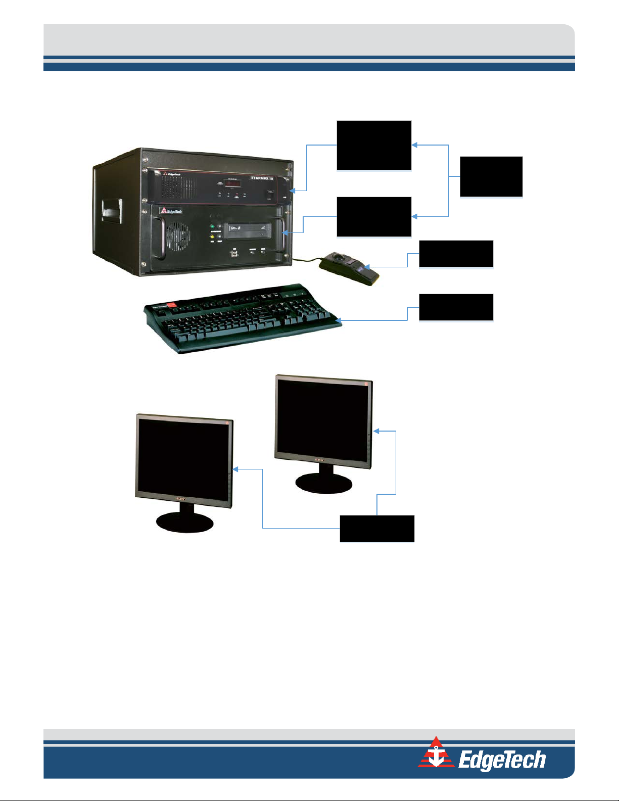
1.2 Main System Components
The 2000-CSS system is composed of two main components: a 2000 rack mount topside and a 2000-CSS
towfish. The rack mount topside includes a computer and a STARMUX III digital telemetry link installed in
a 19-inch rack enclosure, along with a keyboard, a trackball, and two LCD monitors. These components
are shown in
up to 6,000 meters in length. (Contact E
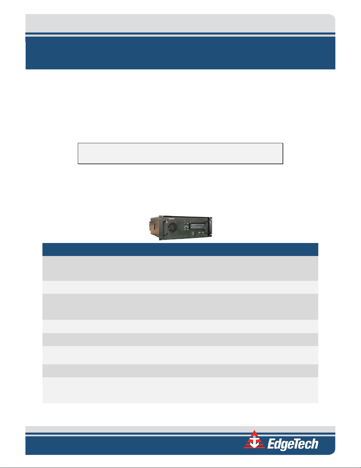
1.2.1 Topside Computer
The topside computer is a PC contained within a ruggedized 19-inch 4U chassis. It controls the towfish's
sonars and processes, stores, and displays received side scan and sub-bottom data, as well as sensor data
and status information. A keyboard, a trackball, two LCD monitors, a DVD/RW drive, a 1-TB hard drive for
data storage, and a 500-GB hard drive for the operating system are included with the topside computer.
The computer can also interface with a user-provided printer (see B.0:
The topside computer interfaces with the STARMUX III over a 10/100/1000BaseT Ethernet connection,
and includes EdgeTech’s DISCOVER 2000-C Dual Frequency Side Scan Sonar software and DISCOVER Sub
Bottom software preinstalled, along with the Windows 7 operating system.
FIGURE 1-1. The 2000-CSS towfish is shown in FIGURE 1-2. Optionally included is a tow cable
DGETECH CUSTOMER SERVICE for cable type versus length).
PRINTERS).
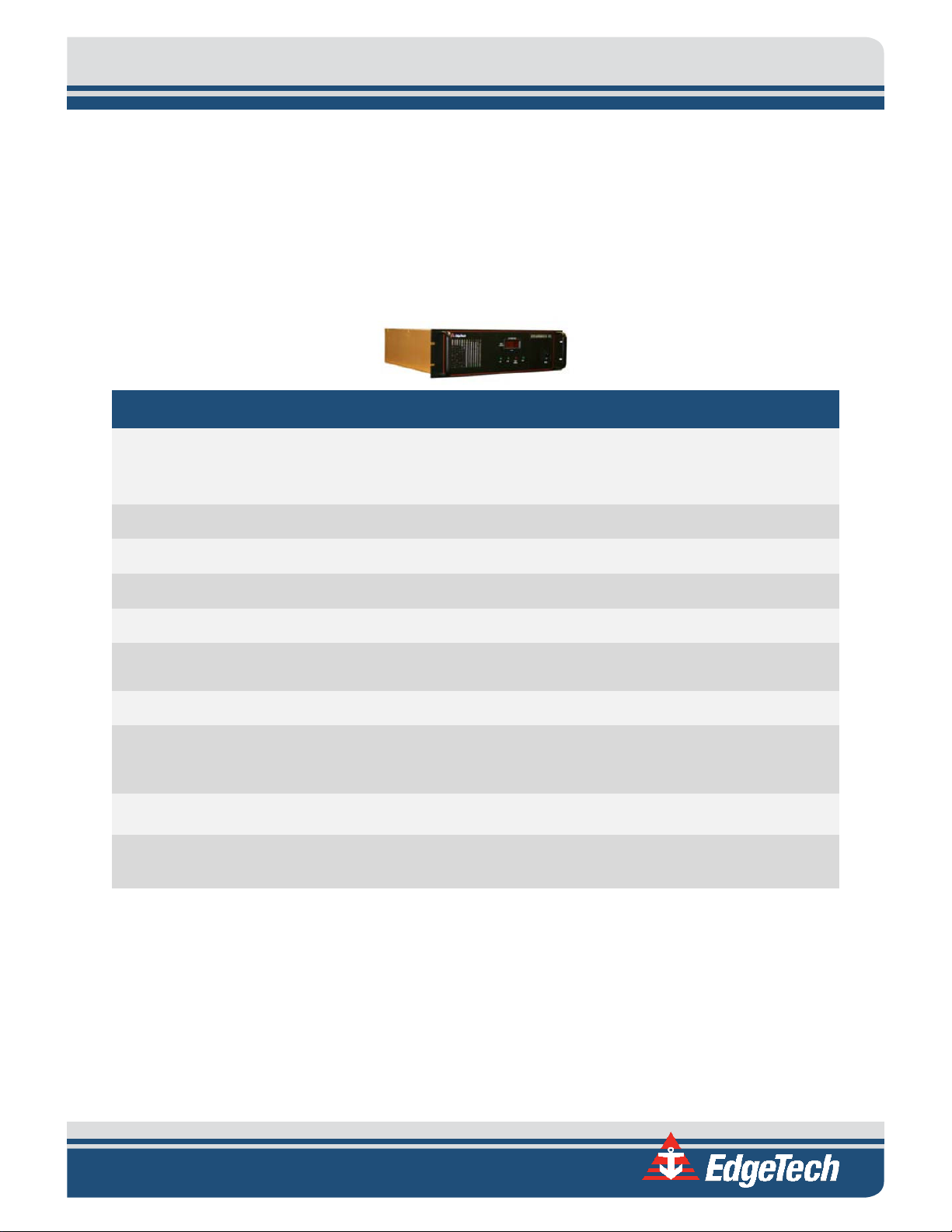
1.2.2 STARMUX III
The STARMUX III digital link provides power for the towfish, while acting as an interface between the
topside computer and the towfish. The STARMUX III provides downlink telemetry to the towfish for sonar
control and receives uplink side scan and sub bottom data, sensor data, and status information from the
towfish. Interfacing with the topside computer over a 10/100/1000BaseT Ethernet connection, the
STARMUX III includes both towfish and DC power supplies, an asynchronous digital subscriber line (ADSL)
modem, and an Ethernet switch, all within a single 19-inch 2U chassis.
2000-CSS COMBINED SONAR 0017423_REV_C
Page 19
1-3
Rack Mount
Topside
STARMUX III
Digital
Telemetry Link
2000 Topside
Computer
Keyboard
Trackball
LCD Monitors
Figure 1-1: Rackmount Topside and Components
1.2.3 2000-CSS Towfish
The 2000-CSS Towfish contains the side scan transducer arrays, the sub bottom transducer, and the subbottom hydrophone arrays, along with the electronics required to transmit and to receive the sonar
signals, to receive the downlink commands from the topside computer and to provide the uplink side scan
data, sensor data and status information to the topside computer.
Page 20
1-4 1.0: OVERVIEW
The towfish is available with a choice of 100/400 kHz or 300/600 kHz dual and simultaneous FM chirp
operating frequencies for the side scan sonar. The sonar electronics are contained inside a single
electronics bottle which includes a double O-ring sealed end cap on each end. The aft end cap contains
bulkhead connectors for connecting the transducers, the hydrophone arrays and optional equipment. The
towfish interfaces with the 2000 Topside computer over an Ethernet connection using digital subscriber
line (ADSL) modems in both the towfish and the processor.
The 2000-CSS towfish sub-bottom sonar operates over a frequency range of 0.5–12 kHz, has a 300-meter
depth rating and is designed primarily for coastal applications requiring greater bottom penetration. It is
hydro-dynamically stabilized and includes the sub-bottom transducer and four sub bottom hydrophone
arrays mounted under an acoustic baffle. This assembly, along with the connecting cable harnesses, is
contained inside a two-piece fiberglass shell which bolts together and includes tail fins and carrying
handles.
CAUTION! The carrying handles on the 2000-CSS towfish should not be
used for overhead lifting.
The port and starboard side scan transducers are mounted to the lower half of the shell. A teardrop cover
encloses the top of the sub bottom transducer and its transformer, and a hinged tow bridle provides the
mechanical connection for the tow cable. The electronics bottle is mounted to the upper half of the shell
aft of the teardrop cover.
A labeled image of the 2000-CSS towfish is shown in F
IGURE 1-2.
2000-CSS COMBINED SONAR 0017423_REV_C
Page 21
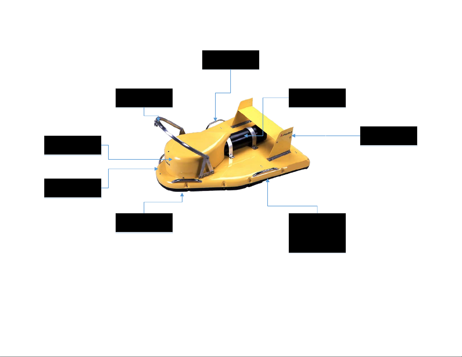
Tow Bridle
Teardrop Cover
Upper Fiberglass
Shell
Lower Fiberglass
Shell
Carrying Handles (4)
Electronics Bottle
Tail Fins
Side Scan
Transducer
(one port, one
starboard)
Figure 1-2: Towfish Parts
Page 22
1-6 1.0: OVERVIEW
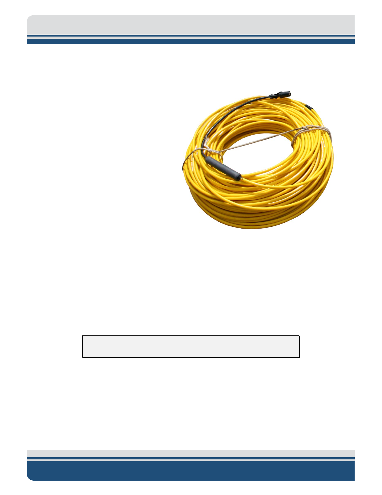
1.2.4 Tow Cables
Both Kevlar reinforced and armored tow
cables are available separately, terminated at
both ends, or just at the towfish end. The tow
cables are used to connect to and tow the
towfish. A Kevlar reinforced tow cable is
shown F
single conductor and a shield. They also
include an MCIL6F female wet pluggable
connector on the towfish end. At the topside
end, the Kevlar reinforced tow cables include
an MCIL4M connector for connecting to the
STARMUX III. The armored tow cables include
either an MCIL4M male wet-pluggable
connector or an open termination for
connection to the slip rings of a winch. A cable
grip is also included for attaching the tow
cable to the tow bridle of the towfish.
IGURE 1-3. Both cable types include a
Figure 1-3: Kevlar Reinforced Tow Cable
1.3 Optional Equipment
Optional equipment that can be installed and used with a 2000-CSS system include the following:
• Magnetometer
• Pressure sensor
• Power loss pinger
• Responder
NOTE: The option connector provides 27 VDC @ 1 A maximum.
1.3.1 Magnetometer
A magnetometer can be user specified or supplied and is available from a number of manufacturers.
2000-CSS COMBINED SONAR 0017423_REV_C
Page 23

1-7
1.3.2 Pressure Sensor
A pressure sensor can be installed in the towfish to provide towfish depth data. This type of pressure
sensor is designed for continuous use in a corrosive liquid environment and has a 500-psi pressure range.
1.3.3 Power Loss Pinger
A power loss pinger activates when towfish power is lost and the towfish is submerged. Should this event
occur, the pinger will continuously transmit an acoustic pulse which can be received by a pinger locator.
The pinger is fully self-contained in a stainless steel or aluminum housing and includes an internal battery.
1.3.4 Responder
The responder functions with an optional acoustic tracking system to provide towfish positioning. The
tracking system deck unit provides a trigger which is input to the topside computer, and the topside
computer outputs the trigger signal to the towfish by combining the signal with the downlink command
and uplink sonar data signals.
1.4 Full Spectrum Chirp Technology Overview
EdgeTech's Full Spectrum Chirp technology has several distinct advantages over conventional side scan
and sub-bottom profiling systems. These benefits include the use of separate sub-bottom acoustic
projectors and receivers to enable simultaneous transmission and reception of acoustic signals, high
signal-to-noise ratio (SNR) for improved side scan and sub-bottom imagery, high repeatability of the
transmitted signals from pulse to pulse for high signal definition, high resolution for measurement of fine
sediment layering and display of along track and across track imagery, reduction of side lobes for minimal
reception of undesired echoes, additional processing gain for energy efficiency, and a Gaussian shaped
amplitude spectrum of the outgoing pulse to preserve resolution and bandwidth with attenuation.
1.4.1 Separate Sub-Bottom Acoustic Projectors and Receivers
The side scan sonar uses a line array of piezoelectric elements to both transmit and receive the acoustic
signals, one on the port side of the towfish and one on the starboard side. The sub-bottom sonar uses
separate acoustic projectors and receivers. The projectors are wide band piston type transducers, and the
receivers are hydrophone arrays composed of lead zirconate titanate (PZT) crystals. The transducers are
mounted in the forward section of the towfish, and the hydrophone arrays are mounted aft. The use of
separate transmitting transducers and receiving hydrophone arrays preserves linearity and allows the
simultaneous transmission and reception of the acoustic signals. The transducers and hydrophone arrays
are mounted beneath acoustic baffles which minimize direct path, towfish and surface reflections.
Page 24

1-8 1.0: OVERVIEW
1.4.2 High Signal-to-Noise Ratio
Full Spectrum Chirp technology does not use a conventional matched filter, the correlation filter that is
widely used to compress FM signals, to process wide band signals. Rather it uses proprietary amplitude
and phase weighting functions for the transmitted pulse and a pulse compression filter that maximizes
the SNR of the acoustic images over a wide band of operating frequencies. These functions provide a
significant SNR improvement in the imagery over other pulse and chirp side scan and sub-bottom sonars
with band limited components that are limited in dynamic range.
1.4.3 High Repeatability
The frequency range of operation is determined by the acoustic characteristics of the transmitter and
receiver mounted in the towed vehicle. For the side scan sonar, the transmit frequency is selected based
on the desired range and resolution required. For sub-bottom profiling, the frequency is selected based
on the sub-bottom conditions at the survey site and the type of sub-bottom features that need to be
imaged. The FM pulses are generated by a D/A converter with a wide dynamic range and a transmitter
with linear components. Therefore, the energy, amplitude, and phase characteristics of the acoustic
pulses can be precisely controlled. This precision produces high repeatability and signal definition.
1.4.4 High Resolution
Normally, when using long pulses, resolution is reduced. However, after correlation processing the
received signals, a very sharp wavelet is produced that has a duration equal to the inverse of the sweep
bandwidth. Therefore, the more bandwidth that is used, the sharper this pulse will become. Side scan and
sub-bottom signals received at the surface pass through a software controlled programmable gain
amplifier before being digitized with a 16-bit analog-to-digital (A/D) converter. The FM pulse is then
compressed using a digital compression filter. This correlation process is implemented in real time with
forward and inverse Fast Fourier Transforms (FFTs). The compressed pulse has a time duration
approximately equal to the inverse of the bandwidth of the FM pulse which results in high resolution
across track side scan sonar images and measurements of fine sediment layering in the sub-bottom
profiles, an important factor for sediment classification.
1.4.5 Reduction of Side Lobes
Use of Full Spectrum chirp technology reduces the side lobes in the effective transducer aperture,
enabling high along track resolution and high attenuation of unwanted echoes. The wide bandwidth of
the sweep frequency has the effect of smearing the side lobes of the transducer and thus achieving a
beam pattern with virtually no side lobes. The effective spatial beam width obtained after processing a
full spectrum 2–10 kHz sub bottom signal, for example is 20 degrees measured at the -3db points.
2000-CSS COMBINED SONAR 0017423_REV_C
Page 25

1-9
1.4.6 Additional Processing Gain
In addition to the resolution improvement, correlation processing achieves a signal processing gain over
the background noise by using a broad bandwidth transmission pulse that sweeps out over a range of
frequencies instead of trying to operate with one very sharp acoustic peak pulse as is done with CW side
scan and sub-bottom sonar systems. This technique generates a lot of acoustic energy in the water that
results in a processing gain that is approximately ten times the log of the time bandwidth product. This
improvement is due to the signal having a time duration longer than the inverse of the bandwidth, thus
increasing the signal energy without increasing the power of the outgoing pulse. To equal the typical
performance of the full spectrum sonar pulse, conventional pulse side scan and sub-bottom sonars would
have to operate at a peak pulse power of 100 times greater than a full spectrum pulse.
1.4.7 Gaussian Shaped Amplitude Spectrum Outgoing Pulse
Another important feature of Full Spectrum Chirp technology is that the signal processing optimizes the
performance of the side scan and sub-bottom sonars. The sonars contain many components, each with a
unique dynamic range and linearity characteristic which are frequency dependent. In addition to this
characteristic, the amplitude spectrum of the outgoing pulse is chosen to be approximately Gaussian in
shape to limit the side lobe level and temporal resolution losses due to attenuation. As a wavelet with a
Gaussian shaped spectrum is attenuated by the sediment, energy is lost but its bandwidth is nearly
preserved. Therefore, even after being attenuated, the acoustic pulse has approximately the same
resolution as the outgoing pulse.
Page 26

Page 27
2-1
2.0: SPECIFICATIONS
The specifications for the EdgeTech 2000-CSS Side Scan and Sub-Bottom Profiling System include
electrical, mechanical, and environmental characteristics for the following components:
• Topside computer
• STARMUX III Digital Telemetry Link
• 2000-CSS Towfish
NOTE: All specifications are subject to change without notice.
2.1 Topside Computer
The specifications for the Topside Computer are shown in TABLE 2-1.
SPECIFICATION VALUE
17.8 cm (7 in.) high
Size:
Weight: 19.5 kg (43 lb)
Case type:
Case construction: Aluminum 19-inch rack mount
Case finish: Black power coat
Mounting:
43.2 cm (17 in.) wide
48.3 cm (19 in.) deep
EIA RS-310C 19-inch standard rackmount with fully-enclosed frame,
removable top access cover and heavy duty front handles
Standard 19-inch rack with provisions for mounting rack slides (not
provided)
Shipping container type: Sealed high impact polyurethane casea
81 cm (32 in) high
Shipping container size:
81 cm (32 in wide
8.1 cm (32 in) deepa
Page 28

2-2 2.0: SPECIFICATIONS
Non-operating storage
relative humidity:
DVD/RW drive
500-GB hard drive (OS)
(2) Ethernet
SPECIFICATION VALUE
Shipping weight: 70 kg (155 lb)b
Operating Temperature: 0–45°C (32–113°F)
Storage temperature: -30–70°C (-22–158°F)
Operating relative humidity: 0–95% (non-condensing)
0–95% (non-condensing)
Input voltage: 90–260 VAC, 50/60 Hz, auto switching
Processor: Intel I7 6700 Quad Core 3.4GHz 8MB Cache
Memory: 8 GB DDR4 RAM
Data storage:
1-TB hard drive (data)
Operating system: Windows 7, 64 Bit
Application software: DISCOVER 2000-C and DISCOVER Sub-Bottom
Display: (2) 21-inch LCD monitor
Keyboard: High impact industrial
Pointing device: High impact industrial trackball
(6) RS-232
(4) USB 2.0
(4) USB 3.0
I/O ports:
(1) DVI
(4) MINI Display Port
Table 2-1: Topside Computer Specifications
a. Shipped in a sealed high impact polyurethane case with the 2000 Topside computer and the STARMUX III mounted
2000-CSS COMBINED SONAR 0017423_REV_C
inside a 19-inch rack enclosure with the keyboard, the trackball and one monitor. The rack enclosure size is 38.1
cm (15 in.) x 50.8 cm (20 in.) x 55.9 cm (22 in.)
Page 29
b. Total shipping weight of the 2000 Topside computer and the STARMUX III mounted inside a 19-inch rack enclosure
5 VDC TTL positive or negative leading edge triggered, selectable in
DISCOVER
with the keyboard, the trackball and one monitor. Shipped in a sealed high impact polyurethane case. Rack
enclosure weight is 41 kg (90 lb).
2.2 STARMUX III Digital Telemetry Link
The specifications for the STARMUX III are shown in TABLE 2-2:
SPECIFICATION VALUE
8.3 cm (3.25 in) high
Size:
48.5 cm (19.0 in) wide
43.2 cm (17.0 in) deep
2-3
Weight: 6.4 kg (14 lb.)
Case Type: EIA RS-310C 19-inch rack mount
Case Construction: Aluminum 19-inch rack mount
Case Finish: Anodized
Mounting:
Standard 19-inch rack with provisions for mounting rack slides (not
provided)
Input Power: 90-260 VAC, 50/60 Hz, 1200 watts max, auto sensing
Power to Sub Bottom and
Side Scan Sonar:
375 VDC
External SYNC INPUT:
I/O Ports:
(1) Ethernet
(1) Sync
Table 2-2: STARMUX III Digital Telemetry Link Specifications
Page 30
2-4 2.0: SPECIFICATIONS
6000 m (19,680 ft) Contact EdgeTech for cable type
vs. length.
2.3 2000-CSS Towfish
The specifications for the 2000-CSS Towfish is shown in TABLE 2-3.
GENERAL SPECIFICATIONS
SPECIFICATION
Size:
Weight in air: 235 kg (517 lb)
Weight in water: 88 kg (195 lb)
Construction: Fiberglass
Maximum tow cable length:
Depth rating: 300 m (984 ft)
Tow cable type: Coaxial
Maximum safe towing speed: 12 knots
Operating temperature: 0–45°C (32–113°F)
Storage temperature: -20–60°C (-4–140°F)
Heading accuracy: <1.5° RMS
VALUE
160.0 cm (63.0 in.) long
124.0 cm (48.8 in.) wide
47.0 cm (18.5 in.) high, incl. tail fin
Heading resolution: 0.1°
Pitch and roll accuracy: ±0.4°
Pitch and roll resolution: 0.1°
Pitch and roll repeatability: 0.2°
Optional sensor port: RS-232
2000-CSS COMBINED SONAR 0017423_REV_C
Page 31

SIDE SCAN SONAR
SPECIFICATION VALUE
2-5
Frequencies:
Operating ranges (per side):
Output pulse energy:
Pulse length:
Across track resolution:
Along track resolution:
100/400 kHz
300/600 kHz
500 m (100 kHz)
230 m (300 kHz)
150 m (400 kHz)
120 m (600 kHz)
4 j (100 kHz)
3 j (300 kHz)
2 j (400 kHz)
1 j (600 kHz)
Up to 20 ms (100 kHz)
Up to 12 ms (300 kHz)
Up to 10 ms (400 kHz)
Up to 5 ms (600 kHz)
6.3 cm (100 kHz)
2.8 cm (300 kHz)
1.8 cm (400 kHz)
1.4 cm (600 kHz)
1.9 m @ 100 m (100 kHz)
1.0 m @ 100 m (300 kHz)
0.96 m @ 100 m (400 kHz)
0.45 m @ 100 m (600 kHz)
1.08° (100 kHz)
Horizontal beam width:
Transducer array depression angle: 26° downward
Dynamic range: 24 bits
Vertical beam width: 50°
0.6° (300 kHz)
0.56° (400 kHz)
0.26° (600 kHz)
Page 32

2-6 2.0: SPECIFICATIONS
SUB- BOTTOM SONAR
SPECIFICATION VALUE
Frequency range: 0.5–12 kHz
0.5–8.0 kHz/5 ms
0.5–2.7 kHz/40 ms
0.5–6.0 kHz/20 ms
0.5–4.5 kHz/50 ms
Pulse bandwidth/pulse length:
0.5–6.0 kHz/9 ms
0.5–6.0 kHz/18 ms
0.5–7.2 kHz/30 ms
0.7–12.0 kHz/20 ms
2.0–12.0 kHz/20 ms
19 cm (1–5.0 kHz)
Vertical resolution:a
Penetration in coarse and calcareous sand:b 30 m (typ)
Penetration in soft clay:b 250 m
Beam width:c
Optimum towfish pitch/roll:
Transmitters: 2
Receive arrays: 4
Table 2-3: Tow Fish Specifications
12 cm (1.5–7.5 kHz)
8 cm (2–12 kHz)
41°, 0.5–5 kHz
32°, 1–6 kHz
24°, 1.5–7.5 kHz
16°, 2–12 kHz
<16°, 0.5–5 kHz
<13°, 1–6 kHz
<10°, 2–8 kHz
<8°, 2–10 kHz
<7°, 2–12 kHz
2000-CSS COMBINED SONAR 0017423_REV_C
Page 33

a. Vertical resolution is the smallest distinguishable distance between the peaks of two reflections that can be
displayed on the screen as separate reflectors. Sound energy is reflected back to the sonar system when the
transmitted pulse encounters a change in density. The resolution of a sonar system is measured by its ability to
distinguish between two adjacent targets. The vertical resolution is dependent on the transmitted chirp pulse
bandwidth. It is theoretically calculated by the product of the transmitted pulse length (inverse of the bandwidth)
and half the speed of sound in water (approximately 750 m/s). For example, a full bandwidth pulse from an SB424 Towfish has a vertical resolution of 3.75 cm (1/20,000 x 750).
b. The value for sub-bottom penetration is the maximum distance beneath the sea floor that a step change of 10%
in density can be seen on the sub-bottom display. This assumes that the sediment is gas free (no organic materials),
that the lowest frequency of the pulse spectrum is transmitted and that the vehicle is within 5 meters of the seabed
(range for maximum penetration). Lower frequencies reduce attenuation (absorption of sound). Towing the
vehicle close to the sea floor reduces the acoustic footprint thereby reducing scattering (interfering reflections)
from the sea floor and within the sediments.
c. At the -3 dB points, depending on the center frequency.
2-7
Page 34

Page 35

3-1
3.0: SETUP AND ACTIVATION
Setup and test of the EdgeTech 2000 Series Combined Side Scan Sonar and Sub-Bottom Profiling System
encompasses unpacking, inspecting and connecting the system components, including an optional
printer; connecting a navigation system and external sonar systems if required; activating the system; and
verifying operation using the EdgeTech DISCOVER software. This section provides instructions on how to
perform these tasks and how to deploy, tow and recover the towfish.
3.1 Unpacking and Inspection
The 2000 topside computer, along with one of the LCD monitors, the keyboard, trackball, software, and
system documentation are shipped in a reusable heavy duty transport case. The towfish, the second LCD
monitor, a test cable, and towfish accessories are shipped in a wooden shipping crate. Before unpacking
the system components, inspect the shipping containers for any damage. Report any damage to the
carrier and to EdgeTech. If the shipping containers appear free of damage, carefully unpack the
components and inspect them for damage. Also check the packing list and verify that all the items on the
list are included.
Again, if any damage is found, report it to the carrier and to EdgeTech. If any items are missing,
immediately contact EdgeTech. Do not install or operate any equipment that appears to be damaged.
Although the items shipped will vary, depending on the customer requirements, the 2000-CSS typically
includes, as a minimum, the items listed below.
• 2000 Topside Computer
• STARMUX III Digital Link
• 2000-CSS Towfish
• LCD Monitor (2)
• Keyboard
• Trackball
• Ethernet patch cable
• AC power cords (4)
• Video cable (2)
• Software CDs and electronic manuals
In addition to the listed components, the following optional items may be included:
• Tow cable
• Test cable
After unpacking the system components, be sure to safely store the shipping containers, including any
packing materials, for later use. When transporting or storing the system, all items should be packed in
Page 36

3-2 3.0: SETUP AND ACTIVATION
Black
AC Line
White
AC Neutral
Green
Earth Ground
their original shipping containers in the same manner in which they were originally shipped, and always
store the system in a dry environment when not in use.
3.2 Power Requirements
The power requirements for the 2000 topside computer are 90–260 VAC, 50/60 Hz.
3.2.1 Use of an Uninterruptable Power Supply
The AC power source should be continuously free of high amplitude, high frequency transients, as this
type of interference could cause degraded performance or damage to the equipment. An uninterruptable
power supply (UPS) with power surge protection is recommended for powering the equipment. However,
whether or not a UPS is used, the AC power source should never be the same as that being used to power
electric motors, such as pumps and winches, on the survey vessel. In addition, switching type battery
chargers or DC to AC converters with square wave outputs also should not be used.
3.2.2 Changing to a Non-US Power Plug
The AC power cord is provided for connecting the equipment to standard U.S. 3-pronged outlet. For nonU.S. power outlets, switch out the cable with an appropriate one to your location, or use a US power strip
with the local connector on the lead cable. Refer to T
AC POWER CORD WIRE COLOR FUNCTION
Table 3-1: AC Power Cord Wiring
NOTE: The 2000 Topside computer is auto-sensing, and therefore
requires no special power configuration.
ABLE 3-1 for connection information.
3.3 Navigation Interface
The 2000-CSS system accepts many standard National Marine Electronics Association (NEMA) 0183
message sentence formats from a connected global positioning system (GPS) or integrated navigation
system.
2000-CSS COMBINED SONAR 0017423_REV_C
Page 37

3-3
3.4 Topside Location—Best Practices
The 2000 Rack Mount topside should be installed in a dry, sheltered area that is protected from weather
and water spray and where the temperature is consistently between 0°C and 40°C (32°F and 104°F).
However, in all cases avoid areas of direct sunlight, especially in tropical environments, as heat buildup
could occur and the viewing of indicators could be difficult.
The location should also enable direct communications with the deck crew that is handling the towfish.
Secure the equipment in place, using tie downs if necessary, near the required AC power source. Also
ensure that there is ample room behind the rack for connecting the cables.
3.5 Topside Connections, Controls, and Indicators
The following sections describe the connections, controls, and indicators for the 2000 topside computer
and the STARMUX III digital link. Labeled photographs are provided to help with connecting the various
system components.
3.5.1 Topside Computer Connections
The Topside Computer connections are the following, as shown in FIGURE 3-1 and FIGURE 3-2:
MONITOR 1: DVI female connector. Connects to either one the two LCD
monitors. For display of EdgeTech Sonar Interface and DISCOVER
2000-C Dual Frequency Side Scan screens.
MONITOR 2: Two DisplayPort connectors. Connects to either one the two LCD
monitors using a DisplayPort connection or with the DisplayPort
to DVI adapter supplied with the system. For display of DISCOVER
Sub-Bottom screens.
COM 1-NAV: DB-9 male connector. RS-232 serial port that connects to the
navigation system.
COM 3: DB-9 male connector. RS-232 serial port that can be used to
connect to the navigation system.
COM 5 thru 8 DB-9 male connector. Available RS-232 ports to connect
additional peripheral sensors/instruments requiring a serial
communication interface.
ETHERNET 1: RJ-45 connector. Provides the 10/100/000BaseT Ethernet
connection to the STARMUX III.
Page 38

3-4 3.0: SETUP AND ACTIVATION
ETHERNET 2: RJ-45 connector. Available 10/100/1000BaseT Ethernet
connection.
USB: (5) USB connectors. Four USB 2.0 ports two on the back panel
and two on the front. One USB 3.0 port on the back panel
VAC INPUT: CEE-type AC input connector. Connects to 90–260 VAC, 50/60 Hz
power.
In addition, COM5–COM8 serial ports are available for use as required, each with DB-9 male connectors.
These connectors are located on the back panel.
3.5.2 Topside Computer Controls and Indicators
The Topside Computer includes controls and indicators on the front and back panels, as shown in FIGURE
3-1 and FIGURE 3-2, are the following:
POWER: Rocker switch. Switches AC power to the Topside Computer. This
switch can be left in the on position at all times.
SYSTEM POWER (switch): Push button toggle switch. Turns the Topside Computer on or off.
SYSTEM POWER (indicator): Green indicator. Illuminated when the Topside Computer is on.
RESET: Momentary push button switch. Resets the Topside Computer.
HDD: Yellow indicator. Flashes when a hard drive on the Topside
Computer is being accessed.
2000-CSS COMBINED SONAR 0017423_REV_C
Page 39

LAN
Indicator
LINK
Indicator
FIS H POWER
Indicator
STARMUX III
POWER
Indicator
STARMUX III
POWER
Switch
SYSTEM
POWER
Indicator
SYSTEM
POWER
Butt on
HARD DISK
DR IVE
Indicator
TOP SIDE
COMPUTER
RESET
Butt on
USB Ports
(Mouse /
Keyboard)
DVD Drive
HARD DISK
DRIVE
CABLE
CURRENT
Indicator
STARMU X III
Digital Link
2000
TOPSIDE
COMP UTER
Figure 3-1: Rack Mount Topside Front Panel
Page 40

STARMUX III
Input Power
& Switch
STARMUX III
LINK Input
STARMUX III
SYNC Input
SYSTEM
POWER
Input &
Swich
COM Ports USB Ports
ETHERNET
Ports
DVI
MONITOR
Input
DisplayPort
Video
(Qty 2)
STARMUX III
SEA CABLE
Input
STARMUX III
Digital Link
2000
TOPSIDE
COMP UTER
Figure 3-2: Rack Mount Topside Back Panel
Page 41

3-7
3.5.3 STARMUX III Digital Telemetry Link Connections
All of the connections to the STARMUX III Digital Telemetry Link are made using connectors on the back
panel. These connectors are shown in F
The STARMUX III Digital Telemetry Link connections are the following:
SEA CABLE: SubConn MCBH4F female connector to sea cable going out to towfish.
DATA CONN.: RJ-45 Standard Ethernet connection for connecting to external topside computer.
LINE VAC: Connection for AC power cord.
SYNC CONN: Provides input connection for a TTL external trigger that is sent to the towfish.
IGURE 3-1 and FIGURE 3-2:
3.5.4 STARMUX III Digital Telemetry Link Controls and Indicators
The STARMUX III Digital Telemetry Link includes controls and indicators on the front and back panels as
shown in F
IGURE 3-1 and FIGURE 3-2:
LINE: Rocker switch. Switches AC power to the POWER switch on the front panel of the
STARMUX Digital Link. This switch can be left in the on position at all times.
POWER: Rocker switch. Turns the STARMUX Digital Link on or off.
PWR: Green indicator. Illuminated when the STARMUX Digital Link is on.
LAN: Green indicator. Flashes continuously when an Ethernet connection is
established.
LINK: Green indicator. Flashes while the STARMUX Digital Link is establishing a reliable
communications link with the side scan sonar. Illuminates continuously when a
reliable communications link with the sonar is established.
FISH POWER: Red indicator. Illuminated when the STARMUX Digital Link is on and the side scan
sonar is
NOTE: The STARMUX III Digital Link will automatically switch off power to
the towfish should the rack mount computer be disconnected from the
digital link for an extended period. The power will also be turned off if an
over current or under current condition exists. To reactivate the power,
turn the POWER switch off and then on again.
Page 42

3-8 3.0: SETUP AND ACTIVATION
ASDL Modem Board
192.9.0.22
Wireless Bridge
192.9.0.225
CPU Board
192.9.0.101
ASDL Modem Board
192.9.0.23
3.6 TCP/IP Address Settings
The 2000 Series Combined Side Scan Sonar and Sub-Bottom Profiling System includes a number of
Ethernet devices connected on a common local area network (LAN), and each of these devices has a
factory set TCP/IP address which under normal circumstances does not require changing. However, should
any of these devices be replaced, or if upgrades are later installed, it may be required that the TCP/IP
addresses be reconfigured. In addition, any computer that is to be connected to the STARMUX III must
have its IP address set to 192.9.0.nnn, where nnn is any integer from 1 to 100—except for the following
reserved addresses:
• 192.9.0.22
• 192.9.0.23
• 192.9.0.225
• 192.9.0.101
• 192.9.0.102
The factory IP address setting of the Topside Computer Ethernet connection is 192.9.0.99. For a list of the
STARMUX III Ethernet devices and their TCP/IP addresses, refer to T
3-3.
ABLE 3-2, and for the towfish, to TABLE
DEVICE TCP/IP ADDRESS
Table 3-2: STARMUX III Devices TCP/IP Addresses
DEVICE TCP/IP ADDRESS
Table 3-3: Towfish Ethernet Devices IP Addresses
3.7 Connecting the System Components
Most of the system components, including some optional components, such as a printer and a navigation
system, connect to the Topside Computer. The towfish and any optional external sonar systems connect
to the STARMUX III Digital Telemetry Link.
2000-CSS COMBINED SONAR 0017423_REV_C
Page 43

3-9
AC power cord
Ethernet
WARNING! Do not connect the tow cable to the STARMUX III Digital
Telemetry Link before connecting it to the towfish, otherwise injury or
death can occur if the exposed connector on the tow cable is energized.
Always connect the tow cable to the towfish first.
When connecting the system components, refer to STARMUX III DIGITAL TELEMETRY LINK CONNECTIONS for
the location and description of the connectors. The cables used with the system are shown in F
patch cable
IGURE 3-3.
Figure 3-3: System Cables
3.7.1 Connecting and Attaching the Tow Cable to the Towfish
While a Kevlar cable supplied by EdgeTech can support the weight of the towfish, to increase the life of
the tow cable it is recommended to tow the tow fish using a suitable rope or cable to support the weight
of the tow fish. For shallow water surveys, a tow rope with a working load of 2,000 lbs or more and a
breaking strength of at least 6,000 lbs. can be used to tow the towfish. It should also have an eyelet for
attaching to the shackle on the tow bridle of the towfish. A safety grip should also be used to strain relieve
the tow cable. For deeper surveys, and armored cable should be used to tow the towfish.
To connect and attach the tow cable to the towfish:
1. Verify that the tow cable is not connected to the 2000 Topside computer.
2. Verify that the tow cable connector on the towfish and the mating female connector on the tow
cable are free of corrosion or dirt. If dirty, clean with an alcohol wipe. For the 2000-CSS Towfish,
this jumper cable protrudes out of the back of the teardrop cover.
3. Apply a thin film of silicone grease to the pins of the tow cable connector on the towfish.
4. Mate the connectors by pressing them firmly together. Do not wiggle the connectors.
5. Secure the connector locking sleeve.
Page 44

3-10 3.0: SETUP AND ACTIVATION
6. Attach the eyelet of the tow rope and the loop of the safety grip to the shackle on the towing arm
and secure the shackle bolt with seizing wire or a tie wrap.
7. Secure the tow cable to the tow bridle and properly stress relieve the connection and splice.
3.7.2 Connecting the 2000 Topside computer
To connect the 2000 Topside computer:
1. Verify that the Topside Computer and the STARMUX III are not connected to AC power.
2. Verify that the tow cable is properly connected and attached to the towfish, and then connect the
tow cable adapter to the tow cable and to the SEA CABLE connector of the STARMUX III Digital
Telemetry Link.
3. If an external source will used to trigger the sonar, connect the trigger output of this source to the
SYNC connector.
4. Connect one LCD monitor to the MONITOR 1 connector of the Topside Computer and the second
LCD monitor to the MONITOR 2 connector.
5. Connect the trackball to the USB port.
6. Connect the keyboard to the USB port.
7. If a printer will be used, connect it to a free USB port. For information on the printers that can be
connected to the Topside Computer, refer to the PRINTERS appendix.
8. If a navigation system will be used, connect the navigation system output to the COM 1-NAV
connector.
9. Connect the Ethernet patch cable to the DATA connector of the STARMUX III and to the ETHERNET
1 connector of the Topside Computer. This cable may be extended up to 100 feet using a Category
5 Ethernet crossover or straight patch cable.
10. Connect an AC power cord to the VAC INPUT connector of the Topside Computer and to the AC
power source.
11. Connect an AC power cord to the LINE VAC connector of the STARMUX III and to the AC power
source.
12. Connect an AC power cord to each of the LCD monitors and to the AC power source.
3.8 System Activation and Test
After the connections to the 2000 Topside computer and the STARMUX III Digital Telemetry Link have
been completed, the 2000 Series Combined Side Scan Sonar and Sub-Bottom Profiling System can be
2000-CSS COMBINED SONAR 0017423_REV_C
Page 45

3-11
activated and some pre-deployment checks performed prior to deployment of the towfish as a test to
verify that the system is operating properly.
When performing the system activation and test, refer to T
OPSIDE CONNECTIONS, CONTROLS, AND INDICATORS
for the location and description of the controls and indicators on the 2000 Topside computer. In addition,
should the system not activate properly or the pre-deployment checks fail, refer to the
TROUBLESHOOTING
section for assistance on how to isolate and correct the problem.
3.8.1 Activating the System
To activate the system:
1. Turn on the LCD monitors.
2. Turn on the POWER switch on the back panel of the Topside Computer. This switch can be left in
the on position at all times if desired.
3. Turn on the SYSTEM POWER switch on the front panel.
The SYSTEM POWER indicator should illuminate, and the HDD indicator should flash while the
Windows desktop opens. Then the DISCOVER 2000-C Dual Frequency Side Scan and DISCOVER
Sub Bottom software open to the Main windows as shown in F
4. Turn on the LINE switch on the back panel of the STARMUX III Digital Telemetry Link. This switch
can be left in the on position at all times if desired.
IGURE 3-4.
Page 46

3-12 3.0: SETUP AND ACTIVATION
DISCOVER
DISCOVER
2000-C Dual
Frequency Side
Scan Main
window
Sub-Bottom
Main window
Figure 3-4: DISCOVER 2000-C Dual Frequency Side Scan and DISCOVER Sub-Bottom Windows
5. Turn on the POWER switch on the front panel.
The FISH POWER indicator should illuminate; the LAN indicator should flash continuously; and the
LINK indicator should flash while a reliable communications link with the towfish is being
established and then illuminate continuously when the link is found. In addition, the NET indicator
on the Status bar at the bottom of the Main window should indicate as follows:
2000-CSS COMBINED SONAR 0017423_REV_C
Page 47

3-13
3.8.2 Performing the Pre-deployment Checks
The pre-deployment checks should be performed after the system is activated and before the towfish is
deployed. These checks are performed for both the side scan and sub-bottom sonars and involve rubbing
your hand on the side scan transducer arrays and tapping the sub-bottom hydrophone arrays while
observing the Sonar displays in the DISCOVER Main windows; verifying correct heading, pitch and roll
outputs; zeroing the optional pressure sensor if installed; and verifying that data can be recorded and
played back in DISCOVER;.
To perform the pre-deployment checks:
1. Activate the system as described in A
2. In the DISCOVER 2000-C Dual Frequency Side Scan Main window, click the Transmit tab in the
Lower Control panel. This tab is shown in F
Figure 3-5: Lower Control Panel, Transmit Tab—DISCOVER 2000-C Dual Frequency Side Scan
CAUTION! Do not allow the side scan or sub-bottom transducers on the
towfish to continuously transmit in air for an extended period as damage
to the transducers could occur.
CTIVATING THE SYSTEM.
IGURE 3-5.
3. Select the High Sonar On and Low Sonar On check boxes.
The side scan transducer arrays on the towfish should begin transmitting and data should begin
scrolling on the Sonar display in the DISCOVER 2000-C Dual Frequency Side Scan Main window.
4. Record a few minutes of data, while performing the following tests:
a. Rub the port and starboard side scan transducer arrays while observing the Sonar display
in the Main window.
You should observe streaks or noise spikes in the waterfall display.
Page 48

3-14 3.0: SETUP AND ACTIVATION
b. Verify that the heading, pitch and roll sensors are working correctly by rotating, tilting
and rolling the towfish and observing the Heading, Pitch and Roll displays in the Lower
Indicator bar in the Main window.
c. If a pressure sensor is installed, verify that the Pressure display indication is at or nearly
zero. The Pressure sensor can be zeroed on deck under External Device Controls.
d. In the DISCOVER Sub-Bottom Main window, choose Control Panel from the Sonar menu.
The Options dialog box shown in F
IGURE 3-6 opens to the Sonar Control tab.
Figure 3-6: Options Dialog Box, Sonar Control Tab—DISCOVER Sub-Bottom
e. On the Sonar Control tab, make the required settings.
f. Click the Display tab.
The Display tab shown in F
IGURE 3-7 opens.
g. On the Display tab, set the Gain to either 0 or -3 dB, and then click Norm.
h. Close the Options dialog box.
2000-CSS COMBINED SONAR 0017423_REV_C
Page 49

Figure 3-7: Options Dialog Box, Display Tab—DISCOVER Sub-Bottom
CAUTION! Do not allow the sub-bottom transducer on the towfish to
continuously transmit in air for an extended period as damage to the
transducer could occur.
3-15
i. From the Sonar menu, choose Sonar On. When the sonar is on, a check mark appears next
to the menu item.
The transducers on the towfish should begin transmitting and data should begin scrolling
on the Sonar display in the DISCOVER Sub-Bottom Main window.
j. Listen for transmissions from the sub-bottom transducer and verify that they are present.
k. Tap the underside of the towfish near the hydrophones with the handle of a screw driver
while observing the Sonar display in the DISCOVER Sub-Bottom Main window.
You should observe streaks or noise spikes in the waterfall display.
5. Play back the data from these tests to verify that data can be recorded and played back, and that
HPR, pressure (if equipped), and navigation data is present.
Page 50

3-16 3.0: SETUP AND ACTIVATION
3.9 Towfish Deployment
Consider the following Cautions and Notes before deploying the Towfish:
CAUTION! When lowering the towfish in an area where the bottom
topography is not known, be careful not to strike the bottom or a
submerged object, otherwise damage to the towfish may occur. In
addition, at all times during the survey, be sure to carefully monitor
towfish altitude, as failure to do so may result in the towfish hitting the
bottom or becoming snagged.
CAUTION! Do not tow the towfish too close to the survey vessel. Towing
in this manner can cause the towfish to be pulled in against the hull of
the ship due to the low pressure of the propeller wash and the effect of
the water flowing by the hull. In addition, sonar reflections from the hull
may be evident in the records.
CAUTION! Do not tow the towfish with the nose angled up or down.
Doing so can degrade the sonar imagery. Verify that the towfish is as level
as possible when towing it.
NOTE: For detailed information about the EdgeTech DISCOVER software,
including how to record data, refer to the “DISCOVER 2000-C Dual
Frequency Side Scan Software User’s Manual” or to the “DISCOVER SubBottom Software User’s Manual.”
2000-CSS COMBINED SONAR 0017423_REV_C
Page 51

To deploy the towfish:
1. With the survey vessel under way at up to two knots, slowly and carefully lower the towfish into
the water, well away from the propeller. Do not let the towfish strike the hull of the survey vessel.
2. Lower the towfish to a depth of about three meters, or just below the propeller wash.
3. In the DISCOVER 2000-C Dual Frequency Side Scan Main window , click the Transmit tab in the
Lower Control panel, and then select the range for each frequency. This tab is shown in F
3-5.
3-17
IGURE
4. Click the Bottom Track tab. This tab is shown in F
Figure 3-8: Lower Control Panel, Bottom Track Tab—DISCOVER 2000-C
5. On the Bottom Track tab make the required settings to track the bottom and note the towfish
altitude in the Altitude display.
6. Lower the towfish such that its altitude is 10–15% of the range selection.
7. Increase the survey vessel speed to the desired survey speed and adjust the amount of cable out
such that the altitude of the towfish remains at 10–15% of the range selection.
8. If a pressure sensor is installed, verify that the Pressure display indication is correct.
9. Secure the tow cable to the survey vessel.
10. Begin recording data.
IGURE 3-8.
3.10 Towfish Recovery
To recover the towfish:
1. In the DISCOVER 2000-C Dual Frequency Side Scan Main window, click the Transmit tab and clear
the High Sonar On and Low Sonar On check boxes. This tab is shown in F
The side scan transducers should stop transmitting.
IGURE 3-5.
Page 52

3-18 3.0: SETUP AND ACTIVATION
2. In the DISCOVER Sub-Bottom Main window, choose Sonar On from the Sonar menu. When the
sonar is off, no check mark should be present next to the menu item.
The sub-bottom transducer should stop transmitting.
3. Slowly pull in the tow cable until the towfish is just below the surface.
4. Slow the survey vessel speed to under two knots. However, if practical, the survey vessel should
be put in neutral while the towfish is brought on board.
5. Retrieve the towfish from the water and carefully lower it on deck.
6. Disconnect the tow cable from the tow cable connector.
7. Install the dummy plug on the tow cable connector.
8. Refer to the MAINTENANCE section for instructions on how to clean and inspect the towfish, the
tow cable and the underwater connectors after use.
2000-CSS COMBINED SONAR 0017423_REV_C
Page 53

4-1
4.0: TECHNICAL DESCRIPTION
This section provides an overall general description of the hardware elements comprising the 2000
topside computer and the 2000-CSS towfish of the system. This information, which includes block
diagrams, board descriptions, chassis photos, component callouts, and wiring diagrams, can be useful
for troubleshooting purposes and installing optional equipment.
4.1 2000 Topside computer
The 2000 topside computer is composed of the Topside Computer and the STARMUX III, installed in a 19inch rack enclosure, along with a keyboard, a trackball and two LCD monitors.
4.1.1 Topside Computer
The topside computer electronics chassis is shown in FIGURE 4-1. The main hardware elements in the
topside computer include the following components and circuit boards:
Computer Power Supply Provides DC power for the CPU Board and the hard drives.
CPU The CPU board runs the Microsoft Windows 7 operating system
and the DISCOVER software on an Intel CORE I7-4820K DDR3, 3.7
GHz 64 bit processor and includes 10 MB of Cache and 2GB PC312800 DDR3 Ram . The CPU board outputs downlink commands
to the towfish over the Ethernet connection to the STARMUX III
while it inputs the uplink sonar data from the towfish over the
same connection. A 500-GB hard drive contains the operating
software, and a 1-TB removable hard drive is used for data
storage. Both hard drives interface with the CPU board as do the
LCD monitor, the keyboard and the trackball. Power for the CPU
board is provided by the Computer Power Supply.
4-Port RS-232 Serial board The 4-Port RS-232 Serial board plugs directly into the CPU and
provides four RS-232 serial ports on 10 pin header connectors. A
cable connects from each 10 pin header connector to one of four
DB-9 connectors, COM5–COM8, on the back panel.
Hard drives A 500-GB hard drive (C:\ drive) stores the Windows 7 operating
system and the application software. A 1 TB removable hard
drive (D:\ drive) is used for data storage.
Page 54

Hard Drives
CPU Board
4-Port RS-232 Serial
Board
Computer Po wer
Supply
Figure 4-1: Topside Computer Internal Components
Page 55

4-3
4.1.2 STARMUX III Digital Telemetry Link
A block diagram of the STARMUX III Digital Telemetry Link electronics is shown in FIGURE 4-4. The wiring
diagram is shown in F
elements in the STARMUX III include the following components and circuit boards:
Sea Cable Interface The Sea Cable Interface consists of the Sea Cable connector (P2
12 VDC Power Supply The 12 VDC Power Supply (PS2) receives AC power from the
375 VDC Power Supply The 375 VDC Power Supply (PS1) receives AC power from the
IGURE 4-5, and the electronics chassis is shown in FIGURE 4-4. The main hardware
on rear panel of STARMUX III) and a common mode choke. The
common mode choke is connected in series between the FSIU
(J6) and the Sea Connector on the rear panel (P2).
Power Entry module to generate +12 VDC which is used to power
the ADSL Modem.
Power Entry module to generate +375 VDC. The 375 VDC Power
is output to the FSIU. The PS1 Power Supply also provides a 24
VDC power output to power the digital and analog circuits
located within the FSIU.
Power Entry The Power Entry module filters the AC power and connects it to
the +12 and 375 VDC Power Supply through the front panel
power switch.
ADSL Modem The ADSL Modem board converts the uplink data ADSL signals
received from the towfish and input on the ADSL connector from
the FSIU into Ethernet 10/100/1000BaseT signals which are
output to the 2000 Topside computer. Similarly, the ADSL
Modem board converts the downlink Ethernet
10/100/1000BaseT based command signals from the 2000
Topside computer into the ADSL downlink command signals
which are output on the ADSL connector to the FSIU for
transmission to the towfish thru the Sea Cable Interface (FSIC) .
The ADSL Modem also provides the status for power applied to
the modem, status of the ADSL communication link and the
Ethernet LAN connection. +12 VDC power is input on the DC
connector from the +12 VDSC Power Supply.
Page 56

4-4 4.0: TECHNICAL DESCRIPTION
FSIU The FSIU board mounts to the STARMUX III chassis. The FSIU
connects between the Sea Cable Interface (FSIC) and the ADSL
Modem in the STARMUX III chassis. The FSIU board inputs +24
VDC on J3 from the PS1 (24VDC) output to power the digital and
analog circuitry. The FSIU board also inputs 375 VDC power from
PS1. The 375 VDC power is output to the towfish on J6 combined
with the frequency shift keyed (FSK) responder trigger signal
input from J1 and the ADSL downlink command and uplink data
signals from J9. The ADSL command signals are input and the
data signals are output on J9. The FSIU also provides the current
sense output (J7) and the Fish Power ON status output (J4) which
drives the Fish Power Indicator on the front Panel.
4.1.2.1 Selecting Negative Edge Triggering for the Optional Responder
The 2000-CSS has the ability to be configured with an optional responder in the towfish. If ordered from
the factory with a responder installed, the STARMUX III will have a jumper installed in the location shown
in F
IGURE 4-2, and the customer does not need to take any further steps.
However, if a responder is installed at a later time, a jumper, selecting for negative edge triggering needs
to be added to JP6 on the power board of the STARMUX III as shown in F
board, refer to the F
IGURE 4-3.
IGURE 4-2. To locate the Power
Figure 4-2: Location of Jumper JP6 on the Power Board in the FSIU STARMUX III
2000-CSS COMBINED SONAR 0017423_REV_C
Page 57
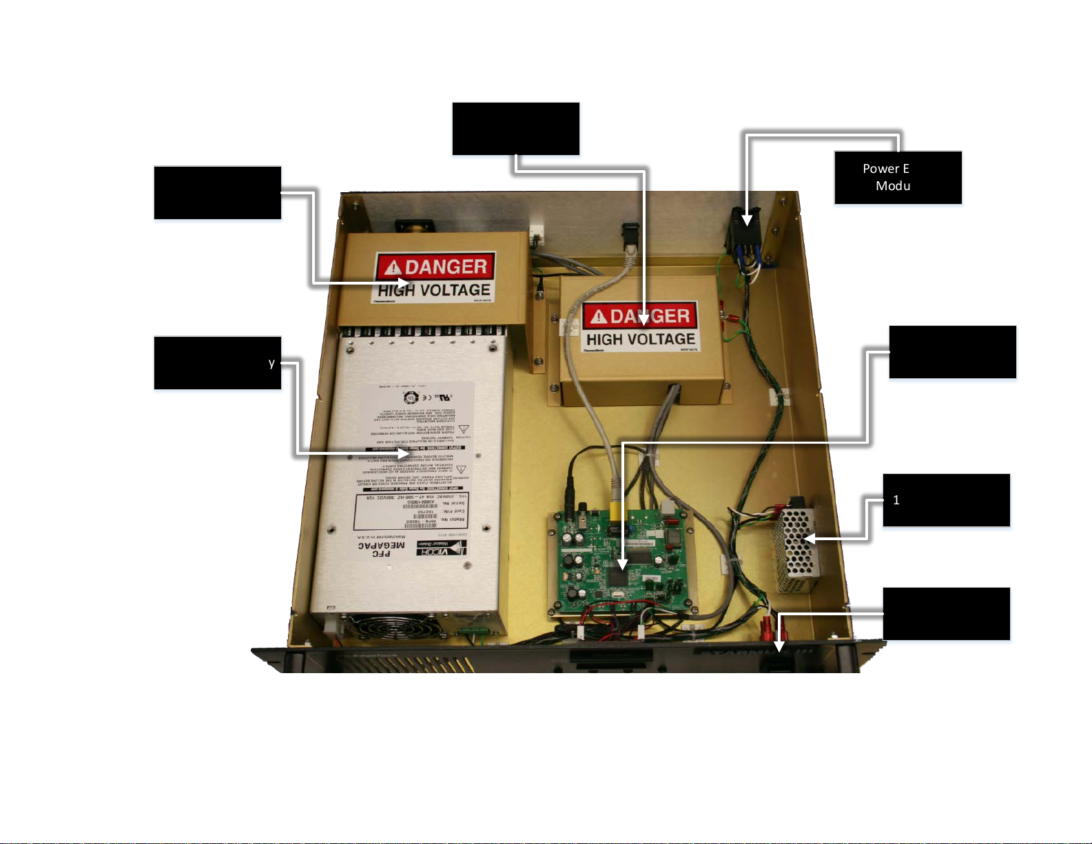
375 V Power Supply
12 V Power Supply
Modem Board
FSIU Boar d
Sea Cable Interface
Power Entry
Module
Power Switch
Figure 4-3: STARMUX III—Internal Components
Page 58

NE T W O R K L AN
192.9.0.99
SONAR
PROCESSOR
192.9.0.101
ADSL MODEM
192.9.0.23
ADSL MODEM
192.9.0.22
SEA CABLE
INTERFACE
(FSIC)
TOPSIDE INTERFACE
TOPSIDE
TOW VE H ICL E
COMPUTER
ETHERNET
ADSL
ADSL
ETHERNET
SEA CABLE
(ADSL)
LAN
FSIU PCB
ADSL
Figure 4-4: STARMUX III—Block Diagram
Page 59

Figure 4-5: STARMUX III—Wiring Diagram
Page 60

4-8 4.0: TECHNICAL DESCRIPTION
4.2 Towfish
A wiring diagram of the 2000-CSS towfish electronics is shown in FIGURE 4-7, and the electronics chassis is
shown in F
optional pressure sensor. The circuit boards are the following:
IGURE 4-6. The electronics chassis contains all of the towfish circuit boards along with the
Power Distribution The Power Distribution board includes DC to DC converter
module which converts the 400 VDC to +48, +12, -12, and -5 VDC.
The +48 VDC is output on J4 to the Amplifier boards. The other
voltages are output on J6 to the ADSL Modem board, J5 to the
CPU board, J7 to the Sonar Interface board, J8 to the Option
connector, and J9 and J11 to the fans.
ADSL Modem The ADSL Modem board converts the downlink command ADSL
signals received from the 2000 Topside computer and input on J2
from the Power Distribution board into Ethernet
10/100/1000BaseT signals which are output on J1 to the CPU
board. Similarly, the ADSL Modem board converts the uplink
Ethernet 10/100/1000BaseT based data signals from the CPU
board into the ADSL uplink data signals which are output on J2 to
the Power Distribution board for transmission to the 2000
Topside computer. The ADSL Modem board also outputs the FSK
responder trigger signals on J5 to the Sonar Interface board and
to the optional Responder board. +12 and -12 VDC power is input
on J8 from the Power Distribution board.
Wet-End STARMUX III The STARMUX III Wet-End electronics inputs the towfish 400 VDC
power on J1 from the 2000 Topside computer over the coaxial
tow cable and filters it from the frequency shift keyed (FSK)
responder trigger signals and the ADSL downlink command and
uplink data signals. The command signals are input and the data
signals are output on J9.
2000-CSS COMBINED SONAR 0017423_REV_C
Page 61

4-9
T/R Switch The T/R Switch board provides the transmit/receive function for
the side scan transducer arrays, allowing them to be used both
as acoustic transmitters and as acoustic receivers
simultaneously. Transmit signals are input from the Power
Amplifier board as follows:
J1: Port low frequency transmit
J2: Port high frequency transmit
J3: Starboard high frequency transmit
J4: Starboard low frequency transmit
Amplified transmit signals are output to the transducer arrays or
received signals are input from the transducer arrays as follows:
J8: Port transducer array receive
J14: Starboard transducer array receive
The T/R Switch board also includes four noise reducing receiver
preamplifiers, one each for the high and low frequency port
transducer arrays and one each for the high and low frequency
starboard transducer arrays.
Power Amplifier There are four identical Power Amplifier boards, one each for the
port high (SSH) and low (SSL) frequency transmit signals and one
each for the starboard high and low frequency transmit signals.
+48 VDC is input on J2 from the Power Distribution board, and
the amplified outputs are output on J3 to the T/R Switch board
to drive the transducer arrays. On/off control signals, along with
the low level transmit signals, are input on J1 from the Sonar
Interface board.
CPU The CPU board runs an embedded version of the Microsoft
Windows 7 operating system and includes an 8 GB SATADOM
flash memory with C and D partitions. The C partition contains
the operating system, and the D partition contains the sonar
application software. The CPU board inputs downlink commands
from the 2000 Topside Computer over the Ethernet connection
on J1 with the ADSL Modem board while it outputs the uplink
sonar data to the 2000 Topside Computer over the same
connection. In addition, the CPU provides the chirp matched
filter processing, power up diagnostic self-tests, and pointing
device and keyboard inputs for factory test. The COM1 serial port
of the CPU board interfaces with an optional magnetometer, and
the USB port interfaces with the Compass board. +12 VDC power
is input from the Power Distribution board.
Page 62

4-10 4.0: TECHNICAL DESCRIPTION
Sonar Interface The Sonar Interface board converts the digital chirp high and low
frequency transmit signals for the 100/400-Khz frequency
systems into corresponding low level analog signals which are
output on J9 to the Power Amplifier boards. In addition, signals
from an optional pressure sensor and an internal temperature
sensor are input on J10, the FSK responder trigger signals are
input on J4, and the digitized received sonar signals from the Side
Scan board are input on J7. Test points and indicators for the
transmit signals and IDE interface logic for the Side Scan board
are also included. +5, +12 and -12 VDC power is input on J5 from
the Power Distribution board.
Side Scan The Side Scan board is a four channel receiver that provides
(Legacy Systems) analog to digital conversion of the received sonar signals which
are input on J1 from the T/R Switch board. The digitized signals
are output on J2 to the Sonar Interface board. Indicators on the
Side Scan board illuminate when signals are being received.
Sub-Bottom The Sub-bottom board is a single channel receiver that provides
analog to digital conversion of the received sonar signals which
are input from the hydrophones on J4 on the electronics bottle
connector end cap. The digitized signals are output on J2 to the
Sonar Interface board. Indicators on the Sub-Bottom board
illuminate when signals are being received.
Compass The Compass board provides heading, pitch and roll outputs to
the USB port of the CPU board.
4-Port USB to Serial Used to convert USB port signals to serial port signals used to
Adapter connect optional serial port peripheral components to the J4
bulkhead connector. Port 0 and Port 1 from the USB to serial
adaptor are connected to the J4 bulkhead connector.
2000-CSS COMBINED SONAR 0017423_REV_C
Page 63

Sub-Bottom Power Amp T/R Switch PCB
Powe r Amps
(SSH/SSL Starboard)
4-Por t Serial-to-USB
Adaptor
Powe r Amps
(SSH/SSL Port)
Power Dist ribution PCB
ADSL
Modem
SIB U
DDC Board
(SS in Legacy Systems)
Sub-Bottom Board Compass
Wet -End STARM UX II I
CPU
Figure 4-6: Towfish—Electronics Chassis
Page 64

Figure 4-7: Towfish—Block Diagram
Page 65

4-13
4.3 Cables
Outline drawings of the optionally available tow cable and test cable are listed below along with their
corresponding figure numbers.
IGURE 4-8: ARMORED CABLE, PMI GRIP, UNTERMINATED TOPSIDE
F
F
IGURE 4-9: TEST CABLE
Page 66

Figure 4-8: Armored Cable, PMI Grip, Unterminated Topside
Page 67

Figure 4-9: Test Cable
Page 68

Page 69

5-1
5.0: MAINTENANCE
The 2000 Series Combined Side Scan Sonar and Sub-Bottom Profiling System is ruggedly designed and
built and therefore requires little maintenance. However, to ensure long lasting and reliable service, some
periodic maintenance is recommended.
This section provides some maintenance recommendations and includes instructions on how to
disassemble and reassemble the 2000-CSS towfish should it be required to access and remove the
electronics chassis in the electronics bottle. In addition, instructions on how to calibrate the compass are
included, along with troubleshooting guides and lists of major components for the 2000 topside computer
and the 2000-CSS towfish.
5.1 Periodic Maintenance
Maintenance on the 2000-CSS should be performed on a regular basis or as often as necessary, depending
on use. However, most of the maintenance is performed after each deployment and recovery cycle of the
towfish. No periodic maintenance is required for the Rack Mount topside.
5.1.1 Inspecting and Cleaning the Towfish and Tow Cable after Use
After retrieving the towfish from the water, use a hose to wash it down, along with the tow cable, with
clean, fresh water. Thoroughly spray the transducer arrays and remove any buildup of debris. Inspect the
cables and connectors for any damage and check for loose connections. Also inspect the tow cable and
the connectors on each end.
After washing down the towfish, clean the transducer arrays using a mild, non-abrasive detergent and
water. Do not use any abrasive detergents or ammonia based cleaners. After cleaning, thoroughly spray
the transducer arrays again with fresh water.
5.1.2 Inspecting and Cleaning the Underwater Connectors
Regularly inspect the contacts on the male pins of each underwater connector in the towfish and on the
tow cable for corrosion or oxidation. To remove any oxidation, rub the contacts lightly with 800 grit emery
cloth cut into strips equal to or less than the width of a contact. A pencil eraser can also be used for this
purpose. The female sockets can be cleaned using a cotton swab and rubbing alcohol. A .22 caliber bore
brush with only nylon bristles can be used to remove light oxidation.
To extend the life and increase the reliability of the connectors, apply a thin film of silicone dielectric
grease, such as Novagard® G624 ® general purpose silicone grease or an equivalent, to the entire surface
of each male pin. A small amount of grease should also be applied to the opening of each female socket.
Page 70

5-2 5.0: MAINTENANCE
NOTE: Remember to always install dummy connectors on the connectors
of the tow cable and the towfish tow cable connector.
5.1.3 Storage
When not in use, all the components of the 2000 Series Combined Side Scan Sonar and Sub-Bottom
Profiling System should be packed in their original shipping containers in the same manner in which they
were originally shipped and stored in a dry area.
5.1.4 Recommended Spares
Spares, such as circuit boards, power supplies, cables, and other critical items should be purchased at the
same time as the system is purchased, as some original equipment manufactured (OEM) components may
change. All spares are optional. For a list of recommended spares at the time of the system purchase,
contact EdgeTech sales.
5.2 Restoring the Operating System to the Hard Drive
The Topside Computer contains a 160-GB hard drive for both the operating system and the application
software. A separate 1-TB hard drive is also included for data recording. An image file of the 160-GB hard
drive is provided on a CD. This CD can be used to completely restore the 160-GB hard drive to its original
shipped factory configuration in the unlikely event of its failure (see A.0:
SYSTEM RESTORE).
5.3 Disassembling and Reassembling the Towfish
The procedures below describe how to disassemble and reassemble the towfish to access and remove
the electronics chassis. The tools required are a 9/16-inch wrench, a 7/16-inch wrench and a ½-inch
Allen key.
WARNING! High voltages that can cause injury or death are present in
the towfish. Turn off both the Topside Computer and the STARMUX III
and disconnect the tow cable before disassembling the towfish.
2000-CSS COMBINED SONAR 0017423_REV_C
Page 71

5.3.1 Disassembling the Towfish
Bottle clamp
Transducer
Electronics
bottle
Socket head cap screw (3)
End cap
To disassemble the towfish:
1. Place the towfish on a clean, dry, flat surface.
2. For the 2000-CSS Towfish, use the 7/16-
inch wrench and remove the four bolts
securing the teardrop cover to the towfish
and remove the cover.
3. Using the 9/16-inch wrench, remove the
four sets of nuts, flat washers and lock
washers securing the two bottle clamps
and remove the clamps. These items are
shown in F
4. Disconnect all the cables from the
connector end cap of the electronics
bottle and remove the bottle from the
towfish. The connector end cap is shown in
F
IGURE 5-2.
IGURE 5-1.
5-3
Figure 5-1: 2000-CSS Towfish with
Teardrop Cover Removed
5. Using the ¼-inch allen key, remove the
three socket head cap screws from the
connector end cap.
6. Insert the socket head cap screws into the
three end cap removal holes on the
connector end cap.
7. Using the ¼-inch allen key, evenly screw
each of the socket head cap screws into the
end cap to extract it.
8. When the end cap is free of the housing,
carefully slide the electronics chassis
completely out of the housing and lay it on
a clean flat surface.
removal
hole (3)
Figure 5-2: Electronics Bottle Connector End Cap
Page 72

5-4 5.0: MAINTENANCE
WARNING! With the towfish powered, high voltages that can cause injury
or death are present on the electronics chassis. Use caution when
working on the electronics chassis with the towfish powered.
5.3.2 Reassembling the Towfish
Before reassembling the towfish, clean the two O-rings on the end cap with a lint free paper towel and
inspect them for any scratches, nicks or dirt. If any of these conditions exist for an O-ring, discard the Oring and install a new one. When installing a new O-ring, first clean the O-ring surfaces on both the housing
and the end cap with the paper towel, and then apply a light coating of silicone lubricant to the new Oring around its entire surface and install it. If no scratches, nicks or dirt are found when cleaning the Orings, leave them installed and apply a light coat of silicone grease only.
To reassemble the towfish, reverse the disassembly procedure. However, when reassembling the end cap
to the housing, line it up as shown in F
IGURE 5-2 with the arrow pointing up.
5.4 Calibrating the Compass
The compass is calibrated at the EdgeTech manufacturing facility. Should the compass in the towfish lose
its calibration for any reason in the field, it may be necessary to recalibrate it. This is accomplished by
accessing the embedded Windows installation in the towfish itself via a remote desktop application on
the Rack Mount Topside.
Furthermore, it is necessary to physically move the towfish around in different positions for the compass
within it to establish the necessary reference points. The support of at least two survey technicians, and
a rotating table (as shown in the procedure to follow) or winch for hoisting and rotating the towfish are
essential:
1. Power up the Rack Mount Topside with towfish connected.
2. Click on the Remote Desktop icon (F
Figure 5-3: Remote Desktop Icon
IGURE 5-3) and click Connect on the splash screen (FIGURE 5-4).
2000-CSS COMBINED SONAR 0017423_REV_C
Page 73

Figure 5-4: Remote Desktop Splash Screen
5-5
3. If a warning pops up as shown in F
IGURE 5-5, click Yes before proceeding.
Figure 5-5: Remote Desktop Warning Screen
Page 74

5-6 5.0: MAINTENANCE
4. In the remote desktop program, the embedded Windows installation in the towfish will become
accessible. Shut down the Sonar.exe application running (see F
Figure 5-6: Closing Sonar.exe
IGURE 5-6 below):
5. On this desktop, click on the Tera Term command console icon (F
(F
IGURE 5-8), click OK.
Figure 5-7: Tera Term Icon
IGURE 5-7). At the splash screen
2000-CSS COMBINED SONAR 0017423_REV_C
Page 75

5-7
Figure 5-8: Tera Term Splash Screen
6. Establish communications with the SSAHRS and verify via a serial console.
.
Page 76

5-8 5.0: MAINTENANCE
Figure 5-9. Terra Term Port Set-up
Figure 5-10. Motion Sensor Serial Output
7. Stop the device and retrieve the current level 2 (factory) calibration using the following two
commands.
stop <CR>
getLevel2CompassCalibration <CR>
8. Ensure that the points are 0, the error percentage is 100.0%, the hard iron values are all 0.0, and
that the soft iron values are an identity matrix (see F
IGURE 5-11).
2000-CSS COMBINED SONAR 0017423_REV_C
Page 77

Figure 5-11. Motion Sensor Calibration Result
5-9
If for some reason they are not; reset SSAHRS with the following command and then cycle power.
setLevel2CompassCalibration,factory2015,0,100.0,50.0,0,0,0,
1,0,0,0,1,0,0,0,1 <CR>
9. Restart the SSAHRS by issuing the following command, to start compass data:
start <cr>
Heading, Pitch, Roll, and Temperature should begin to scroll.
Page 78

5-10 5.0: MAINTENANCE
Figure 5-12. Motion Sensor Serial Output
10. Slowly move the vehicle around in such a fashion as to position the compass in as many possible
orientations as possible for pitch, roll and heading directions.
a. UUT in neutral position : Pitch/Roll ~0 degrees, rotate device thru 360 degrees of heading
(10 times)
Figure 5-13: Tilt 0 degrees
b. UUT in Pitch/Roll ~-90 degrees, rotate device thru 360 degrees of heading (10 times)
Figure 5-14: Tilt -90 degrees
2000-CSS COMBINED SONAR 0017423_REV_C
Page 79

c. UUT in Pitch/Roll ~+90 degrees, rotate device thru 360 degrees of heading (10 times)
Figure 5-15: Tilt +90 degrees
11. At the serial console, execute the following commands.
5-11
stop <CR>
getCurrentCompassCalibration <CR>
12. The compass solution will be displayed to the user as well as the number of points, magnitude of
the magnetic field at this location, and the fit error. If the solution is not viable the device should
be returned to streaming with the start <CR> command and steps 8 through 10 should be
repeated until the fit error is ≤ 1.0% and Points is > 100.
a. Valid solution:
Figure 5-16: Compass Calibration Table
b. If the solution was acceptable, Fit Error ≤ 1.0 % record and provided product engineer
along with the vehicle type. Finally, save the data into the factory calibration (level2)
portion of the device with the following command then cycle power:
setLevel2CompassCalibrationFromCurrent, factory2015 <CR>
c. Verify Factory Compass Calibration has been set by issuing the following commands:
Page 80

5-12 5.0: MAINTENANCE
Stop <CR>
getLevel2CompassCalibration
13. At this point, the SSAHRS calibration is complete. Close out of remote desktop.
5.4.1 Changing the Angle of Declination
The compass' angle of declination is set to true north at the EdgeTech facility. However, to provide a more
accurate target location, it is necessary to enter the known magnetic declination for the survey location
into the compass as follows:
1. Repeat steps 1 through 6 in Calibration procedure in section 5.4.
Figure 5-17
2. Verify current Declination Angle of Deviation using the following command:
getDeclination <CR>
2000-CSS COMBINED SONAR 0017423_REV_C
Page 81

Figure 5-18
5-13
3. Enter the set declination command to get help for command:
setDeclination <CR>
Help for command:
setDeclination, [D]
[D]: Declination angle (degrees), which is the correction between magnetic north and true
north. This value depends on geographic location.
Declination for your location can be found by going to the following website:
http://www.ngdc.noaa.gov/geomag-web/#declination
Here is an example of how using this website can help you to determine your angle of
deviation:
Page 82

5-14 5.0: MAINTENANCE
• Zipcode 02360 was inserted, then "Get & Add Lat/Lon" was selected:
Figure 5-19: Magnetic Declination Estimated Value Screen
2000-CSS COMBINED SONAR 0017423_REV_C
Page 83

• "Calculate" is then selected:
5-15
Figure 5-20: Angle of Declination Calculated
• The Declination Angle received was 14.47 degrees. This is the angle that will be entered
into the TeraTerm command screen.
4. Enter the Declination Angle using the command:
setDeclination, 14.47 <CR>
Page 84

5-16 5.0: MAINTENANCE
5. Verify entry of declination Angle using the command:
getDeclination <CR>
Figure 5-21
2000-CSS COMBINED SONAR 0017423_REV_C
Page 85

6-1
6.0: TROUBLESHOOTING
Should some operational or performance problems occur with the 2000 Series Combined Side Scan Sonar
and Sub-Bottom Profiling System, it may be possible to correct them using the troubleshooting guides in
the following pages. For the Topside Computer and the STARMUX III Digital Telemetry Link, tabular
troubleshooting guides are provided in T
identify some symptoms that could occur and presents one or more possible causes and the
recommended corrective action for each. Perform the corrective action for any given symptom in the
order of possible causes, which generally corresponds to the degree of troubleshooting difficulty, from
the simple to the more complex.
ABLE 6-1 and TABLE 6-2, respectively. These troubleshooting guides
For the towfish, detailed information is provided in the T
Before proceeding with any corrective action, verify that the 2000 Topside computer is plugged into an
appropriate AC or DC power source and that it is switched on.
NOTE: Be sure to also verify that all the cables on the 2000 Topside
computer and the towfish are mated and are not loose or damaged. Most
causes of operational or performance problems are a result of poor
connections.
OWFISH TROUBLESHOOTING GUIDE.
6.1 2000 Topside computer Troubleshooting Guide
SYMPTOM PROBABLE CAUSE CORRECTIVE ACTION
The green SYSTEM POWER
indicator on the 2000 Topside
computer does not illuminate
when the processor is turned on.
The POWER switch is not turned
on.
No AC power.
Verify that the POWER switch
on the back panel is on.
Verify that the 2000 Topside
computer is connected to AC
power. Check the AC power
source.
The indicator is not operating.
Open the 2000 Topside
computer and check the
indicator and wiring.
Page 86

6-2 6.0: TROUBLESHOOTING
Check all connections to
SYMPTOM PROBABLE CAUSE CORRECTIVE ACTION
Open the 2000 Topside
computer and verify that the
160-GB hard drive is connected
to power and that the ribbon
cable is properly plugged in.
Also verify that the ribbon cable
in properly plugged into to the
CPU board.
The yellow HDD indicator on the
2000 Topside computer does
not flash when the processor is
turned on.
The operating system is not
booting.
The DISCOVER reports “Cannot
ping towfish.”
The DISCOVER reports “Cannot
ping towfish.”
The indicator is not operating.
Open the 2000 Topside
computer and check the
indicator and wiring.
Tow cable disconnected. Check tow cable connections.
LAN settings are not properly
setup.
Modem settings incorrect.
Modem disconnected internally
on topside.
Refer to TCP/IP ADDRESS SETTINGS
Contact EDGETECH CUSTOMER
SERVICE
modem are correct per
Document No. 990-0000046-
1000.
In DISCOVER 2000-C Dual
Frequency Side Scan, choose
Improper settings in DISCOVER.
Network from the Configuration
menu and verify that the Sonar
IP Address is 127.0.0.1 and the
Sonar Port Number is 1602.
2000-CSS COMBINED SONAR 0017423_REV_C
Page 87

SYMPTOM PROBABLE CAUSE CORRECTIVE ACTION
In DISCOVER Sub-Bottom,
choose Control Panel from the
Sonar menu and select the
Network tab from the Options
dialog box. Verify that the
TCP/IP Address is 127.0.0.1 and
the TCP/IP Socket is 1600.
Verify towfish on a different
The towfish is faulty.
Table 6-1: 2000 Topside computer—Troubleshooting Guide
2000 Topside computer. Verify
2000 Topside computer with a
different towfish.
6-3
6.2 STARMUX III Digital Telemetry Link Troubleshooting
Guide
SYMPTOM PROBABLE CAUSE CORRECTIVE ACTION
The green POWER indicator
does not illuminate when the
unit is turned on.
The green LAN indicator does
not illuminate when the unit is
turned on.
The POWER switch in the front
or rear of the unit is not turned
on.
No AC power. When using AC
power connector.
5 amp fuses on rear panel VAC
connection are bad.
The indicator is not operating.
There is no connection between
the digital link and the external
topside computer.
The indicator is not operating.
Verify that both POWER
switches are on.
Verify that the digital link is
connected to AC power. Check
the AC power source. Verify
that the fuse is good.
Check fuses for continuity.
Replace if necessary.
Open the unit and check the
indicator LED and wiring.
Check the LAN connections
between the STARMUX III unit
and the topside computer.
Open the unit and check the
indicator LED and wiring.
Page 88

6-4 6.0: TROUBLESHOOTING
Tow cable between the digital
SYMPTOM PROBABLE CAUSE CORRECTIVE ACTION
The green LINK indicator flashes
when the STARMUX III is turned
on. After 1 minute, flashing
should stop and indicator should
remain lit.
The red FISH POWER indicator
on the digital link illuminates
after 10 seconds, then turns off
after 20 seconds.
link and the towfish is
disconnected or faulty.
Modem settings on the digital
link are incorrect.
Tow fish is faulty.
The tow cable is not connected
between the digital link and the
tow fish.
Tow cable is faulty.
Power board is faulty.
Towfish is faulty.
Check connections and tow
cable.
Contact EDGETECH CUSTOMER
SERVICE.
Check the unit using a different
tow fish.
Check the tow cable
connections to the rear panel of
the digital link and connection
to the towfish.
Check continuity between
connectors and proper wiring.
Verify that RED LED D2 turns on
after 10 seconds.
Verify the towfish on a different
digital link. Verify the digital link
on a different towfish.
The DISCOVER survey software
(if used on external topside)
reports “Cannot ping towfish”
2000-CSS COMBINED SONAR 0017423_REV_C
LAN cable disconnected. Check LAN cable connection.
Tow cable disconnected. Check tow cable connection.
Modem settings are incorrect.
Contact ERROR! REFERENCE SOURCE
NOT FOUND.
Check all connections to the
Modem disconnected internally
on digital link.
modem are correct per the
wiring diagram, EdgeTech PN
0009221
Check that under
Improper settings in DISCOVER
II (if used on external topside).
“Configuration” pull down
“Network” the displayed
address is 192.9.0.101 with
“Port” set to 1700.
Page 89

6-5
SYMPTOM PROBABLE CAUSE CORRECTIVE ACTION
Verify the towfish using a
Towfish is faulty.
Table 6-2: STARMUX III Digital Telemetry Link—Troubleshooting Guide
different digital link. Verify the
digital link with a different
towfish.
6.3 Towfish Troubleshooting Guide
The towfish is a computer controlled device. Therefore, in order to troubleshoot such a complex piece of
equipment to a sub-module level, one must have the proper test equipment and thorough knowledge of
the unit’s electrical operation plus hardware aspects. The purpose of this section is not to develop those
techniques nor provide a step-by-step procedure where one may start and end up at the point of failure.
It is to give an operator some familiarity with the electronic hardware. The following sections provide
some specific areas to check which are easily identifiable and certain clues as to what to look for in making
an educated guess as to the source of the problem. This is only down to the module or PCB level.
The towfish is a software controlled computer system. There are also some analog sections that interface
with the towfish transducers. Being a digital device, many operating portions use the same data and
address lines a failure of one may result in a failure of all. This makes it very hard to isolate some digital
problems without the proper equipment and a thorough knowledge of the data flow. This equipment is
not normally found on a vessel.
The primary objective is to ascertain which system component is at fault. First, ensure that the system is
properly installed with all connections properly mated. Next, check that the line voltages for the topside
components are within specified limits and any fuses have not blown. Fuses may fail if a wrong connection
has been made during setup. They have also been known to fail for no apparent reason. Always replace
fuses with those of the same value. If a fuse fails again within a short time, there are more serious
problems within the corresponding unit.
Open the cover of the topside electronics and check that all the cards are seated, especially if the unit has
been in transit. After checking the cards, ensure that the cable connectors are properly mated. If the
problem still persists, disengage and then reengage all PC boards and do the same for all board cable
connections, before going on to any electrical testing.
All calibration adjustments are preset at the factory and should not require any modifications in the field
unless certain mechanical and/or electrical components are changed or the adjustments are inadvertently
altered.
If the above checks do not identify or remedy the problem, attempt to isolate the failure to one of the
major system components: the sonar processor, the modem/power unit, the towfish, or the tow cable.
The following presents various operational problems and general comments on where to look and what
to look for.
Page 90

6-6 6.0: TROUBLESHOOTING
The main objective is to get the basic system working. It is therefore good practice to disengage any option
circuit cards installed in the unit and optional external system components at this time to reduce the
number of possible trouble sources.
6.3.1 Equipment Required
Except for the topside computer/power unit, only common laboratory test equipment and tools are
required for field troubleshooting. No special equipment is necessary. Typical test equipment includes:
• Digital multi-meter, Fluke, or equivalent
• Oscilloscope
• Hi-pot tester
• Capacitance meter
6.3.2 Transmission Verification
The 2000-CSS Towfish is different conventional side scan sonars used for many years. The early sonars
were driven with a high-powered energy burst similar to hitting a bell with a hammer. The transducers
are driven with a smooth rising lower power signal that matches the transducer response. Because of this,
there is no pronounced clicking noise emanating from the transducers when they are firing. Therefore,
the ‘listen for the clicking noise’ test cannot be used to verify sonar transmission during bench or on-deck
testing.
Sniffing with an oscilloscope can be used as a substitute to check transducer firing. One way is to attach
the scope probe’s ground to the towfish body and hold the open probe next to the transducer under test.
Set to about 20 to 50mV /Div.
A second method is to connect a several-turn wire loop across the scope probe and move it over the
transducer face. Electrical pickup should be noticed on the scope screen at each transmission burst.
Remember that the transducers and elements within the transducer may be firing together or in
sequence. One must make sure that the electrical pickup is not from an adjacent string.
6.3.3 Sonar Processor and Data Link
It is assumed that the sonar processor is up and working in order to complete system test and
troubleshooting. Refer to the sonar processor’s manual for its troubleshooting and diagnostic
information.
The other thing is that the high-speed data must be up and running so that the topside and sub-sea units
are communicating with each other. If the towfish boots up correctly and passes its internal self-test,
2000-CSS COMBINED SONAR 0017423_REV_C
Page 91

6-7
there will be a smooth sequence of rising tones going from 2 to 3.9 kHz. A set of tones jumping from 2 to
3 kHz means that self-test has failed. These tones are generated in software in the towfish and replicated
on the surface when an EdgeTech topside computer is used to access the Towfish computer subsystem
using the Remote Desktop application. The Self-Test PASS tones repeat until data linkup has occurred
between the topside DISCOVER software, and towfish. Self-Test FAIL tones repeat indefinitely.
There will also be a video acknowledgement of successful self-test and linkup in the topside computer's
DISCOVER display window. Self-test status will also be displayed on an external video monitor if attached
directly to the towfish’s CPU board's VGA connector.
If the topside computer is unavailable and the towfish is dismantled, an external keyboard, mouse and
video monitor may be connected to the towfish’s CPU board to provide some diagnostic testing. An
external power unit will still be required.
6.3.4 Topside Power Unit
Towfish power is supplied either from an individual power/modem unit or from an integrated topside
computer. Voltage and current to the towfish are important parameters. They must be within acceptable
limits for the towfish to work properly. Check the tow cable output voltage with the system connected
and, if possible, the current drain with an inline connection. Cable current should be between 120mA
(Idle) and 250mA.
The topside units supply 400VDC to the tow cable. The voltage at the towfish end of the cable must be
not less than 300VDC to start the system and not be less than 200V during operation.
6.3.5 Command and Data Link
To check that the command and data link over the tow cable is operational, start the Remote Desktop
application on the topside control computer. There is normally a shortcut on the EdgeTech Desktop for
this. The towfish's PC screen should appear in a window on the topside computer screen. This will appear
as a yellow desktop with the sonar application dialog box visible. If this is successful, then the command
link is working.
6.3.6 Data link
A good, quick qualitative test of the data link and towfish electronics is to perform a rub test on each
transducer. Set the Range to 200 meters for both frequencies and start the system running in HDM mode
for both. Set screen gain to +30dB for both frequencies and briskly rub each aft transducer face one at a
time. A dark band should appear on the sonar processor screen corresponding to the side rubbed.
Data throughput rates on the uplink (vehicle to topside) can be critical in getting smooth data from the
towfish. The data throughput rate can be checked using EdgeTech supplied utilities at each end of the link
Page 92

6-8 6.0: TROUBLESHOOTING
The SockBlast application is used to test network throughput between the towfish and the topside
computer. This application is normally kept in C:\EdgeTech\Utilities folder on the topside unit, and
D:\EdgeTech\Utilities folder on the towfish.
Figure 6-1: SockBlast Window
Two copies must be run one on each computer. One serves as the client (topside) and the other as the
server (towfish). Since the client connects to the server, the Create Client (topside) address must be the
TCP/IP address of the server (towfish) machine, which is 192.9.0.99. The towfish Create Server address
should be 0.0.0.0.
After pressing the Create buttons to start the server and clients on their respective machines, the two
applications hook up, then the Client count on the towfish should increment from 0 to 1 and the Server
count on the topside should increment to 1 as well. This indicates that there is one connection between
the two applications
Check the Server Send Data box on the towfish. A performance in MB/second will be displayed. This
should be more than 0.35Mbyte/s.
6.3.7 Towfish
First verify that the command and data links between the towfish and topside are working per above.
NOTE: It is recommended that all attempts be made to see if a problem
is external to the towfish before opening it.
WARNING! High voltage (400 VDC) is always present in the electronics
assembly when powered.
2000-CSS COMBINED SONAR 0017423_REV_C
Page 93

6-9
6.3.7.1 Preliminary
When the electronics has been removed:
1. Check that all boards are still secured to their mountings.
2. Check the mating of all connectors
3. Check that the terminal board screw connections are tight
4. Check for obvious hot /burn spots by sight and smell.
6.3.7.2 No Sonar Data
If the sonar display doesn’t scroll, use the ‘scope sniffing’ approach as outlined in TRANSMISSION
VERIFICATION to check transducer firing. If the transducers are firing, and the data link is working, the
problem is most likely related to the topside computer and/or data modem.
If the display scrolls but is blank and the transducers are firing, the problem most likely lies with either or
a combination of the towfish receiver, transducer or its signal processing circuitry. Establish if the problem
is on a single channel or all channels.
If data is absent in all, or individual channels, check the T/R Switch and SSB boards. If the problem is with
a particular channel, also check the respective power amplifier and transducer element.
Connect to towfish using REMOTE DESKTOP 192.9.0.101 login: administrator, password: admin. Sonar
application should be running and there should not be any errors posted to the window. Errors reported
could be: “No Sonar Device Found”, this will indicate that the CPU does not connect to the sonar processor
card. “IF_DIAG” the sonar processor has detected an error and will not run. Cycle power on towfish
recheck error, if the error is still present check the cables running to and from the sonar interface card.
“HM_Sensors” this reports the 48 volts if this error is found check output of power distribution board in
towfish and also the power on the power amps.
6.3.7.3 Power Supplies
Several power supplies and voltage regulators are located throughout the towfish assembly. The main
ones are located on the Power Distribution board. The first supply converts the 400VDC tow cable voltage
to the operating +48VDC supply. Other DC/DC converters running off the 48 volts generate the low level
operating supply voltages. No supplies are adjustable.
Page 94

6-10 6.0: TROUBLESHOOTING
+5 VDC +/-0.2V
TP7
TP12
+12 VDC +/-0.6V
TP8
TP12
-12 VDC +/-0.6V
TP9
TP12
+27 VDC +/-0.6V
TP10
TP12
+48 VDC +/-2.0V
TP4
TP5
The following are the main voltage test points on the Power Distribution board:
SUPPLY TEST POINT RETURN
Table 6-3: Main Voltage Test Points on Tow Fish Power Distribution Board
Other voltages to check on the SSB board and labeled as such are:
SUPPLY
+3.3 VDC +/-0.1
+5 VDC +/-0.2V
6.3.7.4 Test Lights
1. Power Distribution Board.
Monitor the +400 volt D4 and +48 volt D8 LED’s. They should be on steady.
2. SSB Board.
There are two LED’s of interest. ‘LED A’ flashes when 120 kHz is transmitting. ‘LED B’ flashes when
410 kHz is transmitting.
3. SIB Board.
There are four LED’s of interest. They have the following status when the system is operating
properly.
D1 Off D3 (Orange) Flashes at 2 Hz
D2 Off D4 (Green) On
+12 VDC +/-0.6V
-12 VDC +/-0.6V
Table 6-4: Other Voltages on SSB Board
SSB Board Test Points
2000-CSS COMBINED SONAR 0017423_REV_C
Page 95

6-11
4. GAIN A and B test points show the positive-going TVG ramp voltage for the low and high frequency
sonar channels.
5. Four test points monitor the TVG’d analog sonar data. They are:
ADC 0 Port SSL ADC2 Stbd SSL
ADC 1 Port SSH ADC3 Stbd SSL
These test points are useful when doing a rub test.
6.3.7.5 DDC Test points
This board does not have any test points. LEDs monitors display the channels on the card that are running.
Side A and Side B. In a normally operating vehicle with both channels collecting data the lights will
alternate.
6.3.7.6 Modem Board Test Points
FSK. Monitors the 3200 kHz to 2800 kHz frequency-shift-keyed signal from the topside unit. This signal
is used for optional commands. May not be present in all systems.
Trig. A TTL signal that synchronizes the topside and sub-sea units with other topside equipment.
Follows the SYNC signal input on the topside unit. It is not used in all system configurations.
6.3.7.7 Other Checks
Periodically check the integrity of the sea ground capacitor attached to the rear bulkhead.
6.3.8 Tow Cables
Historically, most system problems occur in the tow cable and their connectors. Before proceeding, verify
cable continuity from the shipboard end of the cable to the towfish. The presence of a shorted or open
wire in a tow cable can be determined by using a multi-meter. An open or shorted wire can be located
using the techniques described in the following subsections.
6.3.8.1 Shorted Wire
The following procedure may be used to approximate the distance to a single short or a point of high
leakage between a conductor pair or from a conductor to a shield.
Disconnect both cable ends.
1. Short the two connector pins (or wires if un-terminated) of the shorted pair at both ends and
measure the total resistance between the ends.
Page 96

6-12 6.0: TROUBLESHOOTING
R1+R2 =_______________
2. Remove the shorts.
3. Measure the resistance between a shorted pair on one end with an ohmmeter on the Rx1 scale.
R1+Rs =_______________
4. Measure the resistance from the other end.
R2+Rs =_______________
5. Add the measurements of 4) and 5) above, subtract the measurement of 2), and divide the result
by 2.
Rs =_________________
6. Subtract the value of 6) from the measured values of 4) and 5).
R1 =_________________
R2 =_________________
7. The distance to the short from end #1 is the ratio of (R1/R1+R2) times the total cable length.
Recheck from end #2 which is (R2/R1+R2) times the cable length.
6.3.8.2 Open Wire
An open wire in a cable is much more difficult to locate than a short circuit; therefore, a capacitance bridge
is recommended. Measuring the capacitance from the open wire to the shield on both ends allows two
different capacitance readings to be recorded. This represents a direct ratio related to cable length and
distance of break from each end. Before cutting the cable, double-check the same ratio of capacitance
using an adjacent good wire in a multi-conductor cable. Capacitance may vary from wire to wire,
depending on their separation.
Most breaks occur around the tow cable termination or where a previous repair has been made. A cable
break may be found or confirmed by laying out the cable and attaching an ohmmeter across each end of
the open wire. Then flex the cable first near the termination or repaired section and then along its entire
length until the break is reached. When flexing, the ends of the broken wire may touch, giving a continuity
reading on the meter.
6.3.8.3 Insulation Resistance Breakdown
Insulation breakdown is the most difficult fault to locate. Cable leakage is not necessarily located near
the end terminations. However, the area near each termination receives the most abuse and is, therefore,
2000-CSS COMBINED SONAR 0017423_REV_C
Page 97

6-13
POWER SUPPLY, 300VDC,
0006370
POWER ENTRY MODULE
0009117
subject to suspicion. Successive cutting of the cable end until leakage disappears will prove successful in
many cases.
CAUTION! Prior to cutting the cable for any of the above reasons, a
careful visual examination should be made for any signs of physical
damage.
With both ends disconnected, the tow cables should measure between 100 Mega-ohms and infinity
between conductors with a 500 VDC Meg ohmmeter. When using a Simpson 260 Multi-meter, all cables
wire-to-wire or wire-to-shield should measure infinity. Any leakage on the multi-meter indicates cable
leakage.
6.3.8.4 Damaged Tow Cable Connector
The towfish has a trip line that prevents the vehicle from hanging up on a snag. When the line trips, the
cable connection to the vehicle disconnects exposing the high voltage pins to seawater. Pin corrosion will
start to occur as long as power is still applied. If the power is not immediately removed, and the cable is
not immediately retrieved and the connector flushed out with fresh water, there may be permanent
damage to the connector. This will require cable re-termination.
6.4 Part Numbers for Major Topside Components
The major 2000 Topside computer components and their part numbers are listed in TABLE 6-5:
DESCRIPTION, PART NUMBER TOPSIDE COMPUTER STARMUX III DIGITAL LINK
CPU, 0004289 X
160GB HDD, 0004983 X
1TB HDD, 0007408 X
MODEM 0016802 X
FSIU, 0006068 X
INDUCTOR, 0003081 X
X
X
Table 6-5: Major Topside Components and Part Numbers
Page 98

6-14 6.0: TROUBLESHOOTING
6.5 Part Numbers for Major 2000-CSS Towfish Components
DESCRIPTION EDGETECH PART NUMBER
RUDDER SB 512I AL YELLOW 0006599
BRACKET RUDDER SB 216 / SB 512I 316 SS 0003405
BRIDLE TOW SB 512I 316 SS 0003432
BRACKET TEAR DROP SB 216 / SB 512I 316 SS 0003412
BRACKET EXTENSION SB 512I 316 SS 0003358
BRACKET MOUNTING SB 216 / 512I TRANSDUCER 304 SS 0003423
HARDWARE SHACKLE STD BOW 0.5 INCH 0006638
HANDLE 12 INCH LONG WITH STUD SS 0005215
STRAP EYE VINYL BLACK 0006791
CONN DUMMY PLUG WETMATE 06 POS FEMALE 0003869
ASSY TOP CABLE 2000 KEVLAR 0.375 COAX TEST 15M WET-WET 0011690
HYDROPHONE ASSEMBLY 0011655
SIDE SCAN TRANSDUCER 0003028
ELECTRONICS CHASSIS 0010181
SPIDER ASSEMBLY 0003179
Table 6-6: Major 2000-CSS Towfish Components and Part Numbers
2000-CSS COMBINED SONAR 0017423_REV_C
Page 99

A.0: SYSTEM RESTORE
The following section outlines the procedures for backing up and restoring the system drive.
CAUTION! All data will be lost upon restoring the system to factory
settings. Be sure to backup all data before preforming the procedure
below.
Ensure that topside is off.
1. Insert USB3 flash drive in blue USB3 port.
2. Start topside and be prepared to press F⋆⋆ key when prompted:
a. If the topside is rack mount, press F11.
A-1
b. If the topside is a laptop, press F12.
3. Under Please select boot device: By using up/down arrow keys, select EUFI: Corsair Voyager 3.0
000A, then press Enter.
4. Wait for Paragon Backup & Recovery 14 Home screen to appear, then click Restore icon.
5. On Welcome to the Restore Wizard screen click Next.
6. On Browse for Archive screen, drag down menu and click on ⊞ to the left of (E:). Click on folder
named as a variation of V⋆.⋆.⋆_⋆⋆⋆⋆R for rack mounts, or V⋆.⋆.⋆_⋆⋆⋆⋆P for laptops. When
Archive File Details window appears, click Next.
7. At What to restore window, click Basic MBR Hard Disk 0, click Next.
8. At Where to restore window, ensure that Basic MBR Hard Disk 0 is already selected (brown box
around it). If it is not, use up/down arrow keys to select. Click Next.
9. At Restore results window, make no selection and click Next.
10. At the Ready to restore from the archive window, select ʘ Yes, apply the changes physically. Click
Next. Restoring will begin.
11. At Completing the restore wizard, click Finish. Click Shutdown.
12. Remove USB3 flash drive and restart topside.
Page 100

 Loading...