

Page 1
1
Model 1500
Portable Dew Point Monitor
OPERATORS MANUAL
399 River Road, Hudson, MA 01749 www.edgetechinstruments.com
508-263-5900 fax: 508-486-9348 h2o@edgetechinstruments.com
Page 2

TABLE OF CONTENTS
1.0 GENERAL DESCRIPTION
2.0 SAMPLE CONNECTIONS
2.1 SAMPLE CONNECTIONS
2.2 ALARM RELAY CONNECTIONS
2.3 OUTPUT CONNECTIONS
3.0 FUNCTIONAL DESCRIPTION
3.1 DISPLAY
3.2 MABC BUTTON
3.3 CLEAN MIRRO RELAY
3.4 FLOW CONTROL VALVE
3.5 ALARM RELAY OUTPUT
Model 1500
Dew Point Monitor
3.6 ANALOG OUTPUT
3.7 DISPLAY “SCAN” BUTTON
4.0 SETUP
4.1 ALARM SET POINTS
4.2 ABC INTERVAL
5.0 MAINTENANCE
5.1 ROUTINE MAINTENANCE
5.2 MIRROR CLEANING SCHEDULE
5.3 MIRROR CLEANING PROCEDURE
6.0 SPECIFICATIONS
7.0 APPENDICES
ROTARY VANE VACUUM PUMP (OPTIONAL)
PRESSURE TRANSDUCER (OPTIONAL)
EDGETECH INSTRUMENTS INC. DEW POINT HYGROMETER SAMPLING
BASIC HUMIDITY DEFINITIONS
BATTERY MATERIAL SAFTY DATA SHEET (FOR -C1 ONLY)
2
Page 3

Model 1500
Dew Point Monitor
Edgetech Instruments Inc.'s Commitment to Quality
To Our Customers:
Thank you for purchasing one of our products. At Edgetech Instruments Inc., it is our policy
to provide cost-effective products and support services that meet or exceed your
requirements, to deliver them on time, and to continuously look for ways to improve both.
We all take pride in the products we manufacture.
We want you to be entirely satisfied with your instrument. The information in this manual will
get you started. It tells you what you need to get your equipment up and running, and
introduces its many features.
We always enjoy hearing from the people who use our products. Your experience with our
products is an invaluable source of information that we can use to continuously improve
what we manufacture. We encourage you to contact or visit us to discuss any issues
whatsoever that relate to our products or your application.
The Employees of Edgetech Instruments Inc.
3
Page 4
Model 1500
Dew Point Monitor
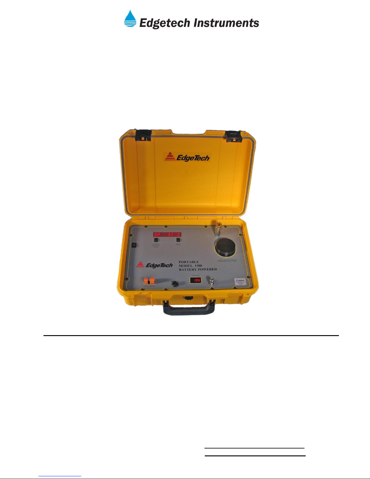
1.0 GENERAL DESCRIPTION
The Edgetech Instruments Inc. Model 1500 Battery Powered DPM is an integrated system
including a microprocessor-based instrument, a chilled mirror dew point sensor, a sample flow
meter and associated tubing and fittings.
The Standard Instrument includes: (Other options available)
An eight-digit, alphanumeric, LED display to report the dew point and system status.
Periodic sensor balance check.
Programmable Alarm Set Point with visual and contact closure alarm indications.
Two SPDT (Form C) Alarm Relay.
4 - 20mA analog output.
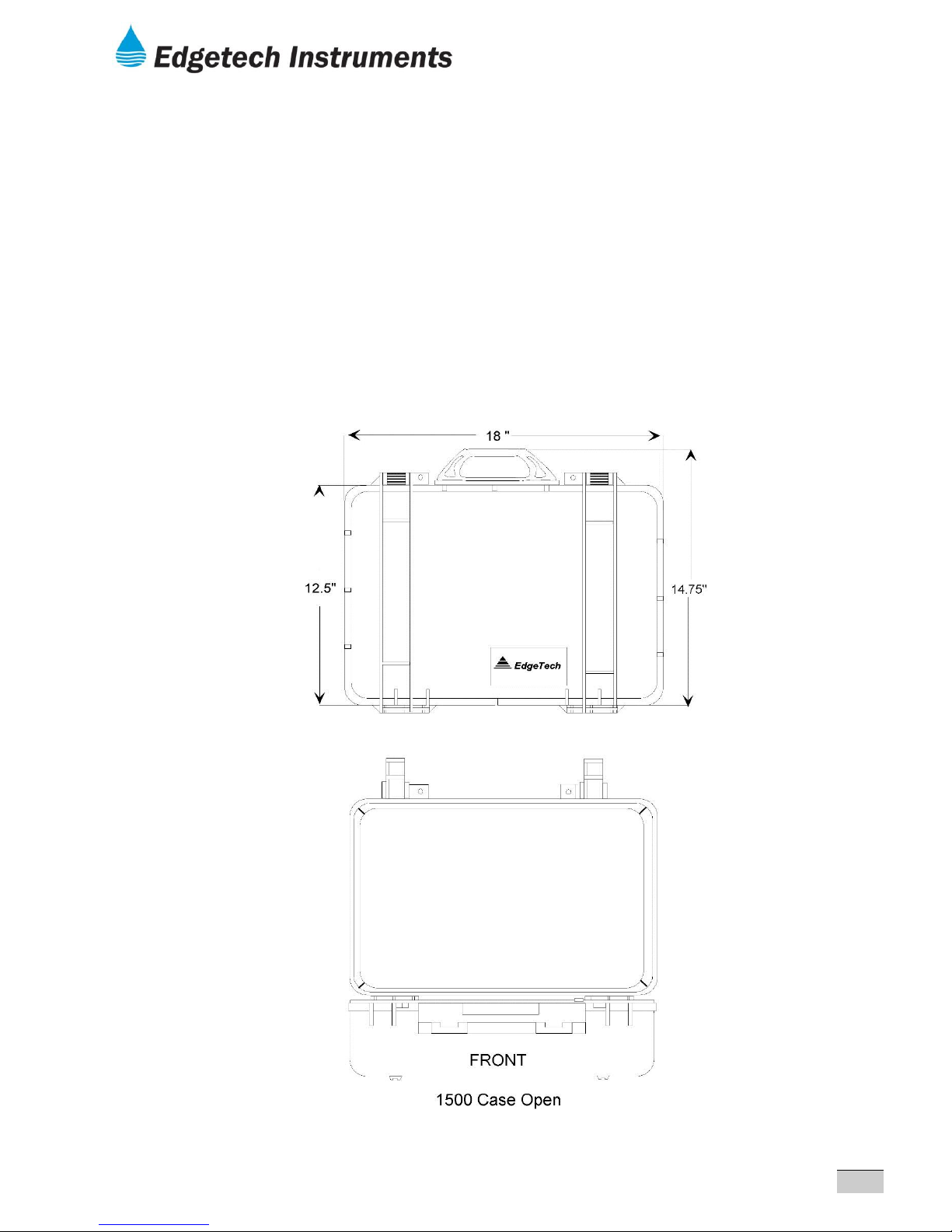
FIGURE 1.1 CASE DIMENTIONS
4
Page 5

Model 1500
Dew Point Monitor
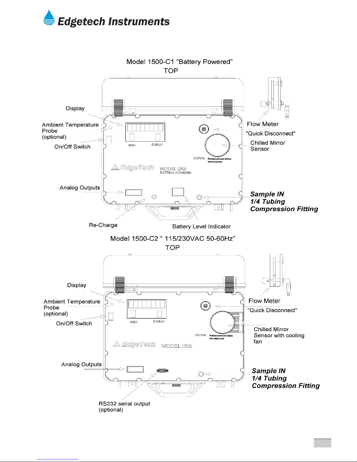
2.0 SAMPLE CONNECTIONS
2.1 SAMPLE CONNECTIONS
The sample may be brought to the instrument with ¼" copper, stainless steel, or plastic tubing
and terminated in a ¼" female fitting.
Connect the sample supply line to the ¼" tubing fitting located on the panel (Figure 2.2).
NOTE: The maximum inlet pressure is 150 PSIG.
Figure 2-2.0 Drawing Model 1500-C1 & Model 1500-C2
Figure 2-2.1 Drawing Model 1500-C1-Sx “underneath”
Figure 2-2.2 Drawing Model 1500-C1-DsX “Insertion Probe”
2.4 ALARM RELAY CONNECTIONS
When the programmed Alarm Set Point conditions are meet, the alarm relay will be energized.
Before connecting any device to the Alarm Relay contacts, check the contact ratings in the
Specifications section.
1. Connect one of the signal wires to the CA (Center Arm) and the other wire to either the NO
(Normally Open) or NC (Normally Closed) terminal. Which ever is preferred by the installer.
(See figure 2.3)
2.5 ANALOG OUTPUT CONNECTIONS
“4-20mA out”. All connection can be made at terminal strip. (See figure 2.3)
1. Connect the high signal wire to the “+” terminal and the low side to the “-“ terminal.
2.6 SERIAL PORT OUTPUT CONNECTIONS (Optional)
1. “RS232 out”. (See figure 2.3)
5
Page 6
Model 1500
Dew Point Monitor
FIGURE 2-2.0 TOP & BELOW PANEL LAYOUT
6
Page 7

Model 1500
Dew Point Monitor
FIGURE 2-2.1
7
Page 8

FIGURE 2-2.2 Model 1500-C1-DSx
Model 1500
Dew Point Monitor
8
Page 9

Model 1500
Dew Point Monitor
FIGURE 2-3 WIRING CONNECTORS
9
Page 10

Model 1500
Dew Point Monitor
3.0 FUNCTIONAL DESCRIPTION
The front panel of the Model 1500 Battery Powered DPM consists of an LED Display and two
push-buttons.
1.) MABC- Manual Automatic Balance Cycle
2.) DISPLAY “SCAN”- Allows viewing of all Parameters or selection of desired measurement.
3.1 Display
The eight character alphanumeric LED display is used to display dew point data
and status messages.
Dew point data is displayed as “DP 34.8 F”, with the units in degrees C or F. (See Set-Up
section)
When a status message is necessary, the display will alternate between the data and the
message at about 2 second intervals.
The possible status messages and their meanings are:
“ABC CYCL” : Indicates that an Automatic Balance Cycle is in progress.
During an ABC Cycle;
The mirror is heated above the ambient temperature for a period of 1 to 3
minutes as determined by the last measured dew point.
After sufficient time has elapsed to ensure that the mirror is dry, the reflected light level of
the mirror is measured and if necessary, adjusted to the reference level.
After the adjustment is made, the instrument will begin cooling and seeking the dew
point. When a stable lock on the dew point is achieved, the “ABC CYCL” message will
disappear, and normal operation will resume.
The analog output is held to the dew point value just before the cycle started until the
completion of the ABC cycle.
If an alarm condition is present when the ABC cycle begins, the audible alarm and the
ALARM display are disabled but the Alarm Relay remains energized.
“ ALARM”: The Alarm Set Point has been exceeded. The Alarm Relay will be energized.
“CLN MIRR”: During an ABC Cycle, the condition of the sensor mirror and optics are
analyzed and a correction is made for changes in the reflectivity since the last cycle. If the
mirror reflectivity has decreased beyond the automatic correction range, this message will
appear at the end of the ABC cycle and indicates that the sensor mirror needs a manual
cleaning. Perform the “Mirror Cleaning Procedure” in the MAINTENANCE and
CALIBRATION Section.
Note: The instrument may appear to operate normally with this message present, but
the data should not be relied upon, until the appropriate maintenance is performed.
10
Page 11

Model 1500
Dew Point Monitor
3.0 FUNCTIONAL DESCRIPTION (CONTINUED)
“CHK SNSR” : If during the ABC Cycle, the reflectivity has increased significantly due to
excessive drift of the optics, or abnormal circuit performance, this message will appear. To
determine the cause, take the following steps.
-Clean the mirror.
-Initiate an MABC Cycle.
-Check the sample system for proper flow.
-Check for loose connections or components on the printed circuit board and sensor.
If the condition cannot be resolved with these checks, contact Edgetech Instruments Inc. for
service.
3.2 MABC Button
Pressing the MABC Button (Manual Automatic Balance Cycle) at any time will initiate an ABC
Cycle.
3.3 Clean Mirror Relay Output
The Clean Mirror Relay is a SPDT relay that is energized whenever maintenance to the mirror is
required.
During an ABC cycle, all alarm functions, including the relay, are disabled.
However, if an ABC Cycle is initiated when an alarm condition is present, the relay will remain
energized until the cycle is complete.
At the end of the cycle the relay will remain energized if the clean mirror condition is still present
or be de-energized if the alarm condition has passed.
3.4 Flow Control Valve
The sample flow rate is adjusted using this valve. Although the sample flow rate is not critical for
proper operation, the recommended rate is 1 – 2 SCFH (Standard Cubic Feet per Hour).
3.5 Alarm Relay Output
The Alarm Relay is a SPDT relay that is energized whenever the dew point exceeds the Alarm
Set Point.
During an ABC cycle, all alarm functions, including the relay, are disabled.
However, if an ABC Cycle is initiated when an alarm condition is present, the relay will remain
energized until the cycle is complete.
At the end of the cycle the relay will remain energized if the alarm condition is still present or be
de-energized if the alarm condition has passed.
3.6 Analog Output
The analog output is a 4 to 20 ma output, proportional to the dew point, and scaled at the
factory for –58 to 122 °F (-50 to 50 °C).
During an ABC Cycle, the output is “held” at the dew point until the cycle is completed.
3.7 Display “SCAN” Button
Display feature allows the viewing of select parameter or scanning of all three
parameters at 3-second intervals.
11
Page 12

Model 1500
Dew Point Monitor
4.0 SETUP
4.1 Alarm Set Point (Figure 4.1)
The alarm set point temperature is set by DIP switch S2 as an integer. The switch setting
represents an eight bit binary number in degrees C with position 8 as the least significant bit
(LSB) and position 2 as the most significant bit (MSB). Position 1 is the sign bit.
An ‘open’ switch is a ‘1’ and ‘closed’ is a ‘0’.
If the desired set point is in degrees F, convert it to Celsius before proceeding.
Set the switches as follows:
1. Convert the desired set point temperature from degrees C to its eight bit binary equivalent
code. Table 4.1 is provided to convert F to C and the equivalent eight bit binary code.
2. Set S1-1 ‘closed’ and S1-2 ‘open’. The alarm temperature setting will be displayed in degrees
C.
NOTE: S1-1 determines whether C or F is displayed in both the measurement and alarm set
modes.
S1-2 will switch the display between the dew point and the Alarm Setting.
3. Set S2, positions 1 through 8 according to the eight bit binary number determined in step 1. A
‘1’ is ‘open’, and a ‘0’ is ‘closed’.
4. The display should now read the set point temperature in degrees Celsius.
5. If Fahrenheit units are desired, set S1-1 to ‘open’.
6. Return to dew point display by setting S1-2 ‘closed’.
12
Page 13

FIGURE 4-1 SETUP
Model 1500
Dew Point Monitor
13
Page 14

C F BINARY C F BINARY
-50.0 -58.0 10110010 0.0 32.0 00000000
-49.0 -56.0 10110001 1.0 33.0 00000001
-48.0 -54.0 10110000 2.0 35.0 00000010
-47.0 -52.0 10101111 3.0 37.0 00000011
-46.0 -50.0 10101110 4.0 39.0 00000100
-45.0 -49.0 10101101 5.0 41.0 00000101
-44.0 -47.0 10101100 6.0 42.0 00000110
-43.0 -45.0 10101011 7.0 44.0 00000111
-42.0 -43.0 10101010 8.0 46.0 00001000
-41.0 -41.0 10101001 9.0 48.0 00001001
-40.0 -40.0 10101000 10.0 50.0 00001010
-39.0 -38.0 10100111 11.0 51.0 00001011
-38.0 -36.0 10100110 12.0 53.0 00001100
-37.0 -34.0 10100101 13.0 55.0 00001101
-36.0 -32.0 10100100 14.0 57.0 00001110
-35.0 -31.0 10100011 15.0 59.0 00001111
-34.0 -29.0 10100010 16.0 60.0 00010000
-33.0 -27.0 10100001 17.0 62.0 00010001
-32.0 -25.0 10100000 18.0 64.0 00010010
-31.0 -23.0 10011111 19.0 66.0 00010011
-30.0 -22.0 10011110 20.0 68.0 00010100
-29.0 -20.0 10011101 21.0 69.0 00010101
-28.0 -18.0 10011100 22.0 71.0 00010110
-27.0 -16.0 10011011 23.0 73.0 00010111
-26.0 -14.0 10011010 24.0 75.0 00011000
-25.0 -13.0 10011001 25.0 77.0 00011001
-24.0 -11.0 10011000 26.0 78.0 00011010
-23.0 -9.0 10010111 27.0 80.0 00011011
-22.0 -7.0 10010110 28.0 82.0 00011100
-21.0 -5.0 10010101 29.0 84.0 00011101
-20.0 -4.0 10010100 30.0 86.0 00011110
-19.0 -2.0 10010011 31.0 87.0 00011111
-18.0 0.0 10010010 32.0 89.0 00100000
-17.0 1.0 10010001 33.0 91.0 00100001
-16.0 3.0 10010000 34.0 93.0 00100010
-15.0 5.0 10001111 35.0 95.0 00100011
-14.0 6.0 10001110 36.0 96.0 00100100
-13.0 8.0 10001101 37.0 98.0 00100101
-12.0 10.0 10001100 38.0 100.0 00100110
-11.0 12.0 10001011 39.0 102.0 00100111
-10.0 14.0 10001010 40.0 104.0 00101000
-9.0 15.0 10001001 41.0 105.0 00101001
-8.0 17.0 10001000 42.0 107.0 00101010
-7.0 19.0 10000111 43.0 109.0 00101011
-6.0 21.0 10000110 44.0 111.0 00101100
-5.0 23.0 10000101 45.0 113.0 00101101
-4.0 24.0 10000100 46.0 114.0 00101110
-3.0 26.0 10000011 47.0 116.0 00101111
-2.0 28.0 10000010 48.0 118.0 00110000
-1.0 30.0 10000001 49.0 120.0 00110001
0.0 32.0 00000000 50.0 122.0 00110010
TABLE 4.1 SETUP
Model 1500
Dew Point Monitor
14
Page 15

ABC
INTERVAL
S1- 6
S1- 7
S1- 8
OFF
0 0 0
4 hrs.
0 0 1
8 hrs.
0 1 0
12 hrs.
0 1 1
16 hrs.
1 0 0
20 hrs.
1 0 1
24 hrs.
1 1 0
28 hrs.
1 1 1
Model 1500
Dew Point Monitor
4.2 ABC Interval
The ABC Interval is the time between the automatic initiation of ABC Cycles. In typical
applications, an interval of 24 hours is recommended and set at the factory. However, in cases
where ambient conditions are more variable, or the sample gas is higher in contaminants, a
shorter interval may be required.
The times listed below are approximate.
The interval is adjustable in 4 hour increments from 4 to 28 hours.
Switch positions S1-6, -7, and -8 represent a three bit binary code with a weight of 4 hrs. per
unit.
To set the interval, set S1-6, S1-7, and S1-8 according to the binary number from Table 4.2
below. The factory default is 24 hrs.
NOTE: ‘CLOSED’ is a zero and ‘OPEN’ is a one.
Table 4.2 converts the required interval in hours to a three bit binary number.
15
Page 16

Model 1500
Dew Point Monitor
5.0 MAINTENANCE
5.1 ROUTINE MAINTENANCE
To ensure the maximum in accurate and reliable operation of any optical chilled mirror system,
a periodic maintenance program should be established.
5.2 MIRROR CLEANING SCHEDULE
Over time, particulates and other matter present in the sample gas and not captured by filters,
build up on the mirror. The result of the buildup of contaminants on the mirror surface is reduced
dry mirror reflectivity and a change in the optical reference point. The ABC Cycle will
automatically readjust the optics to the reference point periodically, but eventually the
adjustment range will be exceeded and a manual cleaning of the mirror may be necessary.
When the contamination becomes too much to be adjusted automatically, an error will be
displayed at the end of the ABC Cycle.
Normally, intervals of 90 days between routine mirror cleanings can be easily achieved.
However, if the sample gas contaminants are particularly high, more frequent mirror cleanings
may be required.
5.3 MIRROR CLEANING PROCEDURE (Figure 5.1)
When mirror cleaning is required as a periodic maintenance item or the “CLN MIRR” or “CHK
SNSR” message appears on the display, proceed as follows.
1. Turn power off.
CAUTION!
When operating with a pressurized sampling system, be sure to remove pressure from
the Sensor prior to removing the Sensor cover.
2. Remove the spin-off cover from the Sensor to expose the mirror.
3. Moisten a clean cotton swab with isopropyl alcohol. Cotton swabs and cleaner are provided in
the Cleaning Kit supplied with the system.
4. Wipe the mirror surface and the optics surface in a circular motion.
5. After cleaning the mirror surface, wipe the surfaces dry with a clean Q-tip.
6. Next, moisten a clean Q-tip with clean, preferably distilled water and wipe the
mirror and optics areas.
7. Dry these areas thoroughly with a clean, dry Q-tip.
8. Replace the sensor cover.
9. Re-establish sample pressure and flow.
10. Turn power on.
16
Page 17

Model 1500
Dew Point Monitor
FIGURE 5.1 S1/S2 WITH COVER REMOVED FOR MIRROR CLEANING
17
Page 18

Model 1500
Dew Point Monitor
6.0 SPECIFICATIONS
Measurement Range
-Dew/ Frost Point –20 to 50°C (Standard S1 Sensor)
-50 to 50°C (Optional S2 sensor)**
-75 to 75°C (Optional S3 sensor)**
-Pressure Transducer 0-150 p.s.i.g. (gauge)
-Ambient Temperature Probe -50C to 50C
-58F to 122F
Measurement Accuracy
-Dew/ Frost Point ±0.25°C (0.45F) Entire Range
-Pressure Transducer 0.5% (Full Scale)
-Ambient Temperature Probe 0.2C (0.36F) Entire Range
Functional
Power/ Charger: 115VAC/60Hz, or 230VAC/50Hz; 40 watts(Max)
Operating Temperature:
Control Unit/Sensor
S-Type 32 to 122°F (0 to 50°C)
D-Type 32 to 185°F (0 to 85°C)
Sample Connection: ¼ female compression tubing fitting
Sample Flow: 0.5 to 5scfh, Integral flow meter
Sample Pressure: 0 to 150psig max
Analog Output: 4 to 20mA, Scaled
Range: Selectable(See available sensor ranges)
Compliance: 9.0 VDC, 450 ohms
Display: Eight Digit Alphanumeric LED, 0.5” High.
High dew point Alarm:
- Visual Flashing Message on Display
- Relay Contacts 2 Form C, non-latching,
10A @ 240VAC
8A @ 24 VDC
½ HP @ 240VAC
Physical
Dimensions: 14.75”H x 18”L x 7”W
Weight: C1(24 lbs.) C2 (14 lbs.)
Standard Features Optional Features
- Microprocessor Controlled. - Pressure transducer; required for PPMv
- 8 Digit Alphanumeric LED Display. - Rotary Vane Vacuum Pump
- Automatic Balance Control.(ABC) - Ambient Temperature; required for %RH
- User settable high alarm limit. - RS232 Serial Port
- Alarm Relay, Form C. - Probe Style Sensor
- Analog Output, 4 – 20 ma.
- Integral flow meter.
- Visual alarms
- Battery Level Indicator & Charger
18
Page 19

Model
Number
Voltage
Max. Flow
L/min
Max.
Pressure
mbar
Min.
Current mA
Max. Current
mA
weight-
grams
13300
6
1.5
120
150
230
38
15317
12
1.9
160
140
200
38
13320
6
2.2
120
180
290
41
14715
9
2.5
150
180
280
41
15320
12
2.6
160
180
270
41
16320
24
2.9
180
130
180
41
16315
24
2.2
80
80
100
47
Model 1500
Dew Point Monitor
7.0 APPENDIX
Rotary Vane Vacuum Pump Specifications
Pressure/Vacuum Pump Models
DC Powered Rotary Vane Pumps
DESCRIPTION
These rotary vane pumps are an excellent pressure/vacuum
source for gas analyzers, medical devices, process samplers
and other analytical instrument applications. They are also
useful for material handling and many general automation
applications.
The pumps are quiet, reliable and mount in any position.
The units operate oil free. The pump vanes have a service life of 10,000 hours and are
easily field replaced without special tools
SPECIFICATIONS
Maximum Differential pressure- 180 mbar
Maximum Flow- 2.9 LPM
Vane Material- Carbon
Note:
Operation at a somewhat lower than
pump design voltage will yield a
significantly longer life of the motor and
the pump while also decreasing the
current draw and operating noise of the
unit.
If used for continuous operation, please
note that the electrical current should be
at least 10% below the specified design
current draw. Consequently, we
recommend that you select a pump that
has a slightly higher pumping capacity
than needed during normal operation.
19
Page 20

Model 205-2
Specifications
Full Scale Pressure Output
5 VDC
Zero Pressure Output
0 VDC
Accuracy
(RSS Method)
±0.11% Full Scale (0.073% Full Scale, optional)
Type of Pressure
Gage or Absolute
Pressure Ranges
0 to 25, 50, 100, 250 psig
0 to 25, 50, 100, 250 psia
Thermal Effects
Compensated Range °F (°C): 30 to 160 (-1 to 65)
%FS/100°F(100°C)max.zero: ±2.0 (±3.6)
%FS/100°F(100°C)max.span: ±1.5 (±2.7)
Media
Gases compatible with 17-4PH stainless steel.
(Hydrogen not recommended for use with 17-4PH
stainless steel.)
Model 1500
Dew Point Monitor
20
 Loading...