

Edgetec TF060-AH-50, TF075-AH-50-HF, TF060-XH-50, TF110-AH-50, TF060-ET-50 Owner's Manual
...
Owner's Manual
TriFlo Spa Bath Pump
2
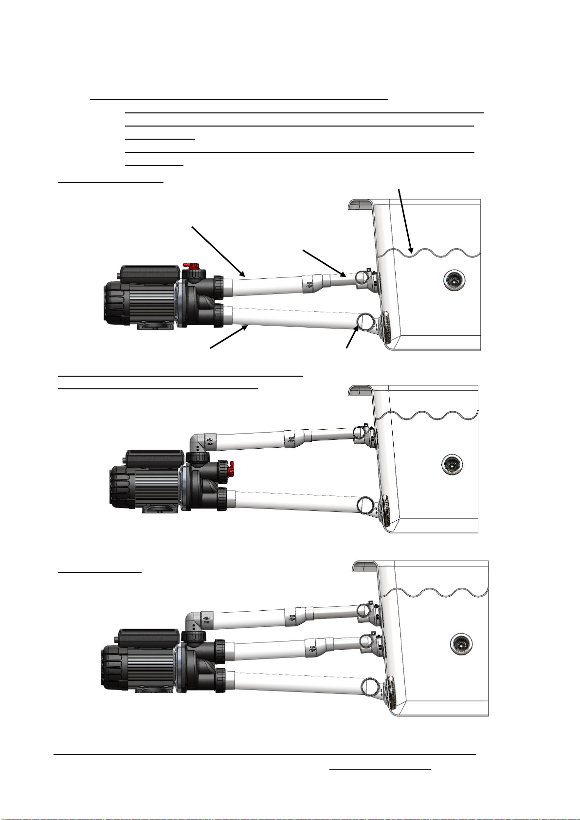
Diagram 1 Correct Spa Bath Pump Installations
Return Line
Return Line
Minimum 1:36 Gradient (1.5°)
Return Line
Minimum 1:36 Gradient (1.5°)
Suction Line
Minimum 1:36 Gradient (1.5°)
Suction Line
Minimum 1:36 Gradient (1.5°)
Suction Line
Minimum 1:36 Gradient (1.5°)
Spa Jets
Water Level Minimum 50 mm Above Spa Jets
Suction
Standard Installation
Top Outlet Installation-Please note the Air Bleed
cannot be activated in this installation.
TriFlo Installation
Use 40mm or 25mm UPVC Pressure Pipe for plumbing installation,
40mm pipe is preferred for both the suction and return lines.
IMPORTANT REQUIREMENT FOR PUMP SERVICE:
Pump installation must provide reasonable access for pump removal.
To allow for pump removal a serviceman must be able to reach the
barrel unions.
Under hob installation- an access panel must be provided on every
installation.
EDGETEC SYSTEMS PTY LTD Part # 9-2100 SEP2015 www.edgetec.net
3
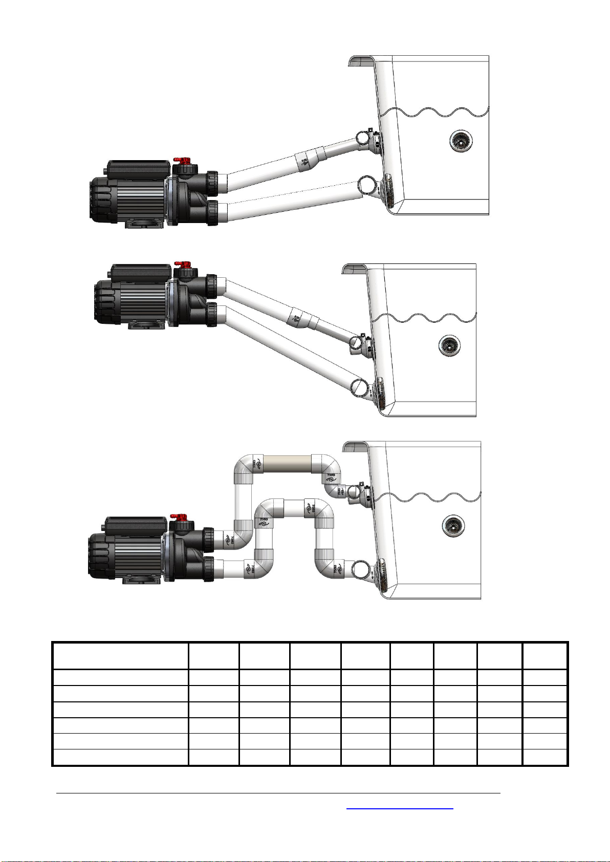
Diagram 2 Incorrect Spa Bath Pump Installations
Pump Model
Supply
Voltage
Power
(watts)
Heater
(watts)
Current
(amps)
Width
(mm)
Height
(mm)
Length
(mm)
dB
Rating
TF060-AH-50
230-240
600 0 3.7
148
198
384
65
TF075-AH-50-HF
230-240
750 0 4.4
148
198
384
65
TF110-AH-50
230-240
1100
0
5.4
148
198
406
65
TF060-XH, ET, ST, SK-50
230-240
600
700
6.8
148
198
384
65
TF075-XH, ET,ST, SK-50-HF
230-240
750
700
7.5
148
198
384
65
TF110-XH, ET,ST, SK-50
230-240
1100
700
8.6
148
198
406
65
X
X
X
INCORRECT PIPEWORK
LOOP-PUMP WILL AIRLOCK
PUMP MOUNTED TO HIGH
PUMP MOUNTED TO LOW
EDGETEC SYSTEMS PTY LTD Part # 9-2100 SEP2015 www.edgetec.net
TriFlo Technical Data
4
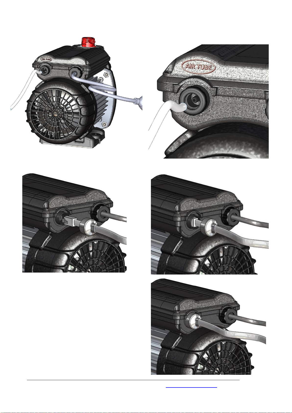
Diagram 3 Air Tube Connections
1. Connect the touch pad cable into
the housing, the alignment is shown
above.
2. Push the connector into the housing
until it “clicks” into the fixed position.
3. Push the protective rubber cap on
the touch pad cable over the
circular housing (failure to do this will
void the warranty).
Attach 3mm flexible air tube
(supplied with the pump)
onto the air switch nipple.
Diagram 4 Touch Pad Connections
EDGETEC SYSTEMS PTY LTD Part # 9-2100 SEP2015 www.edgetec.net
 Loading...