

Page 1

4 Bay SATA II to eSATA RAID5
Storage Appliance
DAS401
User’s Manual
Page 2

Table of Contents
1 WELCOME ........................................................................................................................................................4
1.1 INTRODUCTION ...........................................................................................................................................4
1.2 PRECAUTION ................................................................................................................................................4
1.3 FEATURES .....................................................................................................................................................4
1.3.1 DATA SECURITY ........................................................................................................................................4
1.3.2 DATA PERFORMANCE ..............................................................................................................................5
1.3.3 DATA VERSATILITY ..................................................................................................................................5
1.4 EASE OF USE .................................................................................................................................................5
1.5 SPECIFICATIONS .........................................................................................................................................5
1.6 SYSTEMS REQUIREMENTS ......................................................................................................................5
1.6.1 PC SYSTEMS ................................................................................................................................................5
1.6.2 MACINTOSH SYSTEMS .............................................................................................................................6
1.7 PRODUCT CONTENTS ................................................................................................................................6
2 AN INTRODUCTION TO RAID .....................................................................................................................7
2.1 RAID VOLUMES............................................................................................................................................7
2.2 SEGMENTING DISKS ..................................................................................................................................7
2.3 RAID LEVELS ................................................................................................................................................8
2.3.1 DISK STRIPING (RAID 0)............................................................................................................................8
2.3.2 DISK MIRRORING (RAID 1).......................................................................................................................8
2.3.3 DISK MIRRORING AND STRIPING (RAID 10).........................................................................................8
2.3.4 PARITY RAID (RAID 5)...............................................................................................................................9
2.3.5 CONCATENATION (COMBINE DRIVE) ...................................................................................................9
2.3.6 SINGLE DRIVE / SEGMENT .......................................................................................................................9
2.4 RAID VOLUME STATUS ...........................................................................................................................10
3 INSTALLATION .............................................................................................................................................11
3.1 COMPONENTS ............................................................................................................................................11
3.2 INSTALLING HARDWARE.......................................................................................................................11
3.3 INSTALLING ON WINDOWS 2000...........................................................................................................11
3.3.1 INSTALLING SATA RAID HOST BUS ADAPTER .................................................................................11
3.3.2 INSTALLING SATARAID5 UTILITY ......................................................................................................15
3.3.3 DISK DRIVE MODE SETUP ......................................................................................................................19
3.3.4 ALLOCATING PARTITION ......................................................................................................................19
3.4 INSTALLING ON WINDOWS XP .............................................................................................................25
3.4.1 INSTALLING SATA RAID HOST BUS ADAPTER .................................................................................25
3.4.2 INSTALLING SATARAID5 UTILITY ......................................................................................................26
3.4.3 DISK DRIVE MODE SETUP ......................................................................................................................30
3.4.4 ALLOCATING PARTITIONS ON WINDOWS XP 32-BIT ......................................................................30
3.4.5 ALLOCATING PARTITIONS ON WINDOWS XP 64-BIT ......................................................................36
3.5 INSTALLING ON WINDOWS SERVER 2003..........................................................................................42
3.5.1 INSTALLING SATA RAID HOST BUS ADAPTER .................................................................................42
3.5.2 INSTALLING SATARAID5 UTILITY ......................................................................................................44
3.5.3 DISK DRIVE MODE SETUP ......................................................................................................................47
3.5.4 ALLOCATING PARTITIONS ....................................................................................................................47
Ver.071015
DAS401 User’s Manual
2
Page 3

3.6 INSTALLING ON WINDOWS VISTA.......................................................................................................54
3.6.1 INSTALLING SATA RAID HOST BUS ADAPTER .................................................................................54
3.6.2 INSTALLING SATARAID5 UTILITY ......................................................................................................55
3.6.3 DISK DRIVE MODE SETUP ......................................................................................................................59
3.6.4 ALLOCATING PARTITIONS ....................................................................................................................59
3.7 INSTALLING ON MACINTOSH OS X .....................................................................................................64
3.7.1 RELEASE NOTES ......................................................................................................................................64
3.7.2 INSTALLING SATA RAID HOST BUS ADAPTER AND SATARAID5 UTILITY ................................64
3.7.3 DISK DRIVE MODE SETUP ......................................................................................................................68
3.7.4 ALLOCATING PARTITIONS ....................................................................................................................68
4 SATARAID5 ARRAY MANAGER.................................................................................................. ..............73
4.1 OVERVIEW ..................................................................................................................................................73
4.2 CREATING RAID GROUPS .......................................................................................................................74
4.2.1 CONTIGUOUS RAID GROUPS.................................................................................................................74
4.2.2 CONCATENATED RAID GROUPS ..........................................................................................................74
4.2.3 STRIPED RAID GROUPS ..........................................................................................................................75
4.2.4 MIRRORED RAID GROUPS......................................................................................................................75
4.2.5 MIRRORED STRIPED RAID GROUPS.....................................................................................................76
4.2.6 PARITY RAID GROUPS ............................................................................................................................76
4.2.7 RAID GROUPS OVERVIEW .....................................................................................................................77
4.3 ADDITIONAL MENU COMMANDS.........................................................................................................78
4.3.1 CONFIGURATION .....................................................................................................................................79
4.3.2 EXIT.............................................................................................................................................................81
4.3.3 CREATE SPARE .........................................................................................................................................82
4.3.4 DELETE SPARE .........................................................................................................................................82
4.3.5 DELETE MEMBER ....................................................................................................................................83
4.3.6 DELETE ORPHAN .....................................................................................................................................83
4.3.7 MAKE PASS-THRU ...................................................................................................................................83
4.3.8 DEVICE SUMMARY..................................................................................................................................84
4.3.9 CREATE RAID GROUP .............................................................................................................................85
4.3.10 REBUILD RAID GROUP..........................................................................................................................85
4.3.11 DELETE RAID GROUP............................................................................................................................86
4.3.12 BRING RAID GROUP ONLINE...............................................................................................................86
4.3.13 RAID GROUP SUMMARY ......................................................................................................................86
4.3.14 TASK MANAGER ....................................................................................................................................87
4.3.15 EVENT LOG..............................................................................................................................................89
4.3.16 RESOURCES.............................................................................................................................................90
4.3.17 CREATE LEGACY RAID GROUP ..........................................................................................................91
4.3.18 HELP TOPICS ...........................................................................................................................................91
4.3.19 ABOUT ......................................................................................................................................................91
DAS401 User’s Manual
Ver.071015
3
Page 4

1 WELCOME
1.1 INTRODUCTION
DAS401 enhances your data storage by combining advanced RAID
1
features typically seen on
high-end data systems with low cost/high capacity Serial ATA drives. By using industry standard SATA drives and
Silicon Image Host Bus Adapters, you can achieve extraordinarily low costs while remaining assured that your
data is protected against hardware failure.
1.2 PRECAUTION
Please read the safe precautions carefully before you using DAS401 storage appliance. Ensure that you use the
product correctly according to the procedure described in this guide.
The following safety precautions are intended to remind you to operate the product safely and correctly. Please
read and ensure that you understand them before you proceed to the other sections of this guide.
a
Do not attempt to disassemble or alter any part of the product that is not describe in this guide.
a
Do not allow the product to come into contact with water or other liquids. In the event that water or other
liquids enter the interior, immediately unplug the product from the computer. Continued use of the product
may result in fire or electrical shock. Please consult your product distributor or the closest support center.
a
Do not handle the product near a heat source or expose them to direct flame or heat.
a
Never place the product in close to equipment generating storage electromagnetic fields. Exposure to
strong magnetic fields may cause malfunctions or corrupt data.
a
Can’t operate properly under Windows 3.x/ 95 / 98SE/ ME/ NT.
a
Hard disk drive is not including.
1.3 FEATURES
1.3.1 DATA SECURITY
The DAS401 software driver includes support for monitoring to predict suspect drives.
DAS401 provides our highest commitment to data security through the use of RAID architecture to back up and
protect data. RAID levels 1, 10, and 5 provide data security. DAS401 supports sophisticated sparing support so that
hardware failure risk can be minimized by automatically regenerating the
failed disk’s data on a backup disk. The DAS401 software driver includes support for Self- Monitoring
Analysis and Reporting Technology (S.M.A.R.T.
2
) to predict disk failures. Drives can be moved between
controllers without losing data.
1
Redundant Array of Independent Devices, a method of combining drives to provide better protection and/or
performance.
2
Self Monitoring, Analysis and Reporting Testing.
Ver.071015
DAS401 User’s Manual
4
Page 5

1.3.2 DATA PERFORMANCE
The DAS401 can also increase storage throughput by combining the throughput of multiple drives into a single
volume. RAID levels 1, 10, and 5 support this ability. Furthermore, each volume can be tailored to provide the best
performance for the data contained on that disk.
1.3.3 DATA VERSATILITY
The DAS401 software driver also supports Contiguous and Concatenated drives for applications which do not
require increased security or performance.
1.4 EASE OF USE
The DAS401 utility offers an easy to use utility for creating and managing your storage. It also supports the latest
SATA enhancements including SATA-II Port Multiplier support, and up to 3Gbit/sec transfer rates on controllers
that support that speed. Creating and deleting volumes is also possible without requiring a restart of the operating
system and rebuilds never require the data to be taken off-line.
Drives can also be moved between controllers without losing the data.
1.5 SPECIFICATIONS
a
A single eSATA host port to 4 SATA 3.5-inch hard disks, with tool-less screws & door cover.
a
Power and host status LED, and devices status and activity LED.
a
Metal chassis (SECC) and plastic panel frame (ABS) design.
a
135 (W) x 180 (H) x 255 (D) mm, NW: 2.7 Kgs, GW: 3.1Kgs.
a
Design based on the Silicon Image SiI3726 Port-Multiplier with SiI3132R5 PCI-Express 1X HBA.
a
Support Striped (RAID 0), Mirrored (RAID 1), Mirrored Striped (RAID 10), Parity RAID (RAID 5) modes, and
hot spare on Mirrored (RAID 1) and Parity RAID (RAID 5) modes.
a
Support Contiguous (Single Drive) & Concatenation (Combine Drives) modes.
a
150 watts, 100 & 240 Vac / 50~60Hz with FCC, CE requirement.
a
Single packing (color box with handle) and 4 in 1 outer box.
1.6 SYSTEMS REQUIREMENTS
1.6.1 PC SYSTEMS
• Intel Pentium-III 500MHz equivalent or faster
• Windows 2000, XP, 2003 Server or Windows Vista with the latest Service Packs
• CD-ROM drive
• 64 MB of RAM (minimum)
• 250 MB of free disk space
• Super VGA (800 x 600) or higher resolution display with at least 256 colors
• Mouse or compatible pointing device
• SATA connection: Host Bus Adapter card (controller number Sii3124 or Sii3132) and associated software
drivers with Port Multiplier support
DAS401 User’s Manual
Ver.071015
5
Page 6

1.6.2 MACINTOSH SYSTEMS
• PowerMac G5, MacBook Pro or Mac Pro
• MacOS X, 10.4.8 (or later)
• CD-ROM drive
• Mouse or compatible pointing device
• SATA connection: Host Bus Adapter card (controller number Sii3124 or Sii3132) and associated software
drivers with Port Multiplier support
1.7 PRODUCT CONTENTS
The following parts are content.
a
DAS401 x 1
a
SiI3132R5 PCI-Express 1X HBA x 1
a
eSATA Cable x 1
a
Power Cable x 1
a
Tool-less Screw x 8
a
Setup and Installation Driver Repository CD x 1
Ver.071015
DAS401 User’s Manual
6
Page 7
2 AN INTRODUCTION TO RAID
2.1 RAID VOLUMES
RAID technology allows one or more disks to be combined into a logical volume which provides greater
performance and/or protection than standard disk drives. These volumes, also known as RAID Groups, appear
like regular disk drives to the operating system and can be partitioned, formatted and used just like any other
normal disk. The complexity of the RAID is hidden within the driver.
There are several different methods of combining disks, each with its own advantages and disadvantages. Each
method is referred to as a RAID “level” such as RAID 1, or RAID 5. The details of each level are summarized
below and detailed in the following sections.
RAID LEVEL
CONFIGURED AS ADVANTAGES
DISADVANTAGES
0 Striped Excellent performance, low cost No data protection
1 Mirrored Excellent data protection High cost
10 Mirrored Striped High performance, excellent data
protection.
High cost.
5 Parity RAID Good data protection, good value Some performance degradation
for writes.
Combination Concatenated Good performance, low cost, large
Volume size
No data protection
Single Drive / Segment Contiguous Same as single disk Same as single disk
2.2 SEGMENTING DISKS
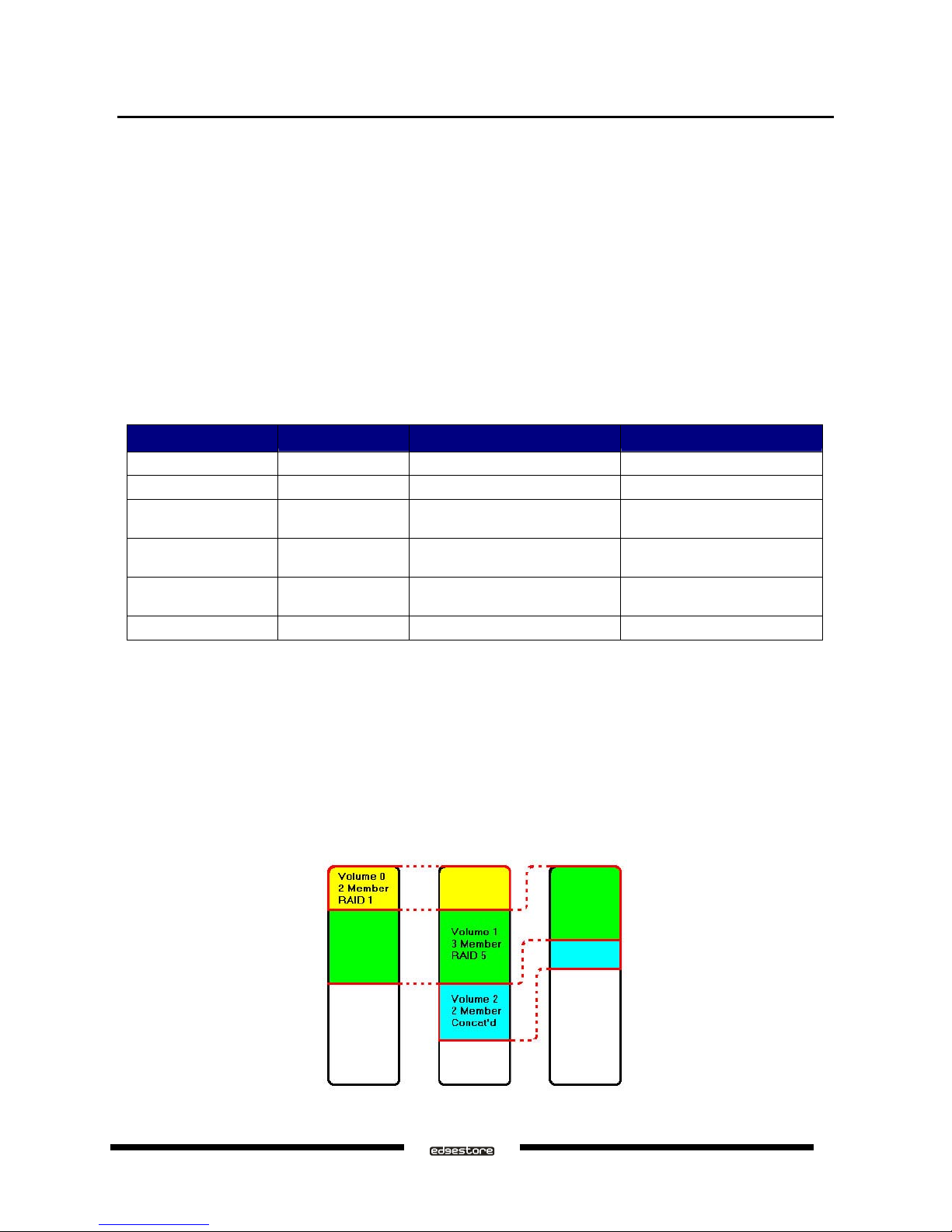
For increased versatility, the SATARAID5 software allows individual disks to be divided into smaller segments
which can then be combined into different volumes. As an example, if a user has one set of data that must
be protected at all costs, another set of data which should be protected at reasonable cost and another set
that
doesn’t need any protection at all; the user can divide three disks into sections as shown in Figure 1. The yellow
regions define the high security v olu me, the greem section is the middle security volume and the light blue shows
the unprotected area.
Figure 1: Dividing Disks into Members
DAS401 User’s Manual
Ver.071015
7
Page 8
2.3 RAID LEVELS
2.3.1 DISK STRIPING (RAID 0)
Striping is a performance-oriented, non-redundant data mapping technique. While Striping is discussed as a
RAID Group type, it is does not provide any fault tolerance. With modern SATA and ATA bus mastering
technology, multiple I/O operations can be performed in parallel, enhancing data throughput. Striping arrays use
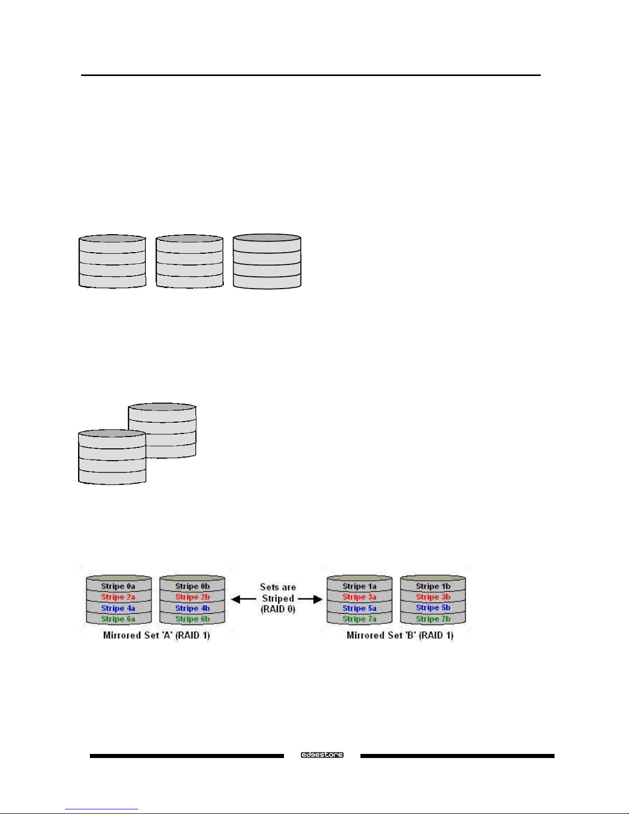
multiple disks to form a larger virtual disk. The figure below illustrates a three-disk stripe set. Stripe one is written
to disk one, stripe two to disk two, and so forth. RAID 0 sets can be comprised of two, three, or four drives. If the
sizes of the disk segments are different, the smallest disk segment will limit the overall size of the RAID Group.
Stripe0 Stripe1 Stripe2
Stripe3 Stripe4 Stripe5
Stripe6
Stripe9
Stripe7
Stripe10
Stripe8
Stripe11
2.3.2 DISK MIRRORING (RAID 1)
Disk mirroring creates an identical twin for a selected disk by having the data simultaneously written to two disks.
This redundancy provides instantaneous protection from a single disk failure. If a read failure occurs on one drive,
the system reads the data from the other drive. RAID 1 sets are comprised of two drives, and a third drive can be
allocated as a spare in case one of the drives in the set fails. If the sizes of the disk segments are different, the
smallest disk segment will limit the overall size of the RAID Group.
Block 0
Block 1
Block 2
Block 3
Block 0
Block 1
Block 2
Block 3
2.3.3 DISK MIRRORING AND STRIPING (RAID 10)
RAID 10 combines the features of both RAID 0 and RAID 1. Performance is provided through the use of Striping
(RAID 0), while adding the fault tolerance of Mirroring (RAID 1). The implementation of RAID 10 requires four
drives. The drives are assigned as two sets of striped pairs.
The data is written to RAID Group A, which is mirrored (RAID 1) a nd provides data redundancy. Alternating
blocks of data are then striped across another RAID 1 mirrored set, shown as Set B in the figure above. This
provides improved speed.
Under certain circumstances, a RAID 10 set can sustain multiple simultaneous drive failures.
Ver.071015
DAS401 User’s Manual
8
Page 9
2.3.4 PARITY RAID (RAID 5)
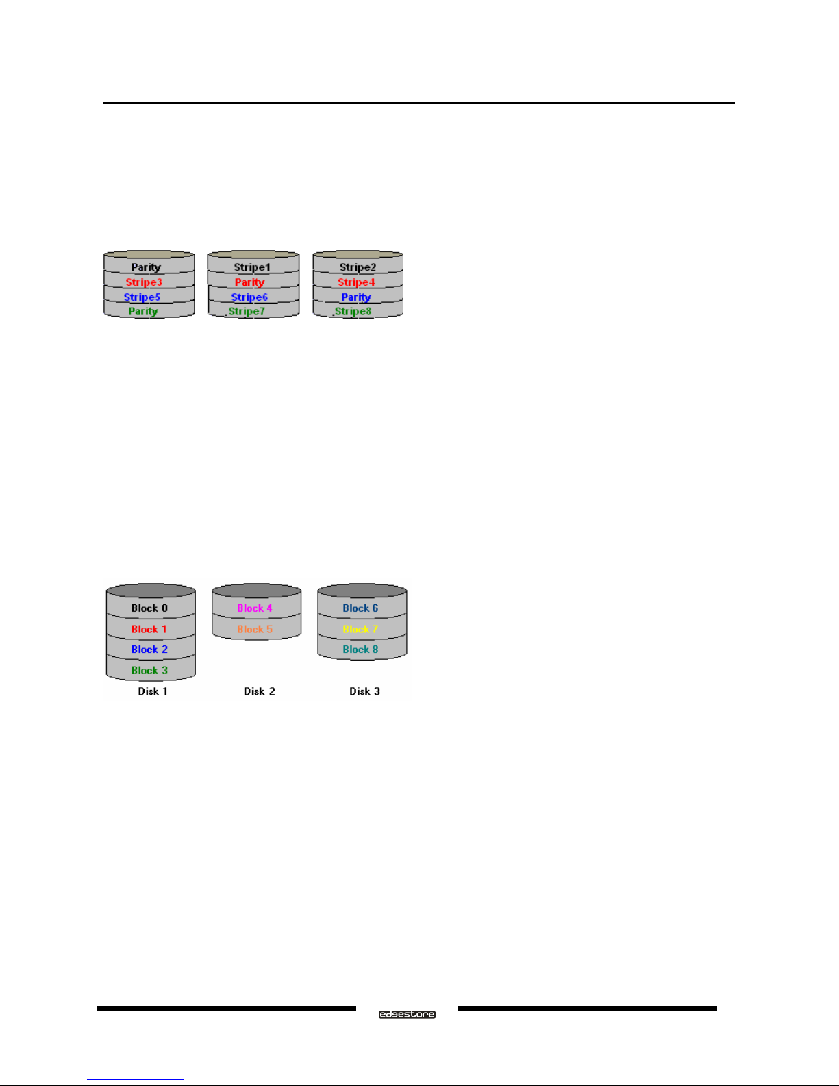
Parity or RAID 5 adds fault tolerance to Disk Striping by including parity information with the data. Parity RAID
dedicates the equivalent of one disk for storing parity stripes. The data and parity information is arranged on the
disk array so that parity is writte n t o diff ere nt dis k s . Ther e are at le a st 3 memb e rs t o a P arit y R AID set. The
following example illustrates how the parity is rotated from disk to disk. The following example illustrates how the
parity is rotated from disk to disk.
Parity RAID uses less capacity for protection and is the preferred method to reduce the cost per megabyte for
larger installations. Mirroring requires 100% increase in capacity to protect the data whereas the above example
using three hard drives only requires a 50% increase. The additional required capacity decreases as the number
of disks in the group increases (i.e., 33% for four drives or 25% for five drives).
In exchange for low overhead necessary to implement protection, Parity RAID degrades performance for all write
operations. The parity calculations for Parity RAID may result in write performance that is somewhat slower than
the write performance to a single disk.
2.3.5 CONCATENATION (COMBINE DRIVE)
The Concatenated mode combines multiple disks or segments of disks into a single large volume. It does not
provide any data protection or performance improvement but can be useful for utilizing leftover space on disks.
Concatenation allows the segments that make up the volume to be of different sizes.
2.3.6 SINGLE DRIVE / SEGMENT
The single drive is a virtual disk that can either be an entire disk drive or a segment of a single disk drive. Single
drive is the “Contiguous” configuration option when creating RAID Groups (or sets) in the SATARAID5 software.
DAS401 User’s Manual
Ver.071015
9
Page 10
2.4 RAID VOLUME STATUS
A RAID volume can be in any one of the following statuses.
STATUS
MEANING
Good All disks are currently functioning as normal.
Reduced
For RAID levels that provide data protection, one or more disks have failed but the data is
still available via the RAID algorithms. The failed disk should be replaced as soon as
possible to avoid loss of data.
Rebuilding
A failed disk drive has been replaced and the data is being regenerated on the replacement
disk. When complete, the RAID Group will return to Good status.
Resynchronizing
An error has occurred and RAID algorithms be regenerated on this RAID Group. When
complete, the RAID Group will return to Good status.
Failed
One or more disks have failed and RAID algorithms can no longer regenerate the data. The
minimum number of failures required to reach this state depends on the RAID level:
a
RAID 0, Concatenated, Contiguous: Single disk failure.
a
RAID 1, 10, and 5: Two disk failure.
Ver.071015
DAS401 User’s Manual
10
Page 11
3 INSTALLATION
3.1 COMPONENTS
There are three separate steps that must be install or setup for DAS401 to function. These components are the
HARDWARE, SATA RAID5 HBA DRIVER, and SATARAID5 Utility. The steps on how to setup these packages
is described in the following sections.
3.2 INSTALLING HARDWARE
Follow the descriptions below, and step by step to complete the installation.
a
Turn off your host computer.
a
Install the SiI3132 PCI-Express 1X SATA RAID5 HBA into a PCI-Express slot (1X ~ 16X), than connect one
end of the eSATA cable to the eSATA connector on the Sil3132 PCI-Express 1X SATA RAID5 HBA.
a
Connect the other end to the eSATA connecter on DAS401.
a
If hard disk drives are not installed in DAS401, insert the drives most of the way into bay 1 to
4 in order (from the bottom to top); gently insert the drive until the drive is fully inserted, and twist the toolless screw shut to seat the drive securely.
a
Switch the VAC to the correct position (For example, 115 for Japan, and 230 for UK) attach one end of the
AC power cord to DAS401 and the other end to the proper AC receptacle.
a
Turn on DAS401, than turn on the host computer.
3.3 INSTALLING ON WINDOWS 2000
3.3.1 INSTALLING SATA RAID HOST BUS ADAPTER
Follow the descriptions below, and step by step to complete the setup.
a
Insert the Setup and Installation Driver Repository CD in the CD-ROM drive.
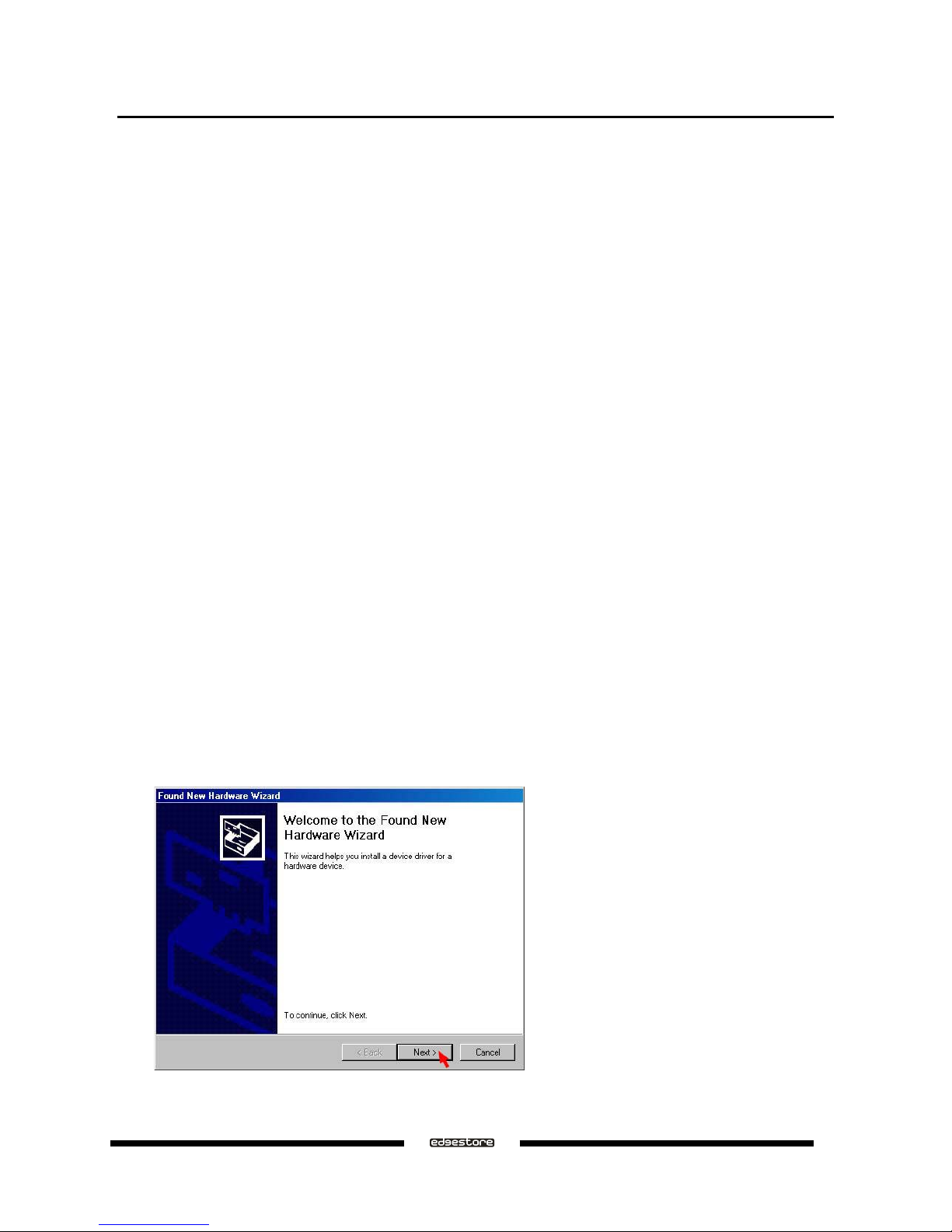
a
When start the Windows O/S, new hardware will be found, click Next.
DAS401 User’s Manual
Ver.071015
11
Page 12
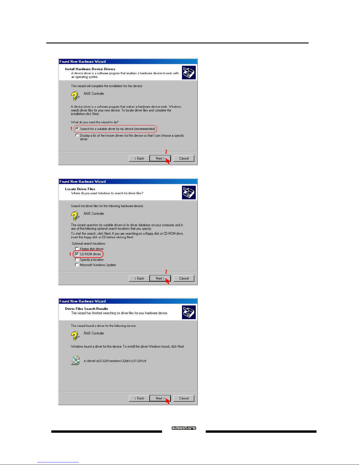
a
Select Search for a suitable driver for my device (recommended), than click Next.
a
Select CD-ROM drives, than click Next.
a
Click Next to search the driver of RAID Controller.
Ver.071015
DAS401 User’s Manual
12
Page 13
a
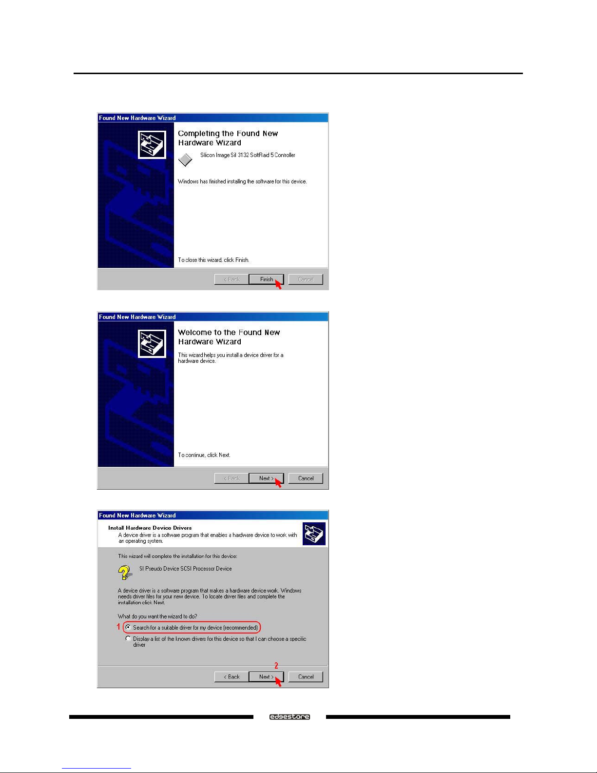
When the RAID Controller installation has completed, click Finish, and begin to the Pseudo SCSI
Processor Device installation.
a
Windows will find the Pseudo SCSI Processor Device hardware, click Next.
a
Select Search for a suitable driver for my device (recommended), than click Next.
DAS401 User’s Manual
Ver.071015
13
Page 14
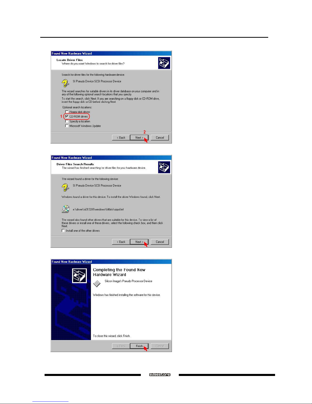
a
Select CD-ROM drives, than click Next.
a
Click Next to install the Pseudo SCSI Processor Device driver.
a
When the Pseudo SCSI Processor Device installation has completed, click Finish.
Ver.071015
DAS401 User’s Manual
14
Page 15
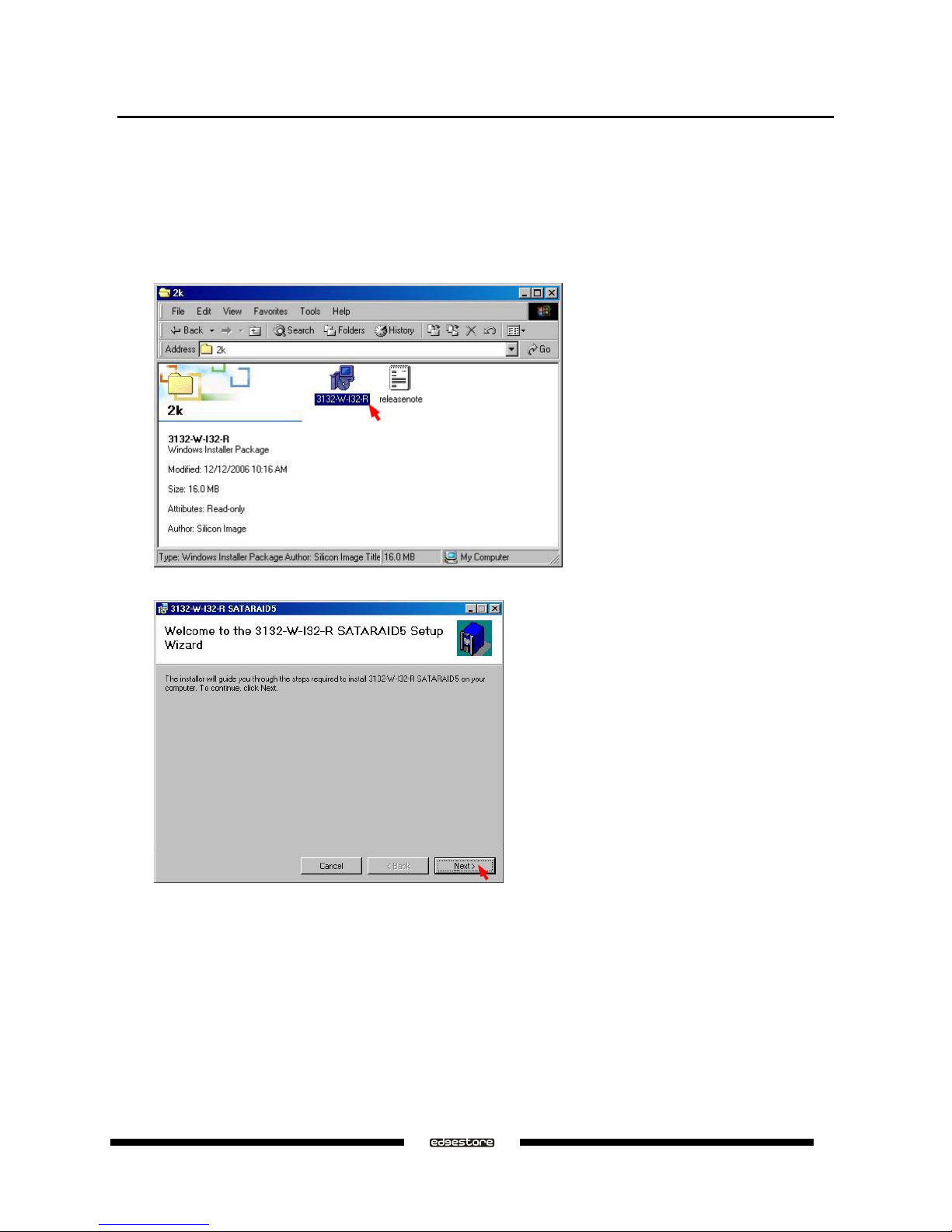
3.3.2 INSTALLING SATARAID5 UTILITY
Follow the descriptions below, and step by step to complete the installation.
a
Open the Setup and Installation Driver Repository CD and select the SATARAID5 Array Manager software
from the Utility folder.
a
Double-click the 3132-W-I32-R.msi file (Located at: E:\ Utility\SiI3132R5\Windows\2k\3132-W-I32-R.msi; PS:
"E:" = CD-ROM drive letter).
a
Click Next to begin setup.
DAS401 User’s Manual
Ver.071015
15
Page 16
a
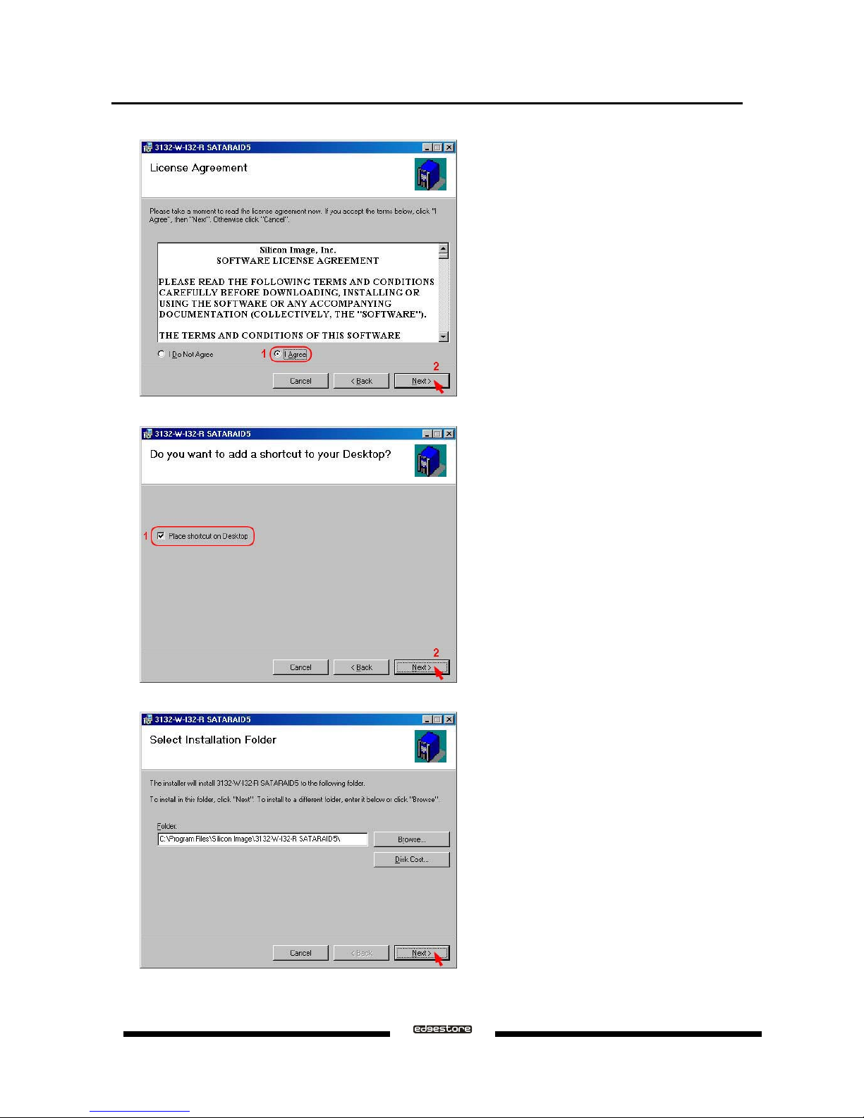
Select I Agree, than click Next.
a
Select Place shortcut on Desktop, than click Next.
a
Click Next to use the default installation folder.
Ver.071015
DAS401 User’s Manual
16
Page 17
a
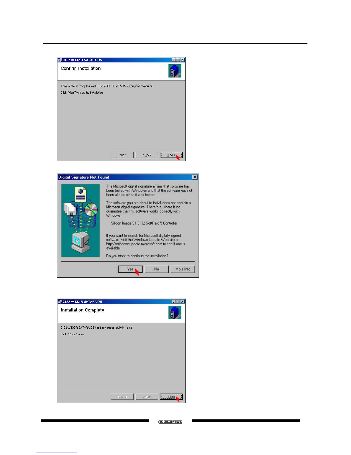
Click Next to begin the installation.
a
When Digital Signature Not Found message pop-out, click Yes to continue the installation.
a
When the SATARAID5 Utility installation has completed, click Close, and begin to the Java platform
installation.
DAS401 User’s Manual
Ver.071015
17
Page 18
a
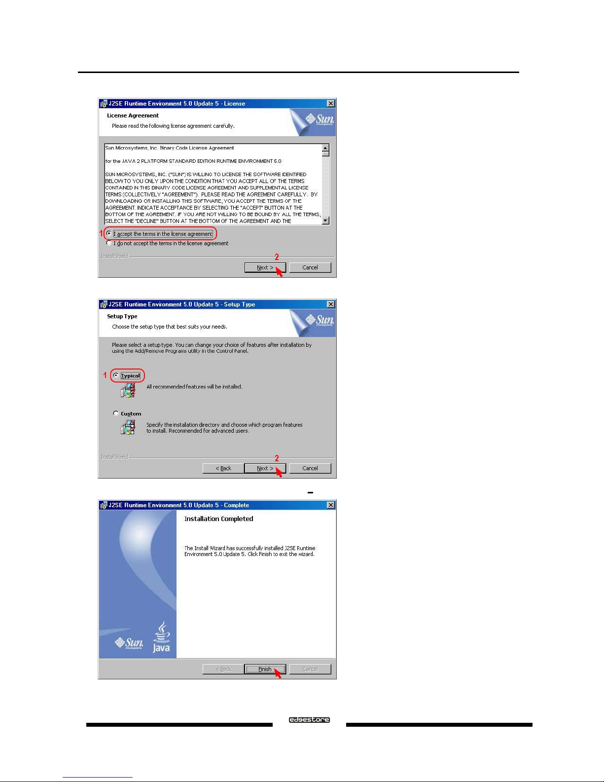
Select I accept the terms in the license agreement, than click Next.
a
Select Typical, than click Next.
a
When Java platform installation has completed, click Finish to exit.
a
Select Start > Programs > Silicon Image > SATARaid5Manager to start the Array Manager software.
Ver.071015
DAS401 User’s Manual
18
Page 19
3.3.3 DISK DRIVE MODE SETUP
Please refer to the chapter 4.
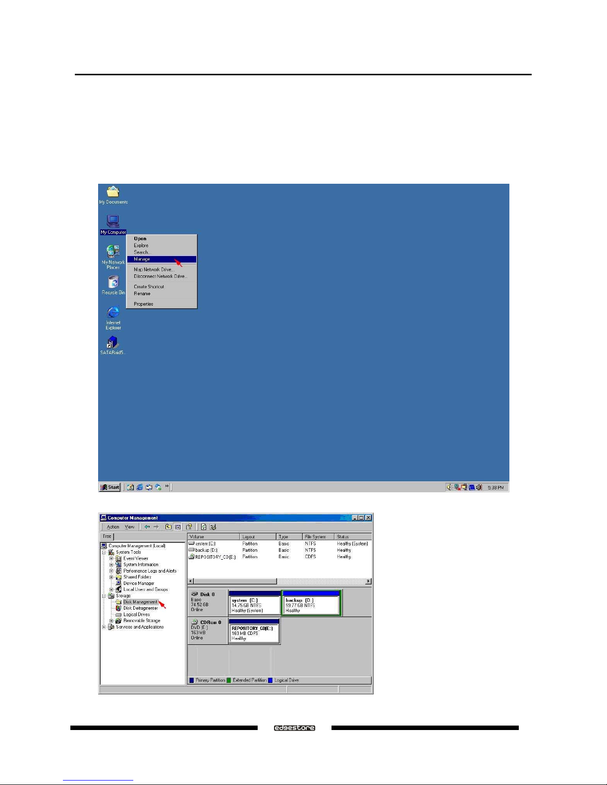
3.3.4 ALLOCATING PARTITION
Before creating any partitions, RAID groups must first be created using the SATARaid5Manager utility. Once the
sets have been created, allow the system to load Windows.
a
Right-click on My Computer icon and select Manage from the pop-up menu.
a
Select Disk Management under Storage to view the disk drives.
DAS401 User’s Manual
Ver.071015
19
Page 20

a
When Write Signature and Upgrade Disk Wizard appears, click Next.
a
Select the new disk to write a signature, than click Next.
a
Do not click any disk to upgrade to dynamic disk, than click Next.
Ver.071015
DAS401 User’s Manual
20
Page 21
a
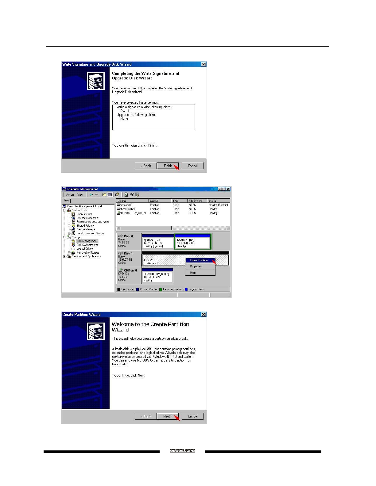
When the Write Signature and Upgrade Disk Wizard has completed, click Finish.
a
Right-click on the Unallocated partition and select Create Partition… from the pop-up menu.
a
Click Next to create a partition on a basic disk.
DAS401 User’s Manual
Ver.071015
21
Page 22
a
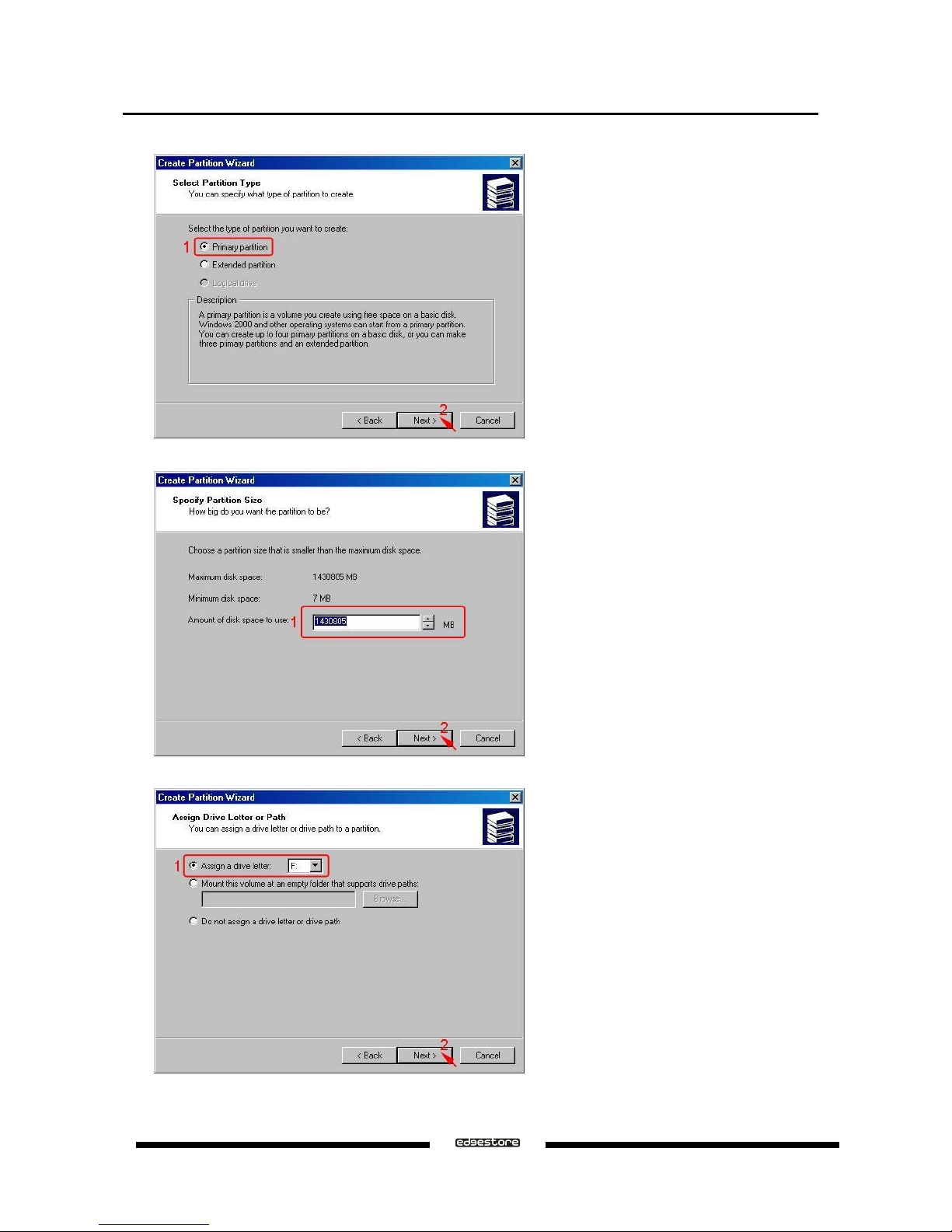
Select the partition type you want to create, than click Next.
a
Specify the partition size you want to create, than click Next.
a
Assign the drive letter or path you want to create, than click Next.
Ver.071015
DAS401 User’s Manual
22
Page 23
a
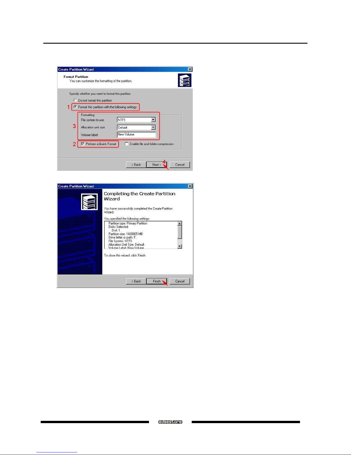
Click Format this partition with the following settings and Perform a Quick Format, setup the File
system to use, Allocation unit size, Volume label, than click Next.
a
When the Create Partition Wizard has completed, click Finish.
DAS401 User’s Manual
Ver.071015
23
Page 24
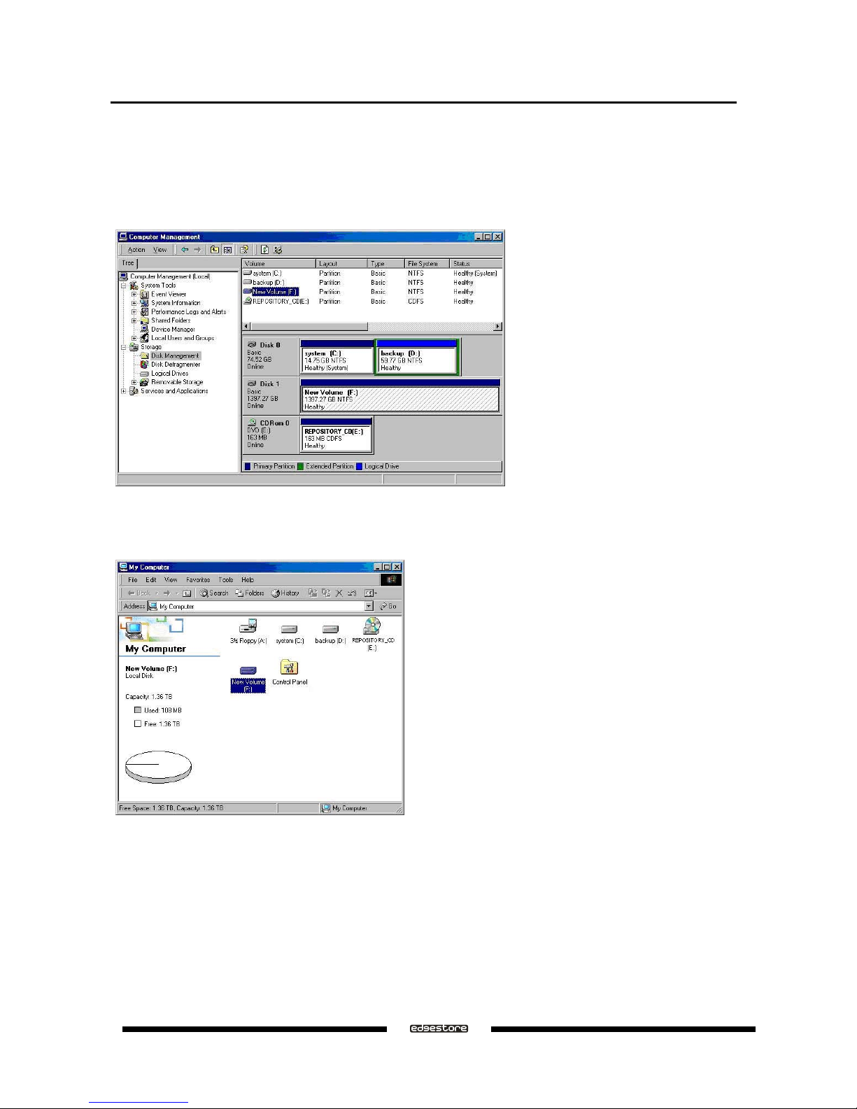
The status of the newly created partition in the Disk Management window should change to Formatting and the
percentage complete will be displayed. Depending upon the size of the partition, the format process may take
several minutes. When complete, the status will change to “Healthy" and the name and drive letter will be
updated. Once the disk reports Healthy, it appears in the listing in System Listing section with all of its pertinent
information as well.
Repeat the above procedure as needed for any other partitions. Close the Data Management window by
clicking on the small boxed “X” in the top right corner of the window. Click on the “My Computer” icon on the
Desktop. The new drives will be visible and properly named. The new disks are available for use.
Ver.071015
DAS401 User’s Manual
24
Page 25
3.4 INSTALLING ON WINDOWS XP
3.4.1 INSTALLING SATA RAID HOST BUS ADAPTER
Follow the descriptions below, and step by step to complete the setup.
a
Insert the Setup and Installation Driver Repository CD in the CD-ROM drive.
a
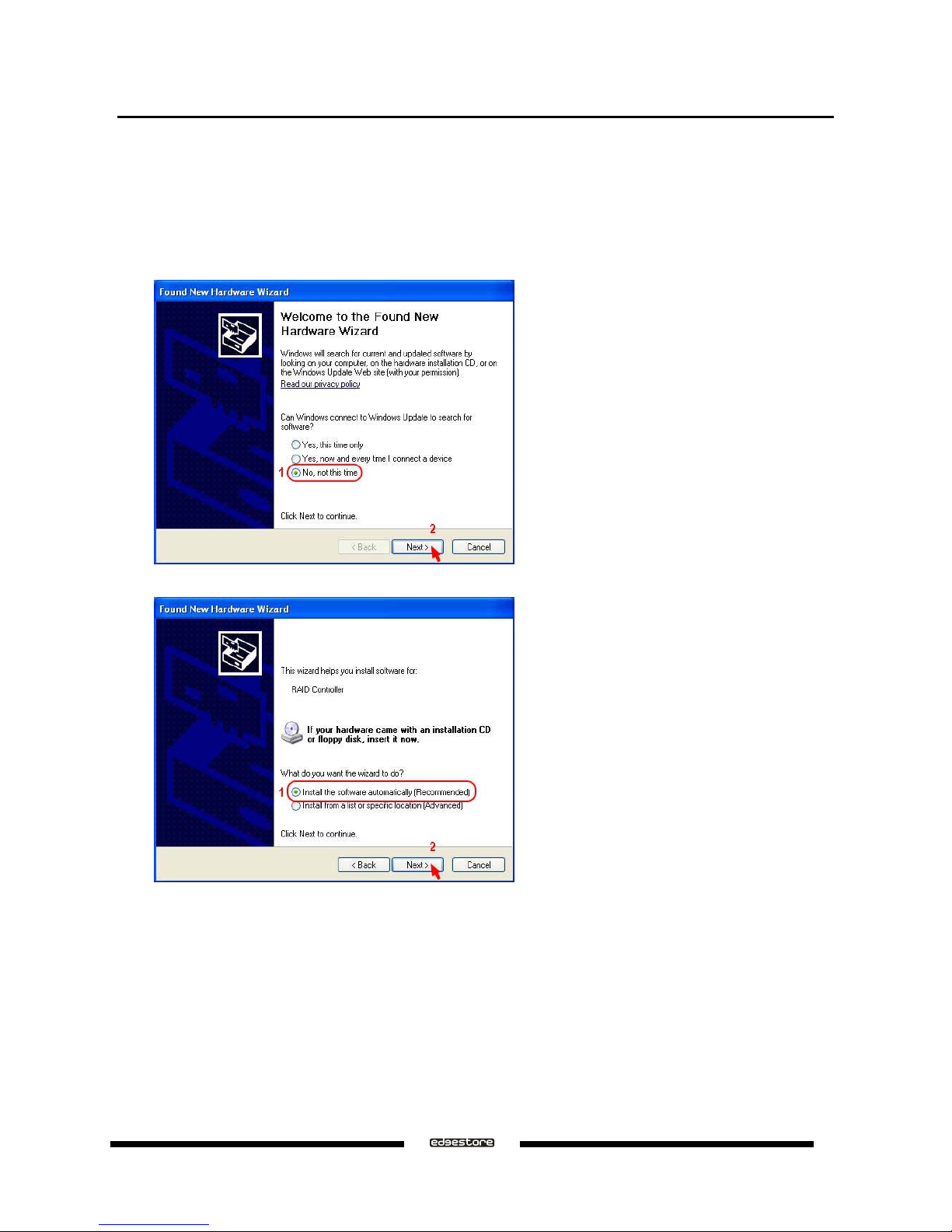
When start the Windows O/S, new hardware will be found; Select No, not this time, than click Next.
a
Select Install the software automatically (Re co mmended), than click Next.
DAS401 User’s Manual
Ver.071015
25
Page 26
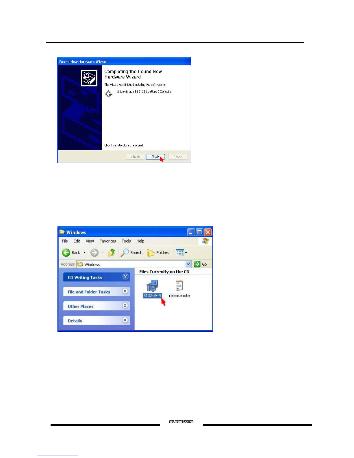
a
When the installation has completed, click Finish.
3.4.2 INSTALLING SATARAID5 UTILITY
Follow the descriptions below, and step by step to complete the installation.
a
Open the Setup and Installation Driver Repository CD and select the SATARAID5 Array Manager software
from the Utility folder.
a
Double-click the 3132-W-R.msi file (Located at: E:\Utility\SiI3132R5\Windows\3132-W-R.msi; PS: "E:" =
CD-ROM drive letter).
Ver.071015
DAS401 User’s Manual
26
Page 27
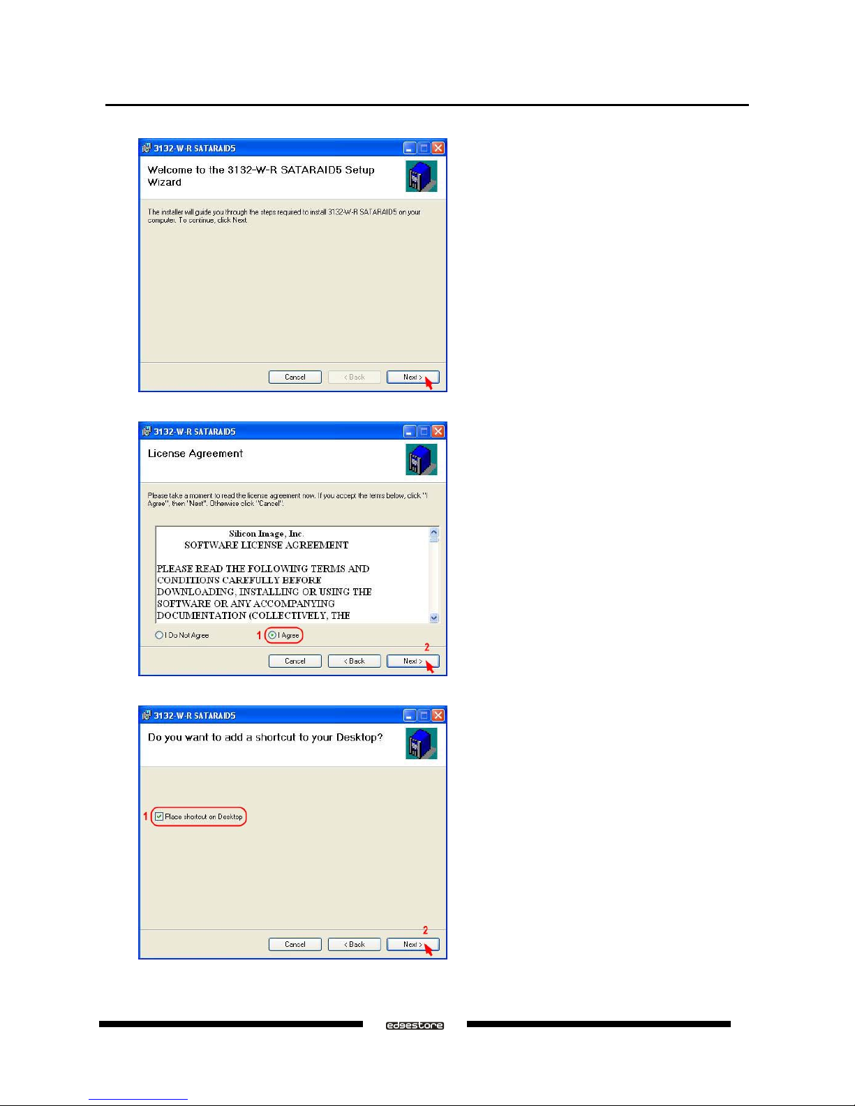
a
Click Next to begin setup.
a
Select I Agree, than click Next.
a
Select Place shortcut on Desktop, than click Next to create a shortcut on the desktop.
DAS401 User’s Manual
Ver.071015
27
Page 28
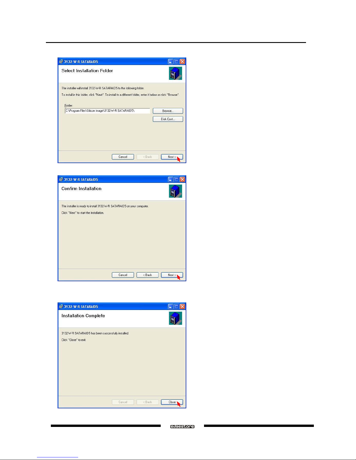
a
Click Next to use the default installation folder.
a
Click Next to begin the installation.
a
When the SATARAID5 Utility installation has completed, click Close, and begin to the Java platform
installation.
Ver.071015
DAS401 User’s Manual
28
Page 29
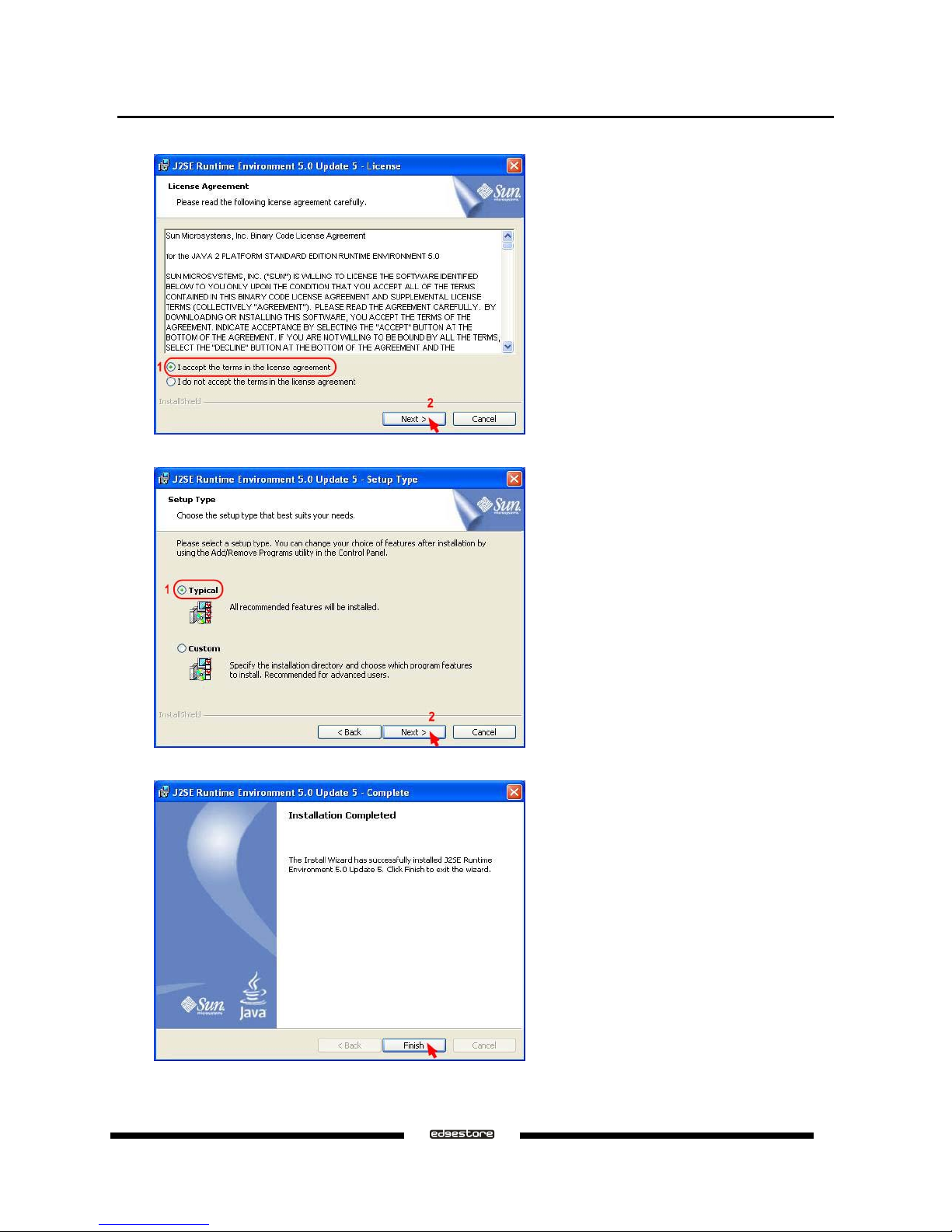
a
Select I accept the terms in the license agreement, than click Next.
a
Select Typical, than click Next.
a
When Java platform installation has completed, click Finish to exit.
a
Select Start > All Programs > Silicon Image > SATARaid5Manager to start the Array Manager software.
DAS401 User’s Manual
Ver.071015
29
Page 30
3.4.3 DISK DRIVE MODE SETUP
Please refer to the chapter 4.
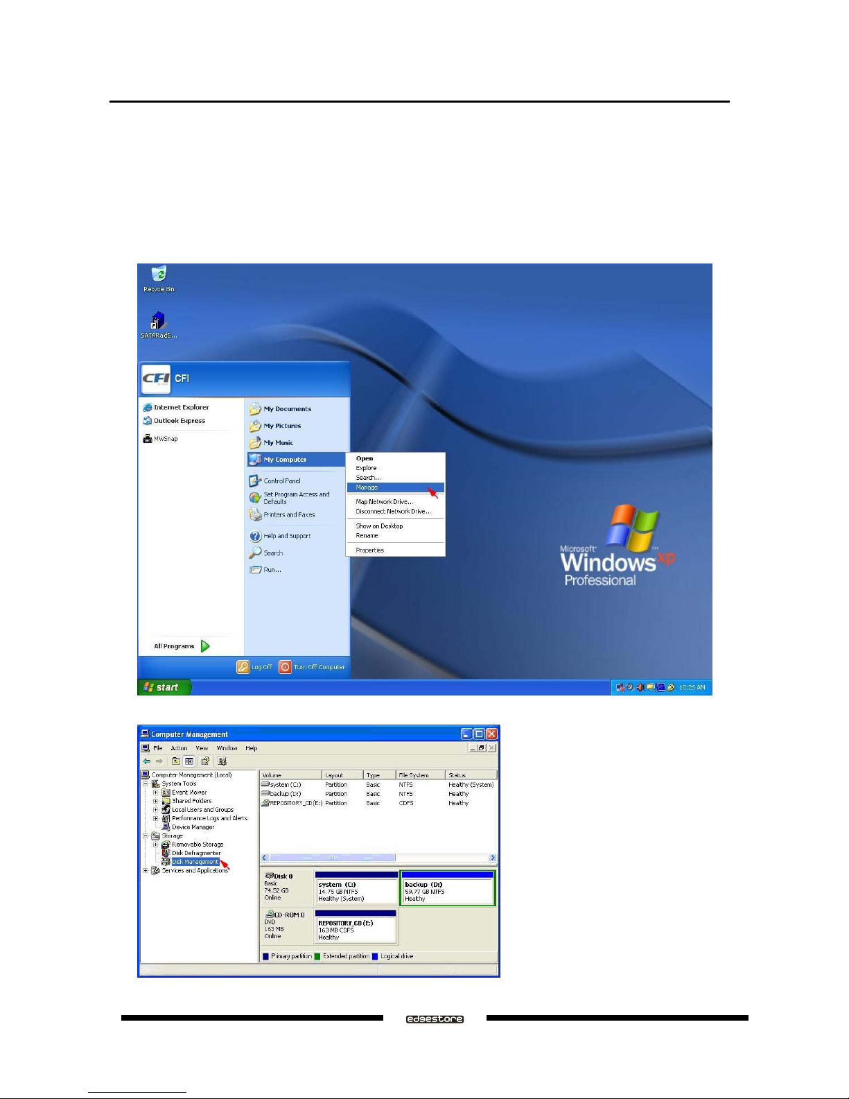
3.4.4 ALLOCATING PARTITIONS ON WINDOWS XP 32-BIT
Before creating any partitions, RAID groups must first be created using the SATARaid5Manager utility. Once the
sets have been created, allow the system to load Windows.
a
Right-click on My Computer icon and select Manage from the pop-up menu.
a
Select Disk Management under Storage to view the disk drives.
Ver.071015
DAS401 User’s Manual
30
Page 31
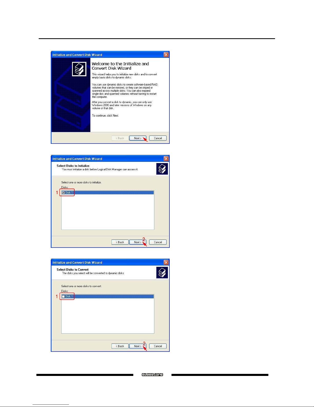
a
When Initialize and Convert Disk Wizard appears, click Next.
a
Select the new disk to initialize, than click Next.
a
Do not click any disk to convert, than click Next.
DAS401 User’s Manual
Ver.071015
31
Page 32
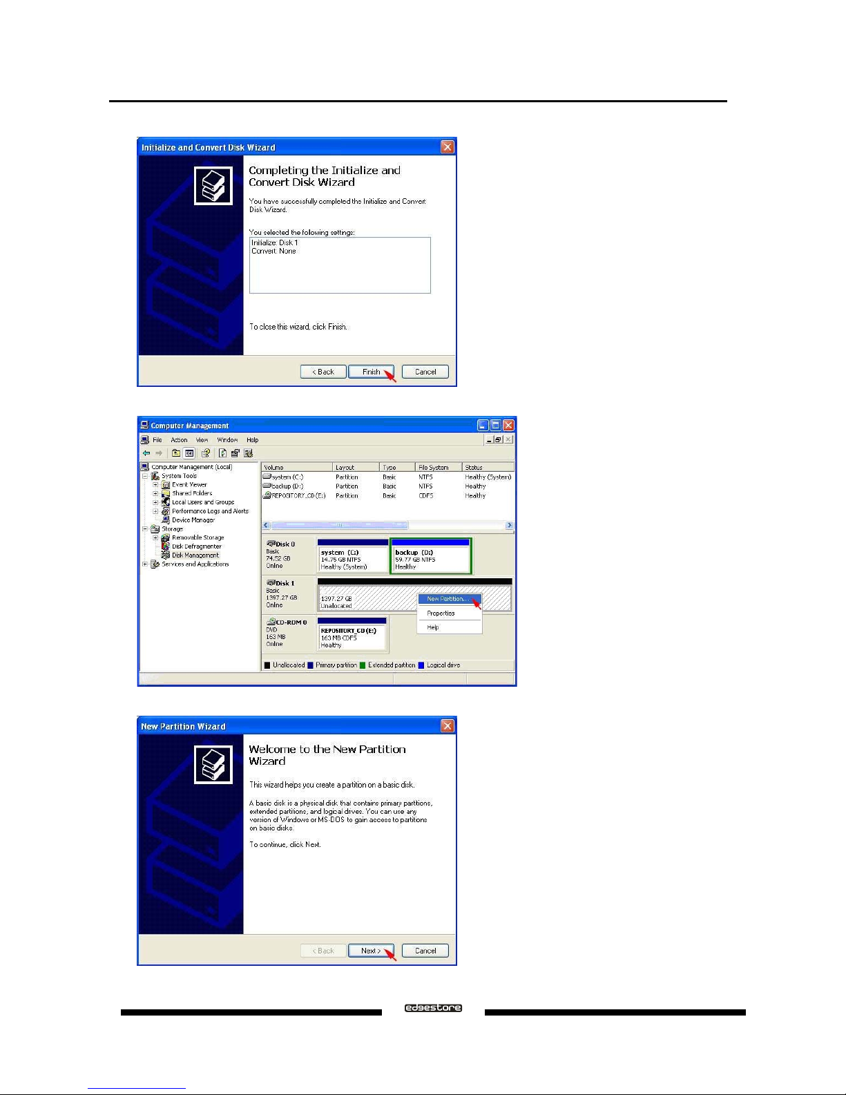
a
When the Initialize and Convert Disk Wizard has completed, click Finish.
a
Right-click on the Unallocated partition and select New Partition… from the pop-up menu.
a
Click Next to create a partition on a basic disk.
Ver.071015
DAS401 User’s Manual
32
Page 33
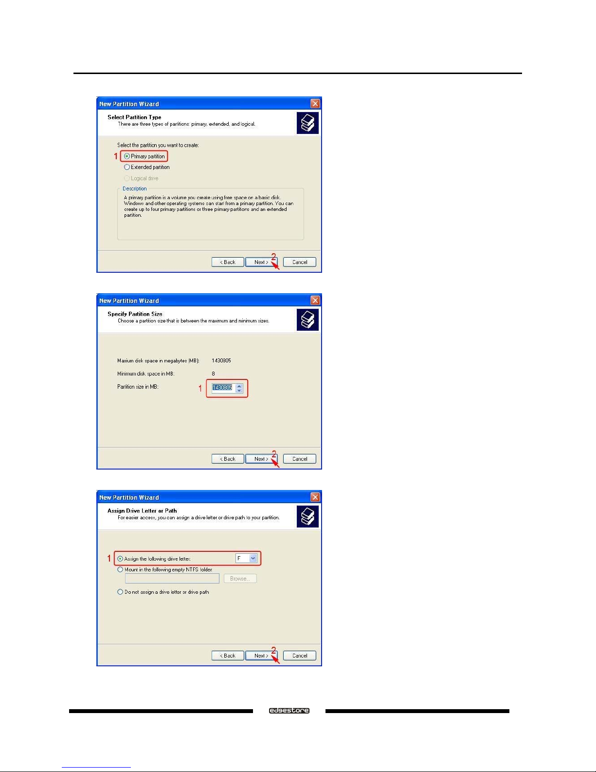
a
Select the partition type you want to create, than click Next.
a
Specify the partition size you want to create, than click Next.
a
Assign the drive letter or path you want to create, than click Next.
DAS401 User’s Manual
Ver.071015
33
Page 34
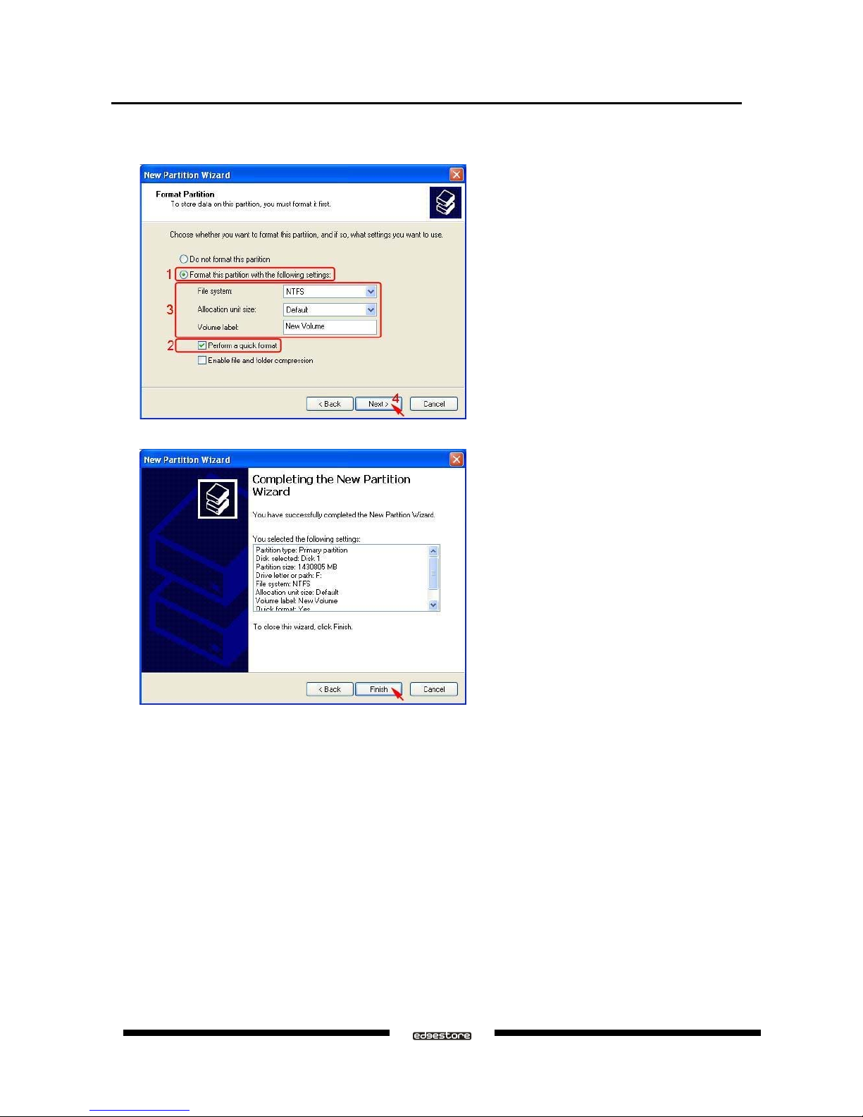
a
Click Format this partition with the following settings and Perform a quick format, setup the File
system, Allocation unit size, Volume label, than click Next.
a
When the New Partition Wizard has completed, click Finish.
Ver.071015
DAS401 User’s Manual
34
Page 35
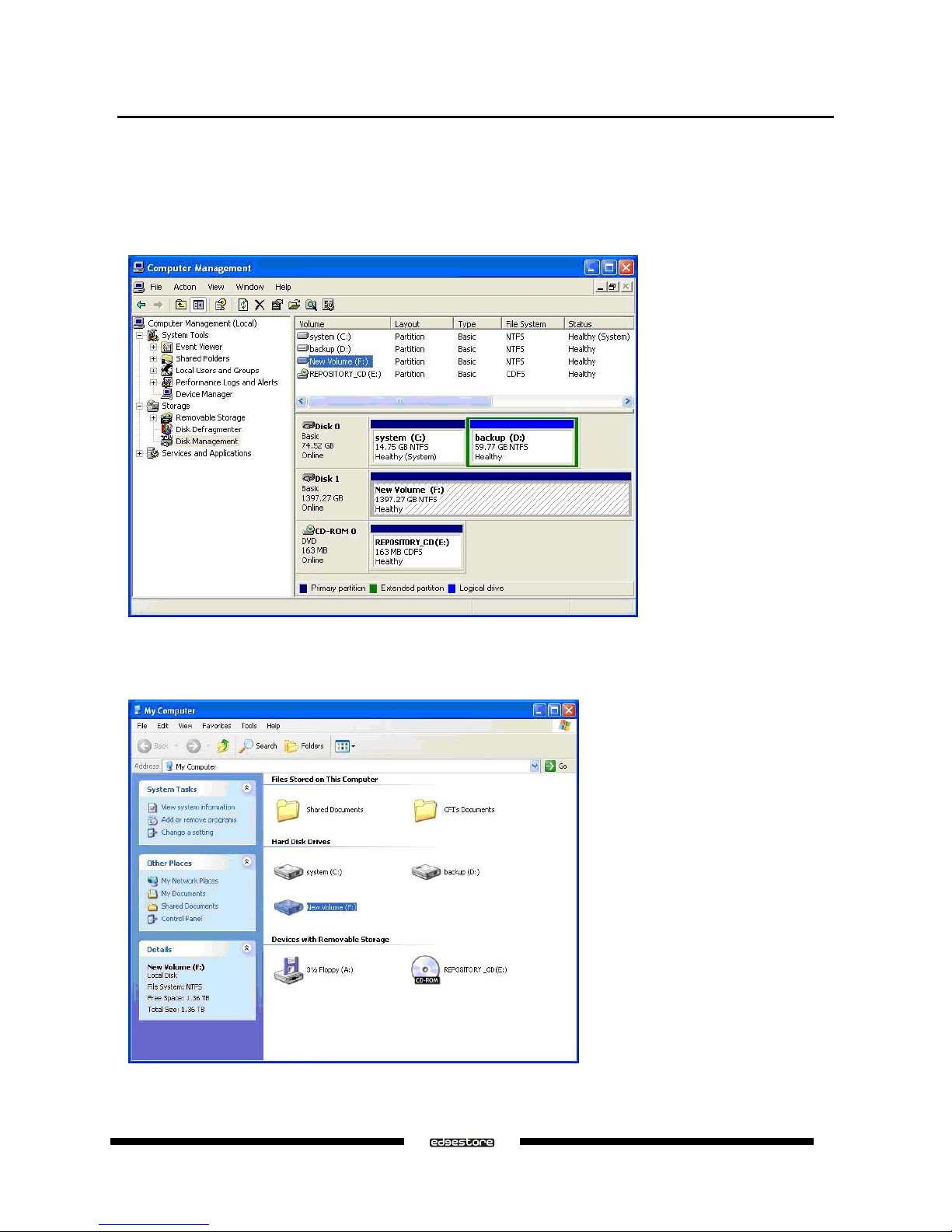
The status of the newly created partition in the Disk Management window should change to Formatting and the
percentage complete will be displayed. Depending upon the size of the partition, the format process may take
several minutes. When complete, the status will change to “Healthy" and the name and drive letter will be
updated. Once the disk reports Healthy, it appears in the listing in System Listing section with all of its pertinent
information as well.
Repeat the above procedure as needed for any other partitions. Close the Data Management window by
clicking on the small boxed “X” in the top right corner of the window. Click on the “My Computer” icon on the
Desktop. The new drives will be visible and properly named. The new disks are available for use.
DAS401 User’s Manual
Ver.071015
35
Page 36
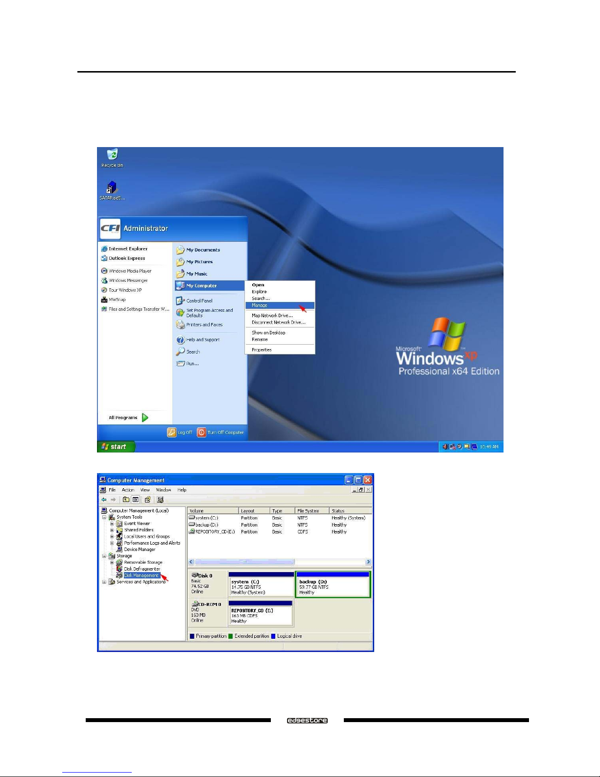
3.4.5 ALLOCATING PARTITIONS ON WINDOWS XP 64-BIT
Before creating any partitions, RAID groups must first be created using the SATARaid5Manager utility. Once the
sets have been created, allow the system to load Windows.
a
Right-click on My Computer icon and select Manage from the pop-up menu.
a
Select Disk Management under Storage to view the disk drives.
Ver.071015
DAS401 User’s Manual
36
Page 37
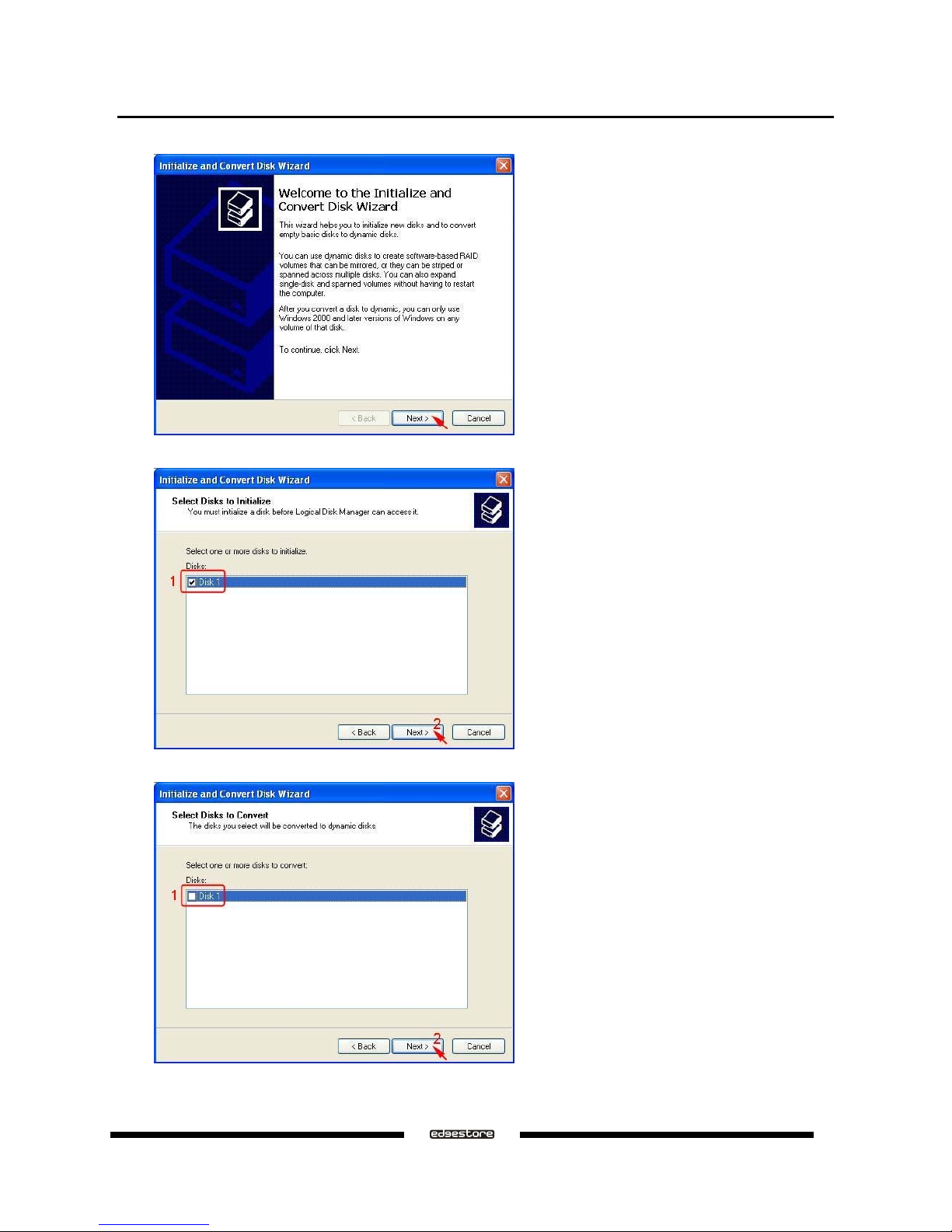
a
When Initialize and Convert Disk Wizard appears, click Next.
a
Select the new disk to initialize, than click Next.
a
Do not click any disk to convert, than click Next.
DAS401 User’s Manual
Ver.071015
37
Page 38
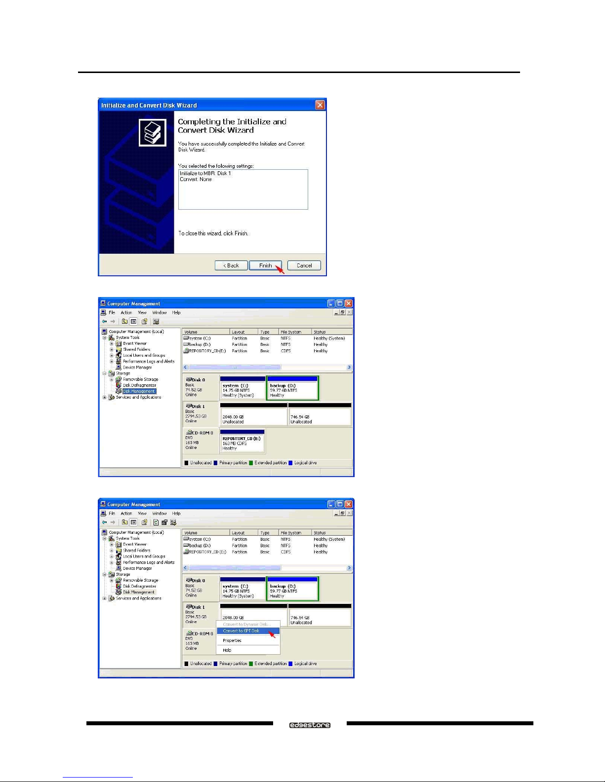
a
When the Initialize and Convert Disk Wizard has completed, click Finish.
a
Windows 64-bit system supports GPT disk which supports disk volume greater than 2TB.
a
Right-click on the Basic disk and select Convert to GPT disk from the pop-up menu.
Ver.071015
DAS401 User’s Manual
38
Page 39
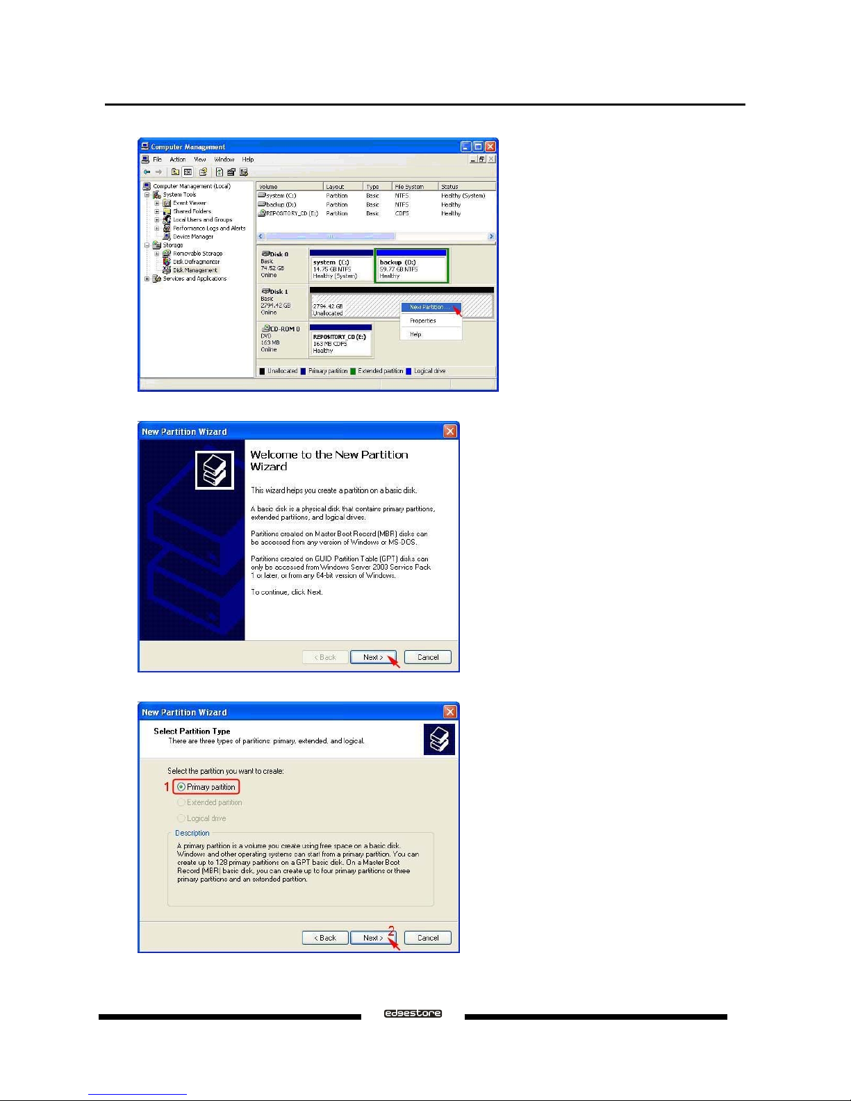
a
Right-click on the Unallocated partition and select New Partition… from the pop-up menu.
a
Click Next to create a partition on a basic disk.
a
Select the partition to create, than click Next.
DAS401 User’s Manual
Ver.071015
39
Page 40
a
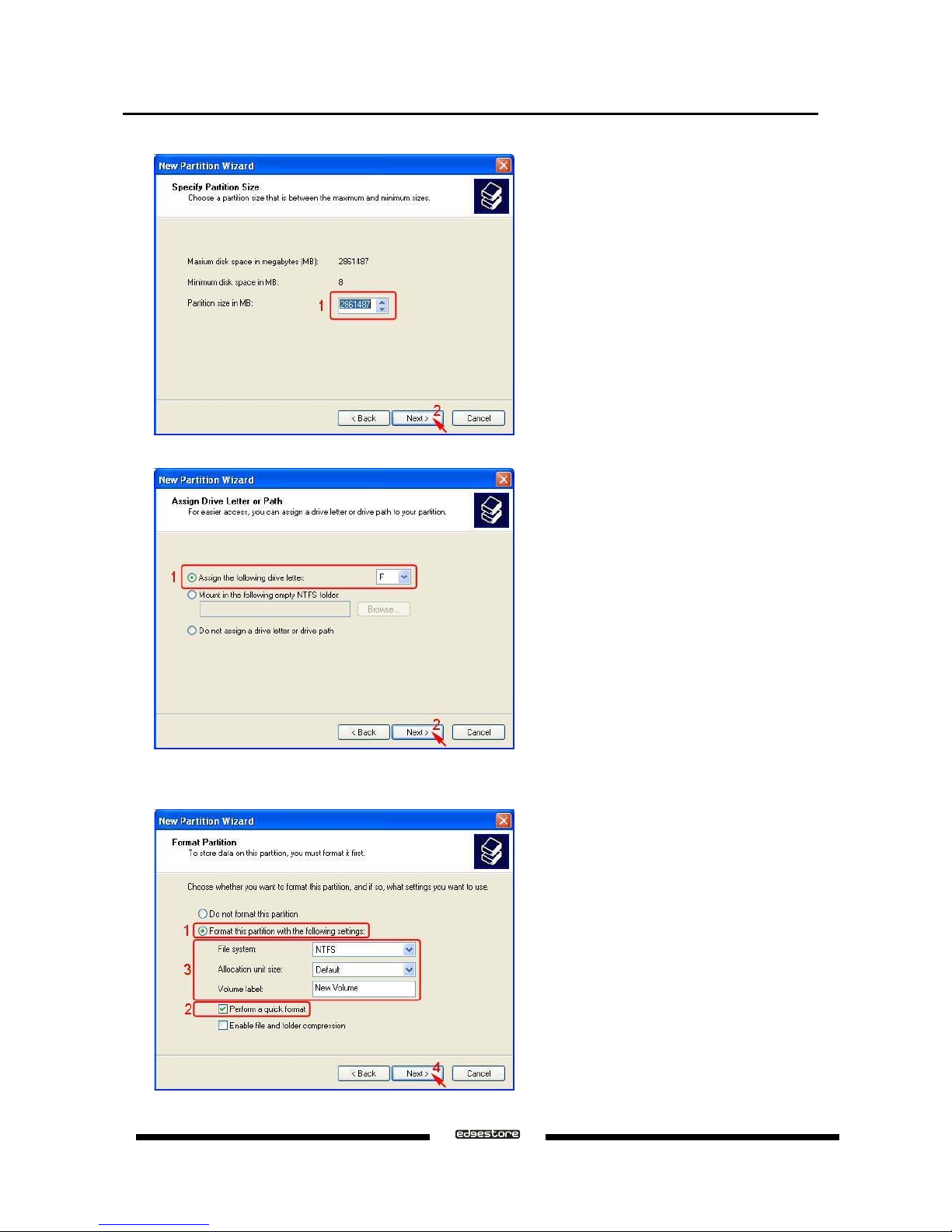
Specify the partition size you want to create, than click Next.
a
Assign the drive letter or path you want to create, than click Next.
a
Click Format this partition with the following settings and Perform a quick format, setup the File
system, Allocation unit size, Volume label, than click Next.
Ver.071015
DAS401 User’s Manual
40
Page 41
a
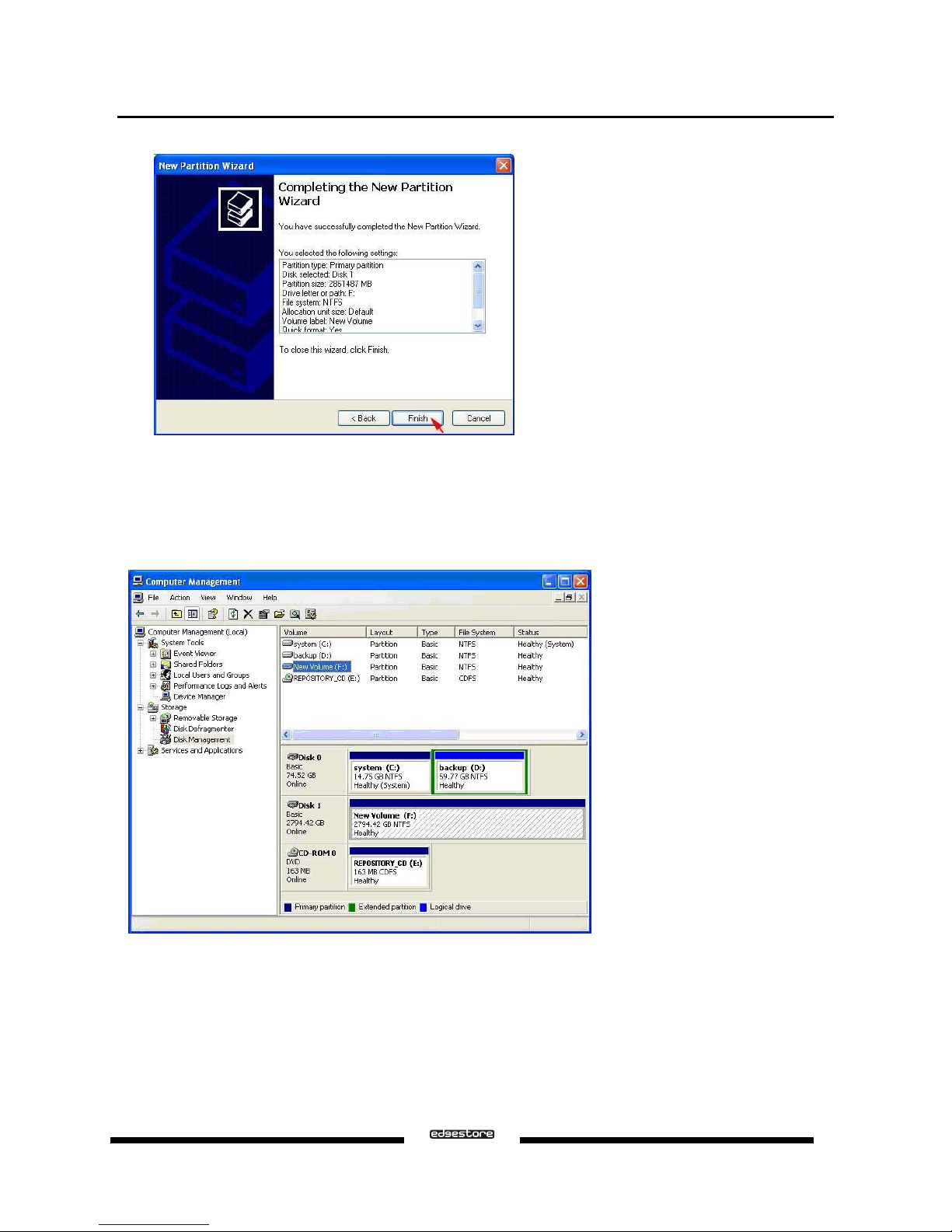
When the New Partition Wizard has completed, click Finish.
The status of the newly created partition in the Disk Management window should change to Formatting and the
percentage complete will be displayed. Depending upon the size of the partition, the format process may take
several minutes. When complete, the status will change to “Healthy" and the name and drive letter will be
updated. Once the disk reports Healthy, it appears in the listing in System Listing section with all of its pertinent
information as well.
DAS401 User’s Manual
Ver.071015
41
Page 42
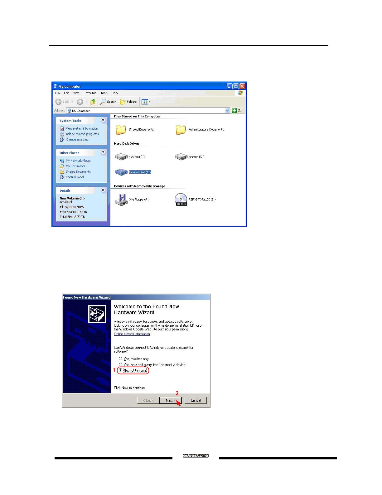
Repeat the above procedure as needed for any other partitions. Close the Data Management window by
clicking on the small boxed “X” in the top right corner of the window. Click on the “My Computer” icon on the
Desktop. The new drives will be visible and properly named. The new disks are available for use.
3.5 INSTALLING ON WINDOWS SERVER 2003
3.5.1 INSTALLING SATA RAID HOST BUS ADAPTER
Follow the descriptions below, and step by step to complete the setup.
a
Insert the Setup and Installation Driver Repository CD in the CD-ROM drive.
a
When start the Windows O/S, new hardware will be found; Select No, not this time, than click Next.
Ver.071015
DAS401 User’s Manual
42
Page 43
a
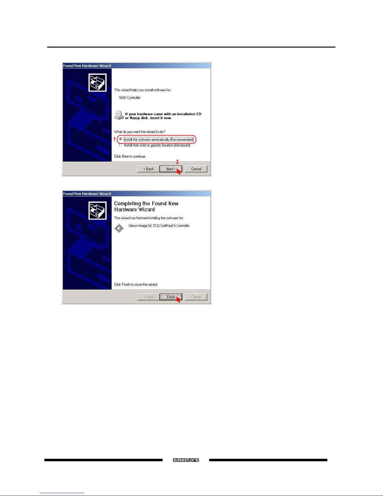
Select Install the software automatically (Re co mmended), than click Next.
a
When the installation has completed, click Finish.
DAS401 User’s Manual
Ver.071015
43
Page 44
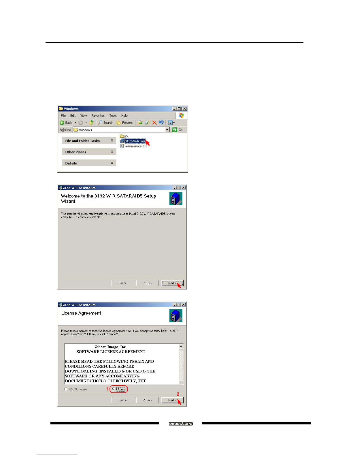
3.5.2 INSTALLING SATARAID5 UTILITY
Follow the descriptions below, and step by step to complete the installation.
a
Open the Setup and Installation Driver Repository CD and select the SATARAID5 Array Manager software
from the Utility folder.
a
Double-click the 3132-W-R.msi file (Located at: E:\Utility\SiI3132R5\Windows\3132-W-R.msi; PS: "E:" =
CD-ROM drive letter).
a
Click Next to begin setup.
a
Select I Agree, than click Next.
Ver.071015
DAS401 User’s Manual
44
Page 45
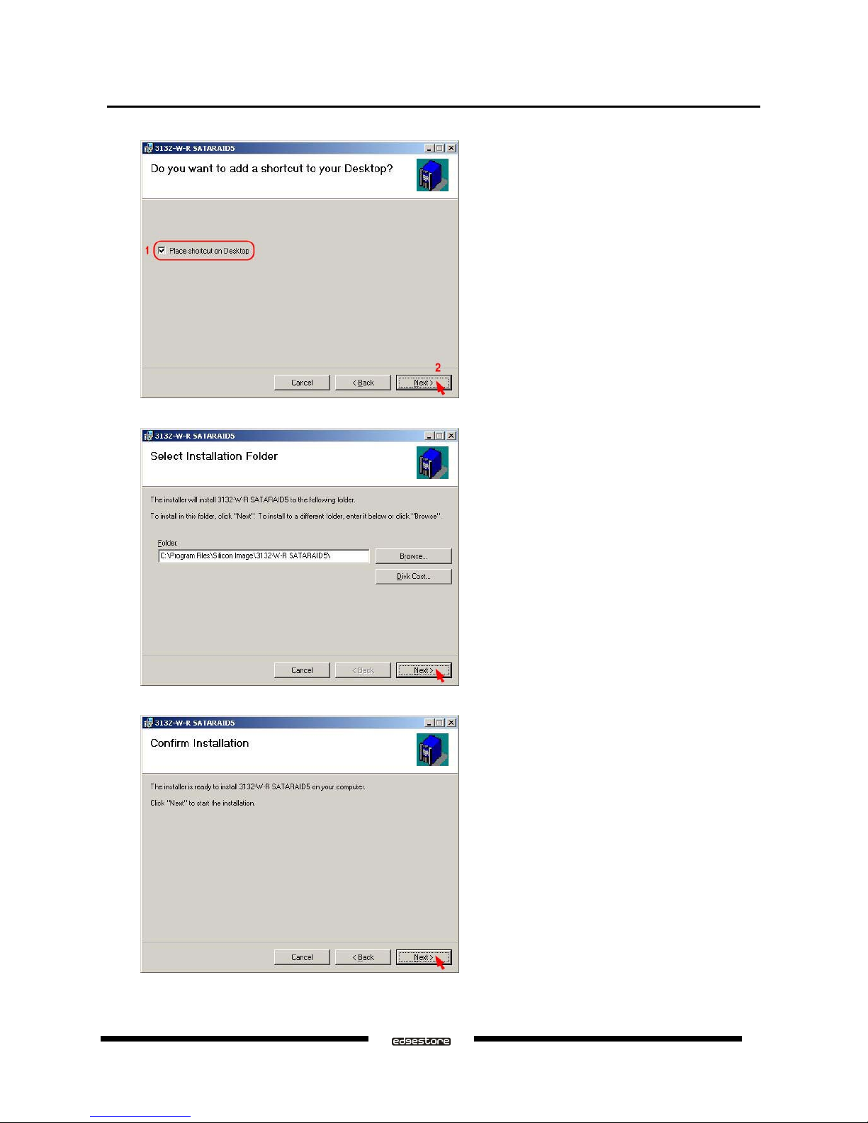
a
Select Place shortcut on Desktop, than click Next to create a shortcut on the desktop.
a
Click Next to use the default installation folder.
a
Click Next to begin the installation.
DAS401 User’s Manual
Ver.071015
45
Page 46
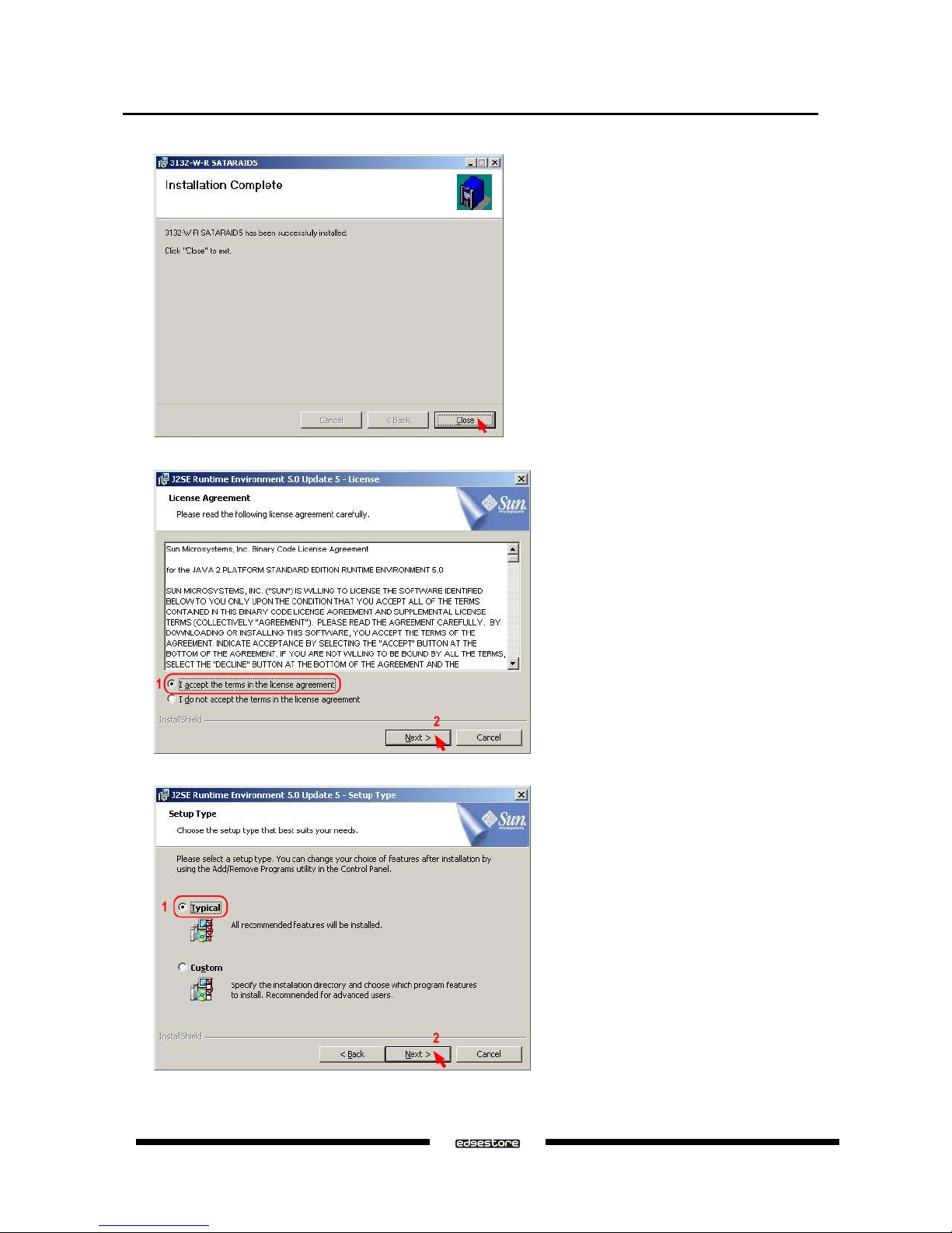
a
When the SATARAID5 Utility installation has completed, click Close, and begin to the Java installation.
a
Select I accept the terms in the license agreement, than click Next.
a
Select Typical, than click Next.
Ver.071015
DAS401 User’s Manual
46
Page 47
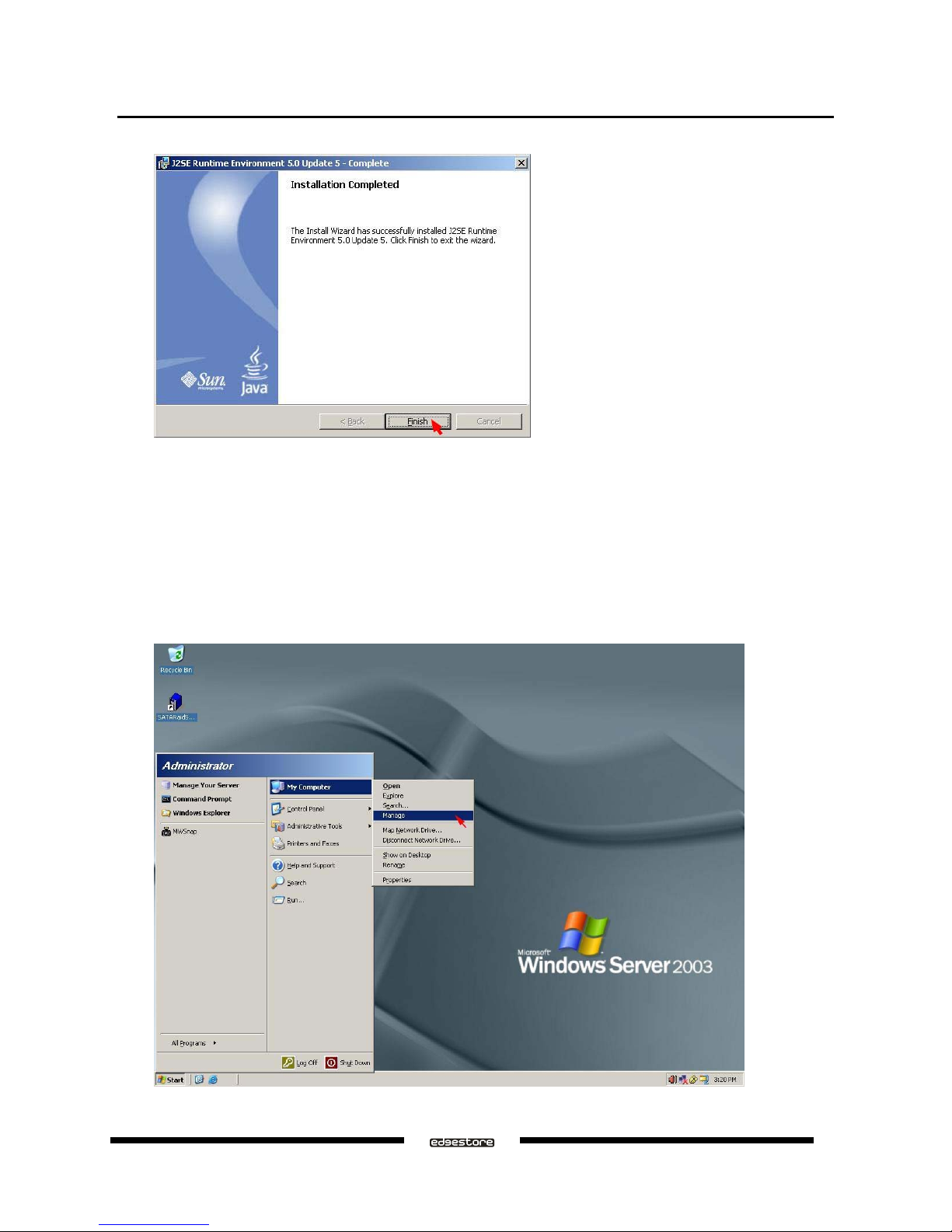
a
When Java platform installation has completed, click Finish to exit.
a
Select Start > All Programs > Silicon Image > SATARaid5Manager to start the Array Manager software.
3.5.3 DISK DRIVE MODE SETUP
Please refer to the chapter 4.
3.5.4 ALLOCATING PARTITIONS
Before creating any partitions, RAID groups must first be created using the SATARaid5Manager utility. Once the
sets have been created, allow the system to load Windows.
a
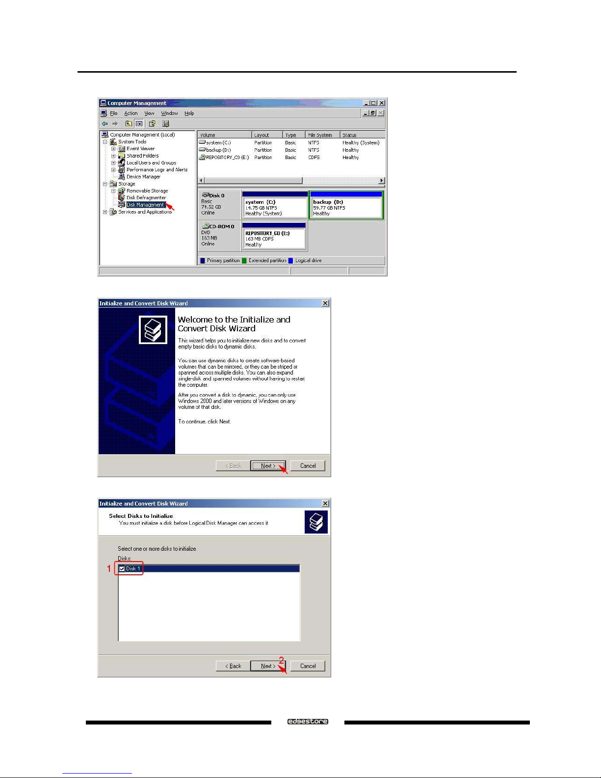
Right-click on My Computer icon and select Manage from the pop-up menu.
DAS401 User’s Manual
Ver.071015
47
Page 48
a
Select Disk Management under Storage to view the disk drives.
a
When Initialize and Convert Disk Wizard appears, click Next.
a
Select the new disk to initialize, than click Next.
Ver.071015
DAS401 User’s Manual
48
Page 49
a
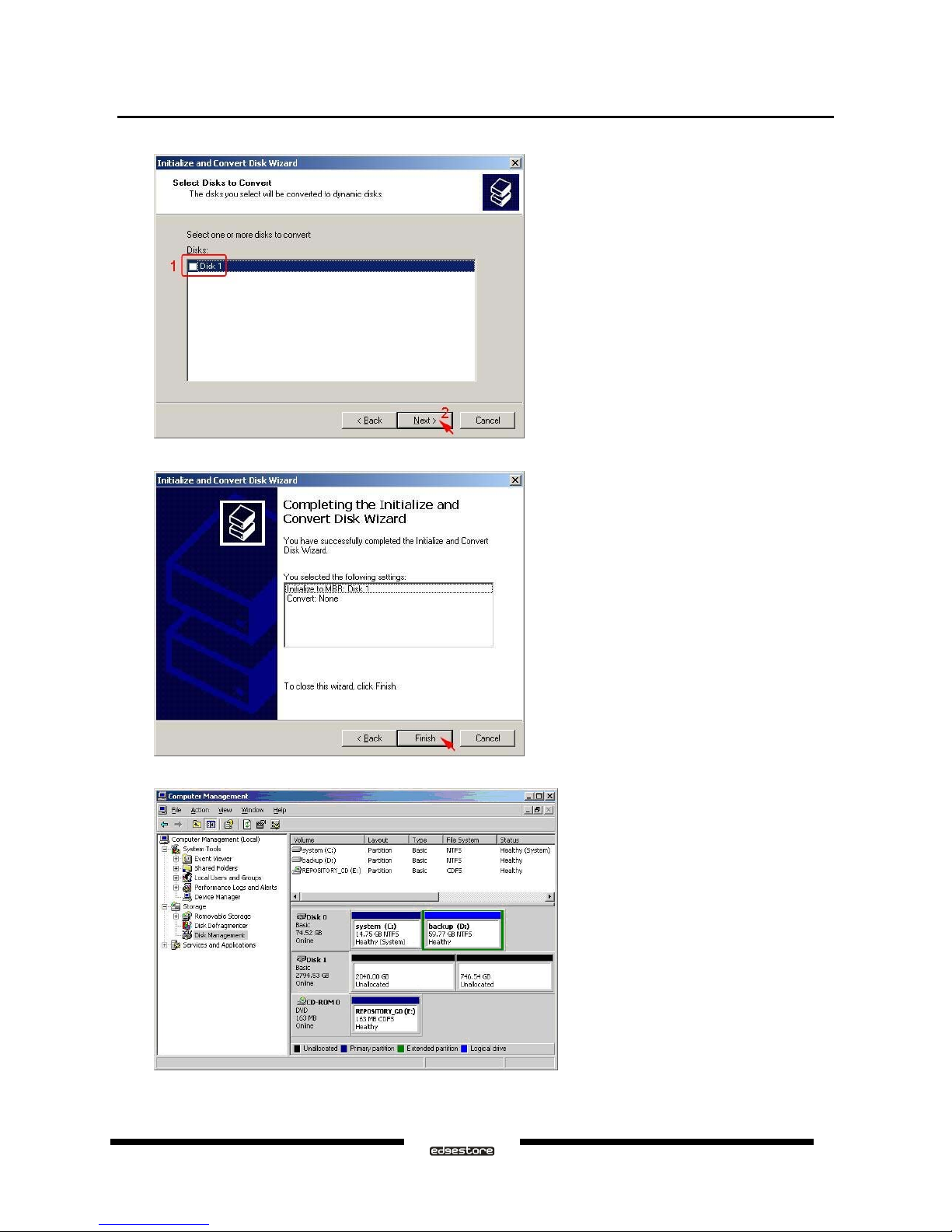
Do not click any disk to convert, than click Next.
a
When the Initialize and Convert Disk Wizard has completed, click Finish.
a
Windows Server 2003 SP1 or later system supports GPT disk which supports disk volume greater than 2TB.
DAS401 User’s Manual
Ver.071015
49
Page 50
a
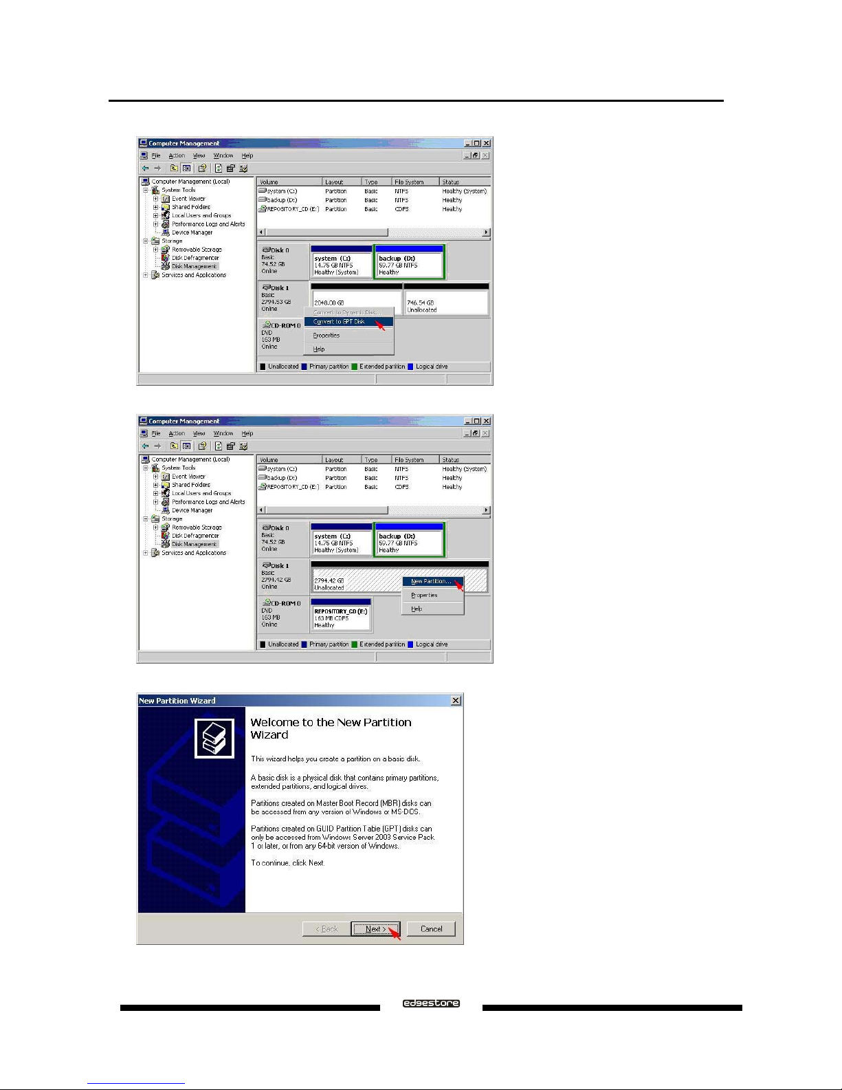
Right-click on the Basic disk and select Convert to GPT disk from the pop-up menu.
a
Right-click on the Unallocated partition and select New Partition… from the pop-up menu.
a
Click Next to create a partition on a basic disk.
Ver.071015
DAS401 User’s Manual
50
Page 51
a
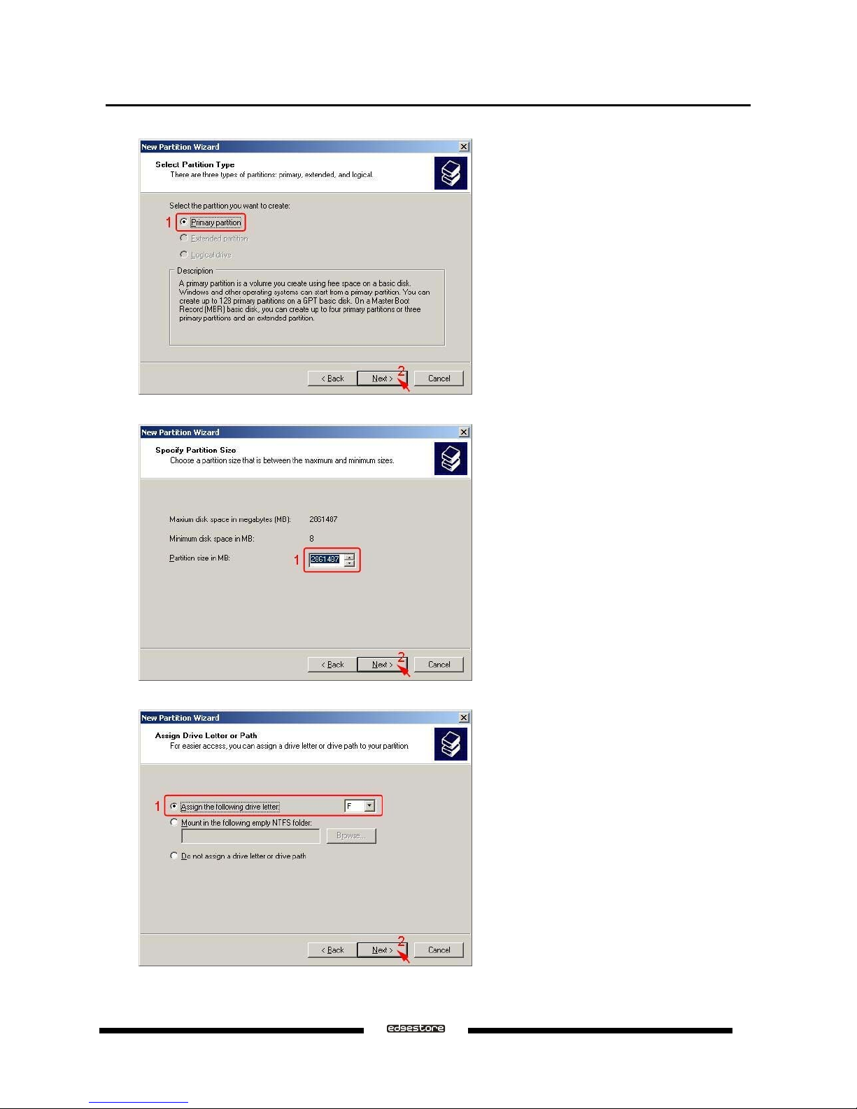
Select the partition to create, than click Next.
a
Specify the partition size you want to create, than click Next.
a
Assign the drive letter or path you want to create, than click Next.
DAS401 User’s Manual
Ver.071015
51
Page 52
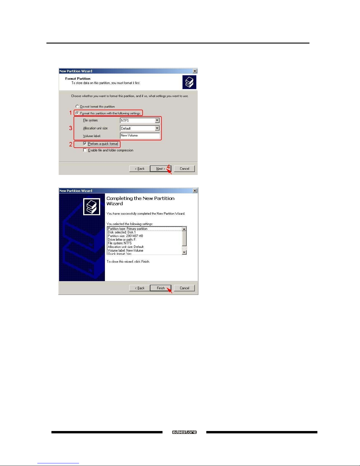
a
Click Format this partition with the following settings and Perform a quick format, setup the File
system, Allocation unit size, Volume label, than click Next.
a
When the New Partition Wizard has completed, click Finish.
Ver.071015
DAS401 User’s Manual
52
Page 53
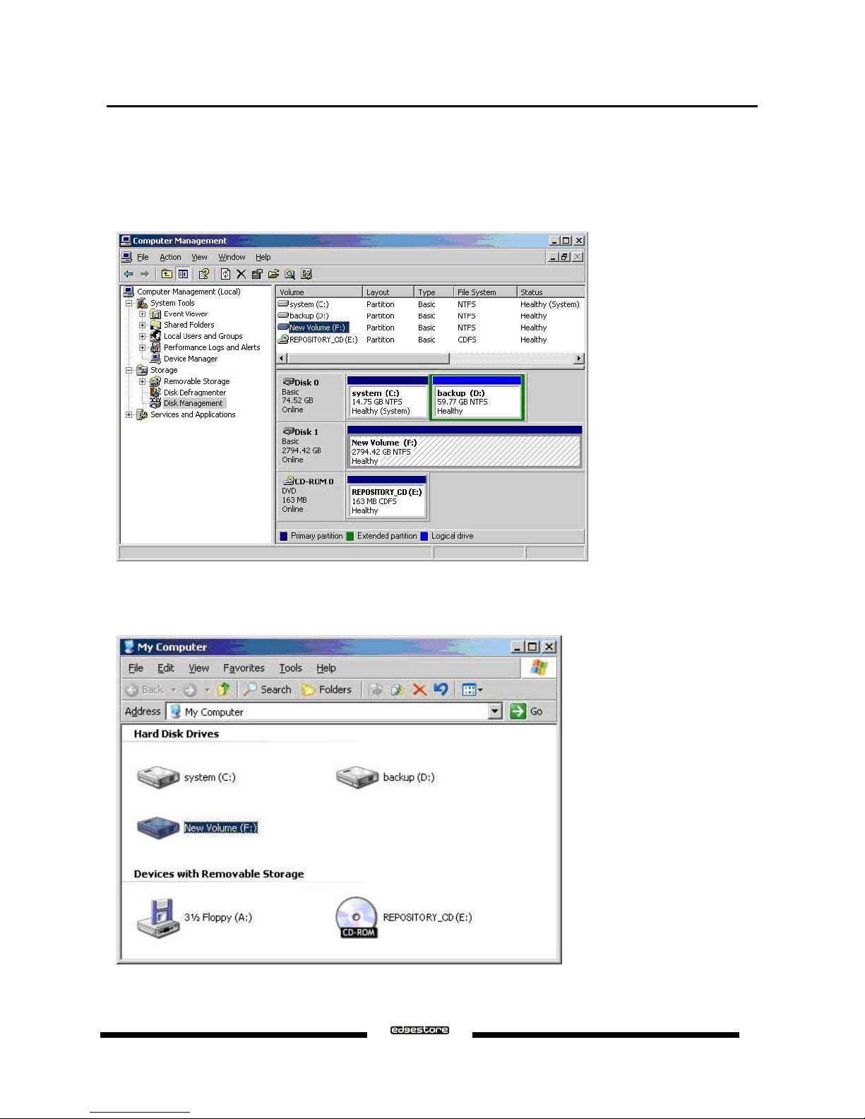
The status of the newly created partition in the Disk Management window should change to Formatting and the
percentage complete will be displayed. Depending upon the size of the partition, the format process may take
several minutes. When complete, the status will change to “Healthy" and the name and drive letter will be
updated. Once the disk reports Healthy, it appears in the listing in System Listing section with all of its pertinent
information as well.
Repeat the above procedure as needed for any other partitions. Close the Data Management window by
clicking on the small boxed “X” in the top right corner of the window. Click on the “My Computer” icon on the
Desktop. The new drives will be visible and properly named. The new disks are available for use.
DAS401 User’s Manual
Ver.071015
53
Page 54
3.6 INSTALLING ON WINDOWS VISTA
3.6.1 INSTALLING SATA RAID HOST BUS ADAPTER
Follow the descriptions below, and step by step to complete the setup.
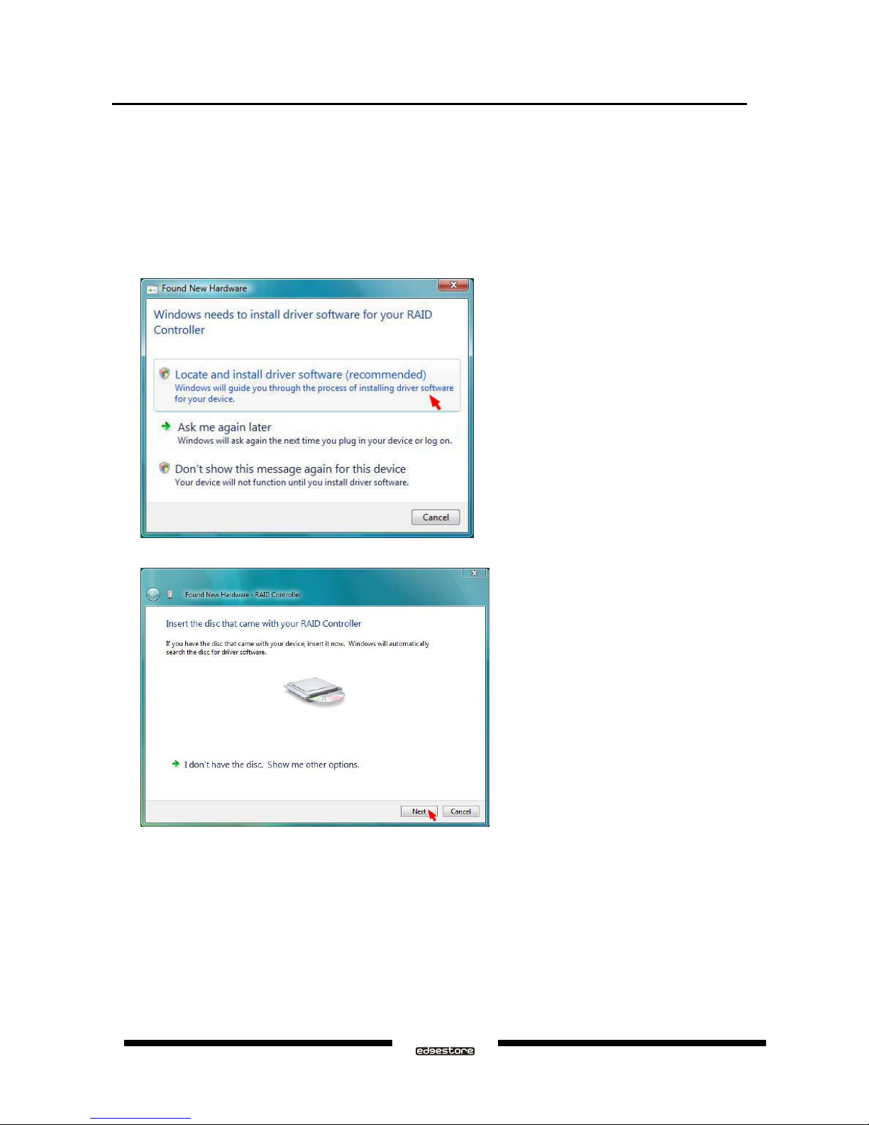
a
Insert the Setup and Installation Driver Repository CD in the CD-ROM drive.
a
When start the Windows O/S, new hardware will be found; Select Locat and install driver software
(recommended).
a
Insert the disc that came with your RAID Controller, than click Next.
Ver.071015
DAS401 User’s Manual
54
Page 55
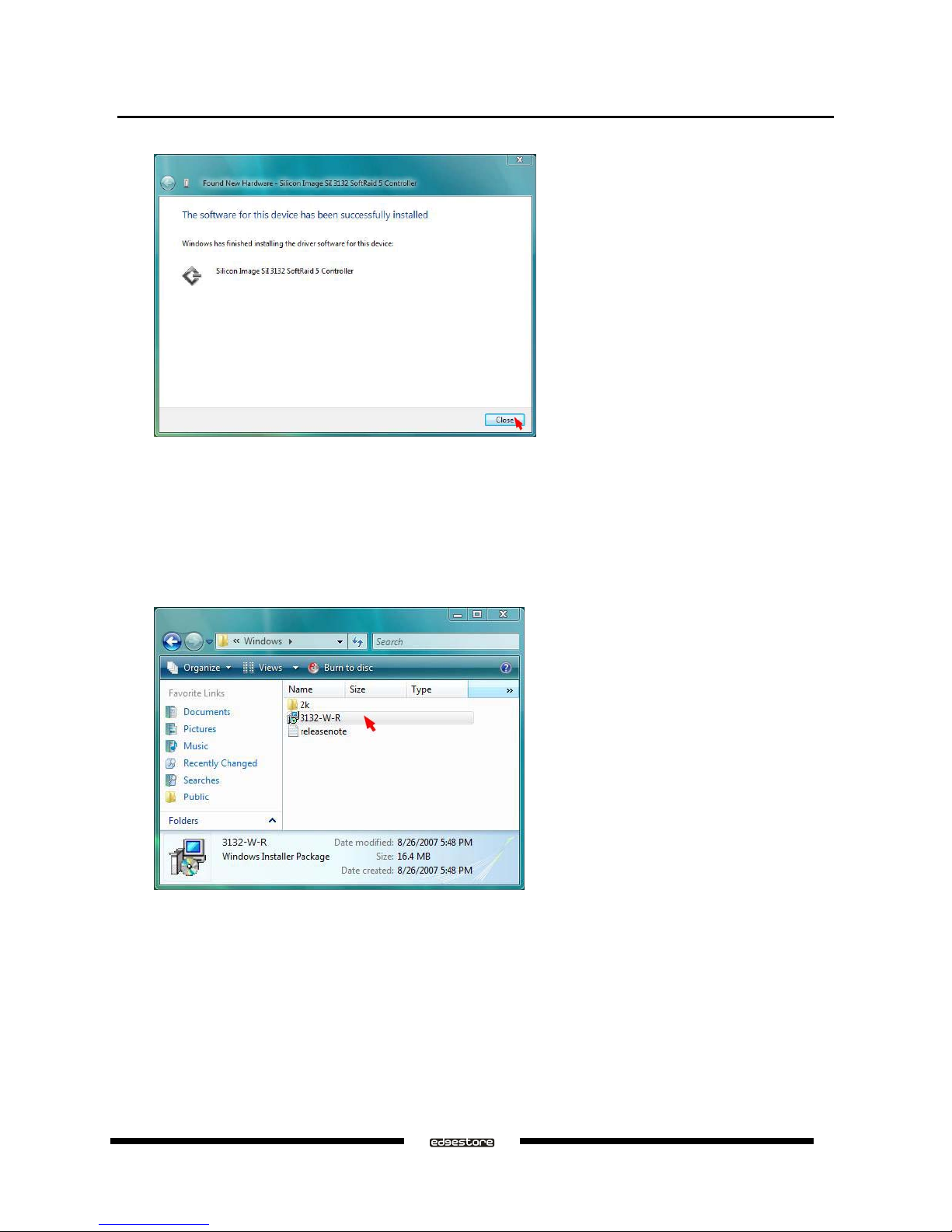
a
When the installation has completed, click Close.
3.6.2 INSTALLING SATARAID5 UTILITY
Follow the descriptions below, and step by step to complete the installation.
a
Open the Setup and Installation Driver Repository CD and select the SATARAID5 Array Manager software
from the Utility folder.
a
Double-click the 3132-W-R.msi file (Located at: E:\Utility\SiI3132R5\Windows\3132-W-R.msi; PS: "E:" =
CD-ROM drive letter).
DAS401 User’s Manual
Ver.071015
55
Page 56
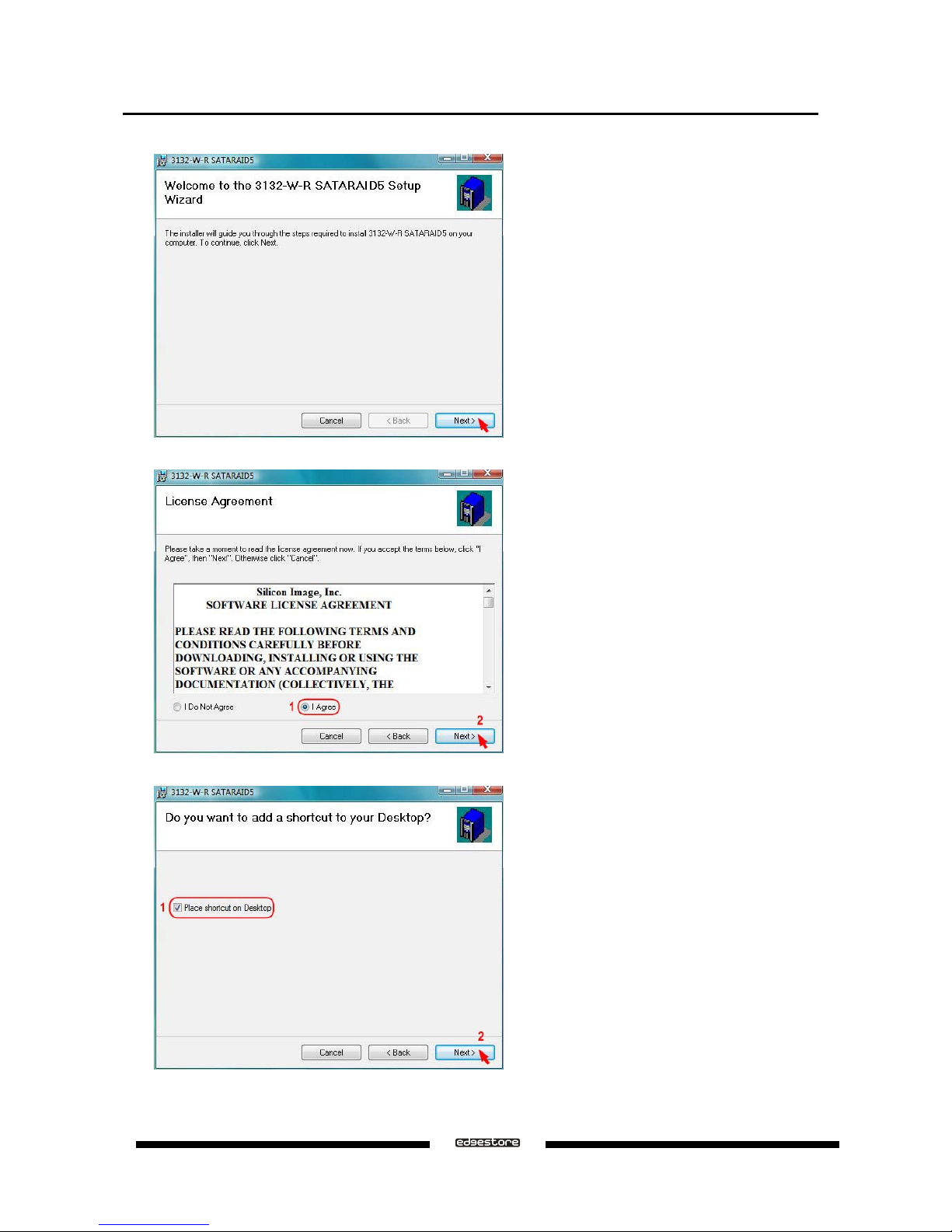
a
Click Next to begin setup.
a
Select I Agree, than click Next.
a
Select Place shortcut on Desktop, than click Next to create a shortcut on the desktop.
Ver.071015
DAS401 User’s Manual
56
Page 57
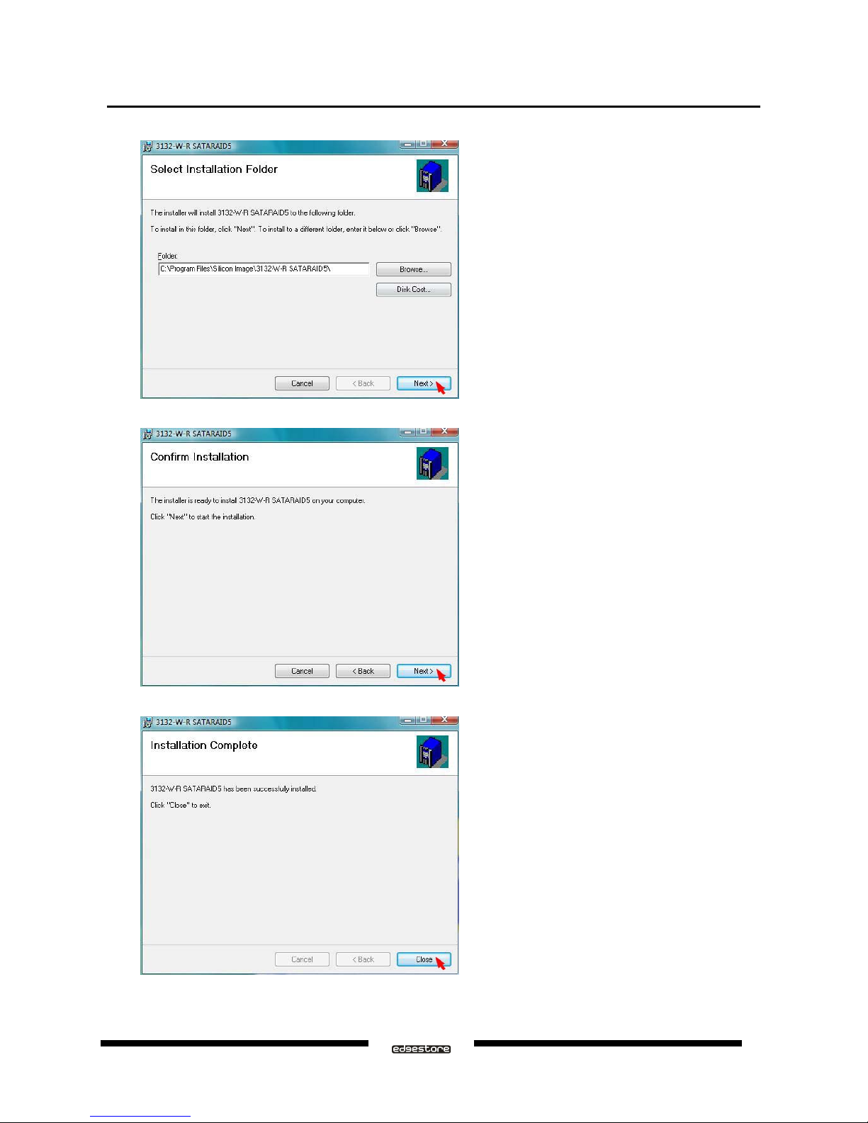
a
Click Next to use the default installation folder.
a
Click Next to begin the installation.
a
When the SATARAID5 Utility installation has completed, click Close, and begin to the Java installation.
DAS401 User’s Manual
Ver.071015
57
Page 58
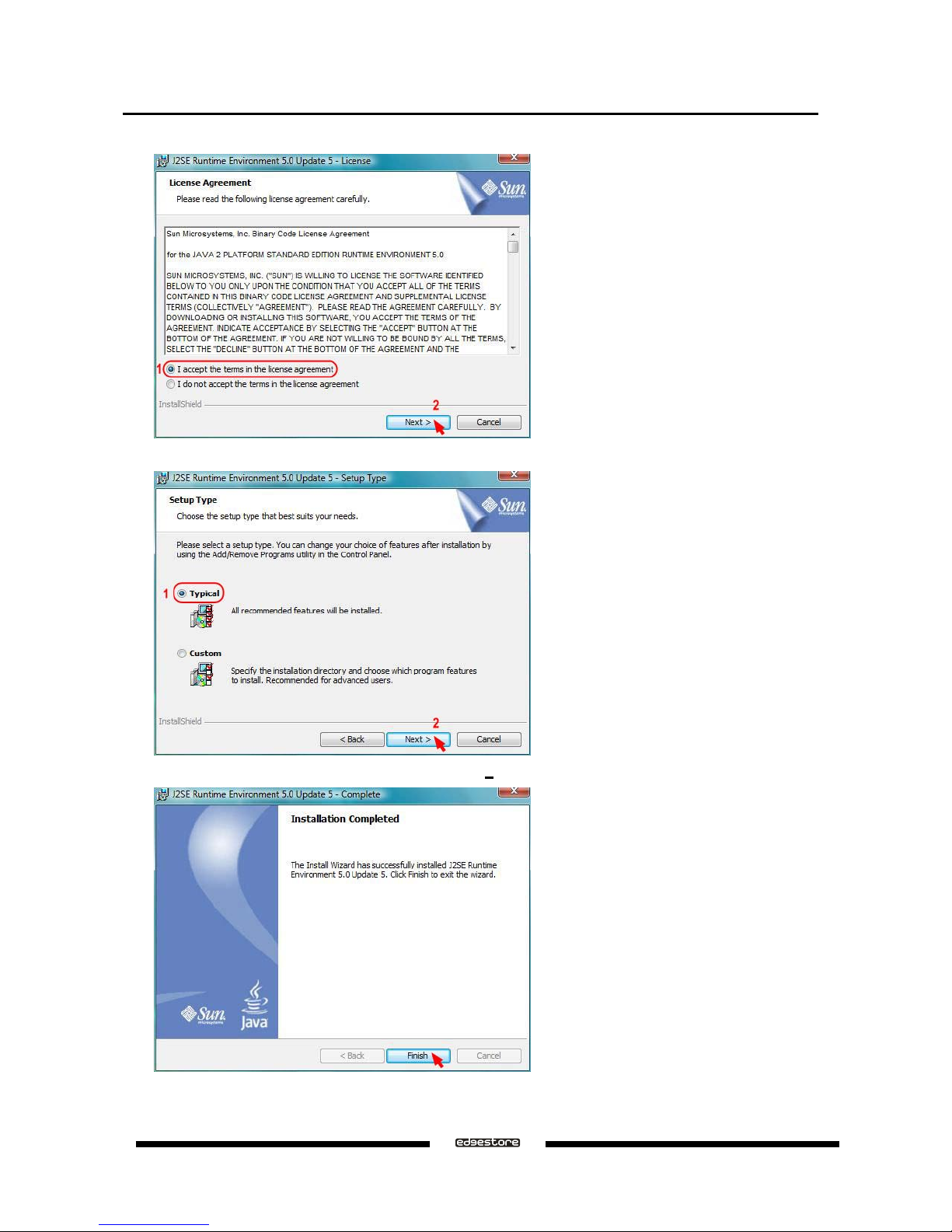
a
Select I accept the terms in the license agreement, than click Next.
a
Select Typical, than click Next.
a
When Java platform installation has completed, click Finish to exit.
a
Select Start > All Programs > Silicon Image > SATARaid5Manager to start the Array Manager software.
Ver.071015
DAS401 User’s Manual
58
Page 59
3.6.3 DISK DRIVE MODE SETUP
Please refer to the chapter 4.
3.6.4 ALLOCATING PARTITIONS
Before creating any partitions, RAID groups must first be created using the SATARaid5Manager utility. Once the
sets have been created, allow the system to load Windows.
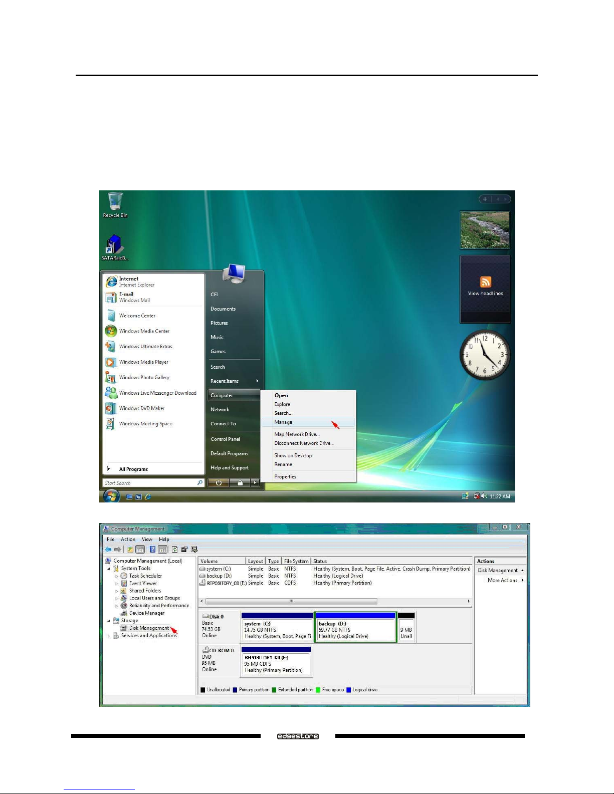
a
Right-click on My Computer icon and select Manage from the pop-up menu.
a
Select Disk Management under Storage to view the disk drives.
DAS401 User’s Manual
Ver.071015
59
Page 60
a
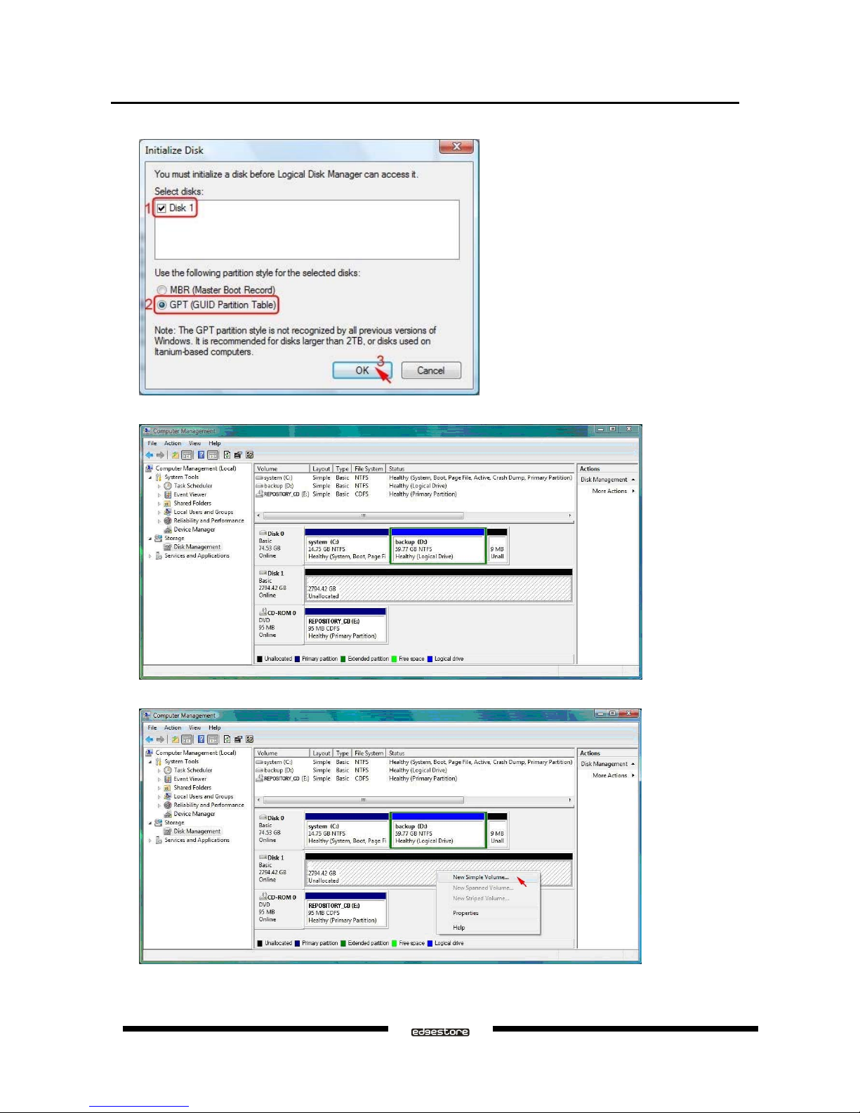
When Initialize Disk Wizard appears, select Disk 1 and GPT (GUID Partition Table), than click OK.
a
Windows Vista system supports GPT disk which supports disk volume greater than 2TB.
a
Right-click on the Unallocated partition and select New Single Volume… from the pop-up menu.
Ver.071015
DAS401 User’s Manual
60
Page 61
a
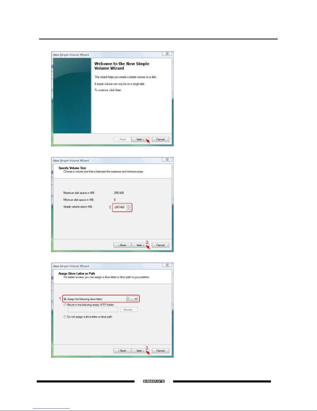
Click Next to create the partition.
a
Specify the partition size you want to create, than click Next.
a
Assign the drive letter or path you want to create, than click Next.
DAS401 User’s Manual
Ver.071015
61
Page 62
a
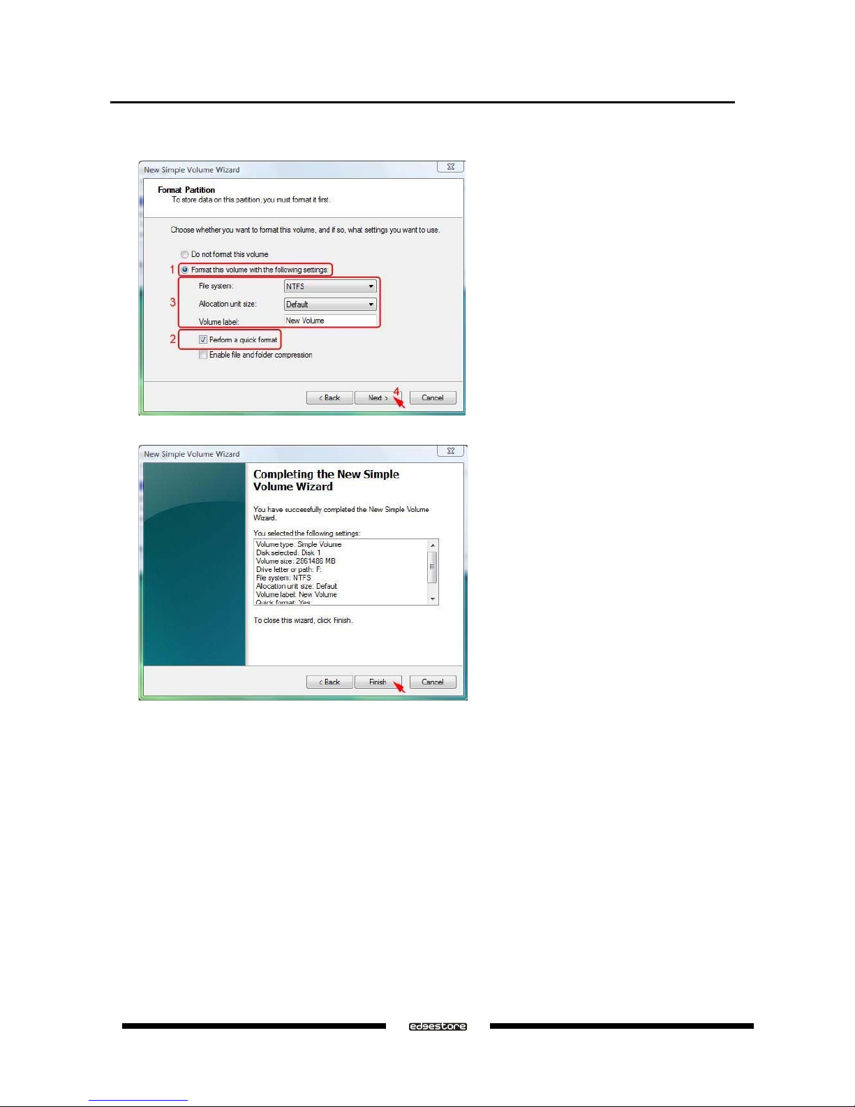
Click Format this partition with the following settings and Perform a quick format, setup the File
system, Allocation unit size, Volume label, than click Next.
a
When the New Partition Wizard has completed, click Finish.
Ver.071015
DAS401 User’s Manual
62
Page 63
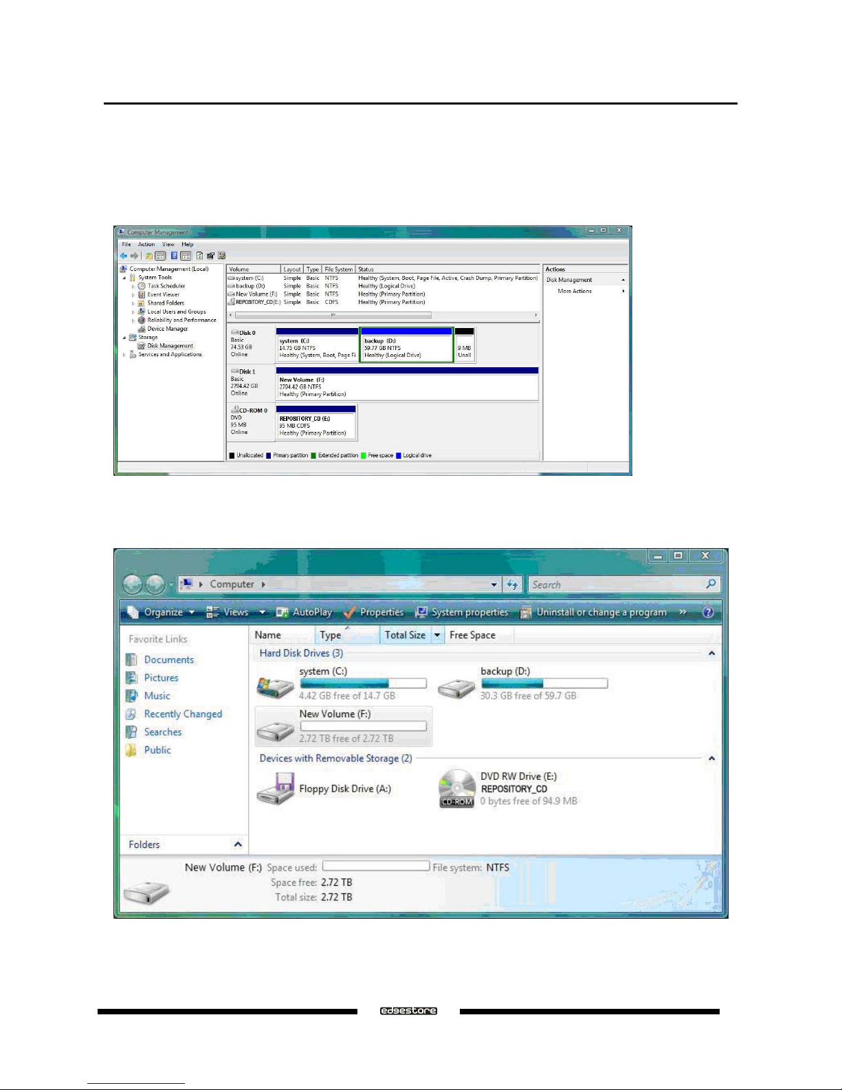
The status of the newly created partition in the Disk Management window should change to Formatting and the
percentage complete will be displayed. Depending upon the size of the partition, the format process may take
several minutes. When complete, the status will change to “Healthy" and the name and drive letter will be
updated. Once the disk reports Healthy, it appears in the listing in System Listing section with all of its pertinent
information as well.
Repeat the above procedure as needed for any other partitions. Close the Data Management window by
clicking on the small boxed “X” in the top right corner of the window. Click on the “My Computer” icon on the
Desktop. The new drives will be visible and properly named. The new disks are available for use.
DAS401 User’s Manual
Ver.071015
63
Page 64
3.7 INSTALLING ON MACINTOSH OS X
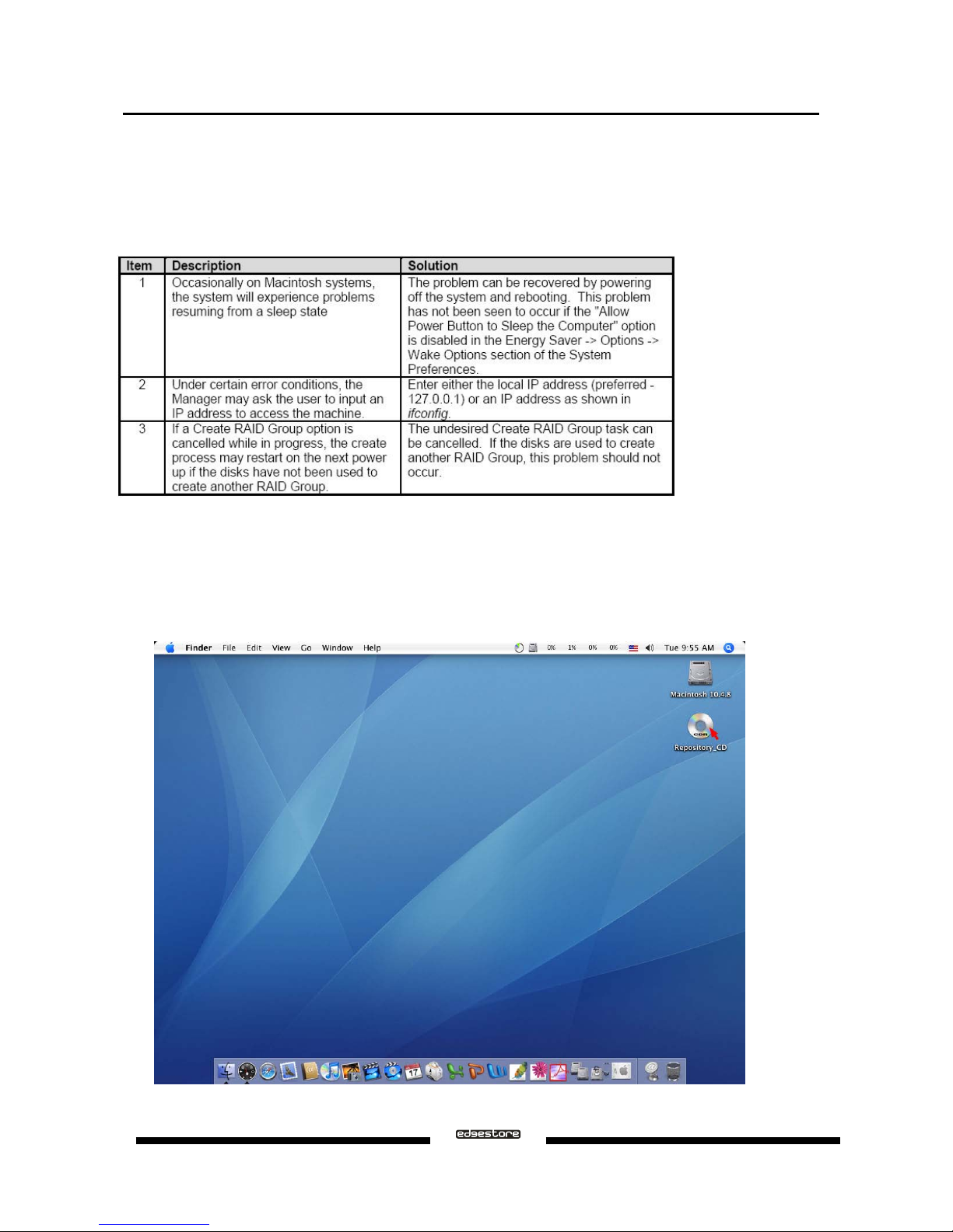
3.7.1 RELEASE NOTES
This is the premier release for the Silicon Image SATARaid5 Storage Solution for Macintosh, the follow ing issues
are known to exsit in this version.
# These issues are expected to be fixed in the next relea se.
3.7.2 INSTALLING SATA RAID HOST BUS ADAPTER AND SATARAID5 UTILITY
Follow the descriptions below, and step by step to complete the setup.
a
Insert the Setup and Installation Driver Repository CD in the CD-ROM drive.
a
When start the Mac O/S, double-click on the Setup and Installation Driver Repository CD icon.
Ver.071015
DAS401 User’s Manual
64
Page 65
a
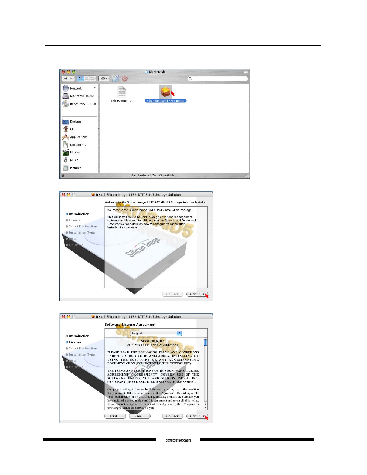
Double-click the siliconimage3132r5.mpkg file to begin the installation
(Located at: E:\Utility\SiI3132R5\Macintosh\siliconimage3132r5.mpkg; PS: "E:" = CD-ROM drive letter).
a
Once started, the following dialog screens will appear, Click Continue.
a
Read the Software License Agreement, than click Continue.
DAS401 User’s Manual
Ver.071015
65
Page 66
a
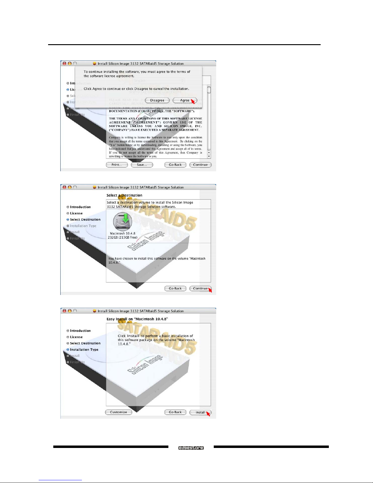
Click Agree to continue the installation.
a
Select a destination volume to install the software, than click Continue.
a
Click Install to begin the installation.
Ver.071015
DAS401 User’s Manual
66
Page 67
a
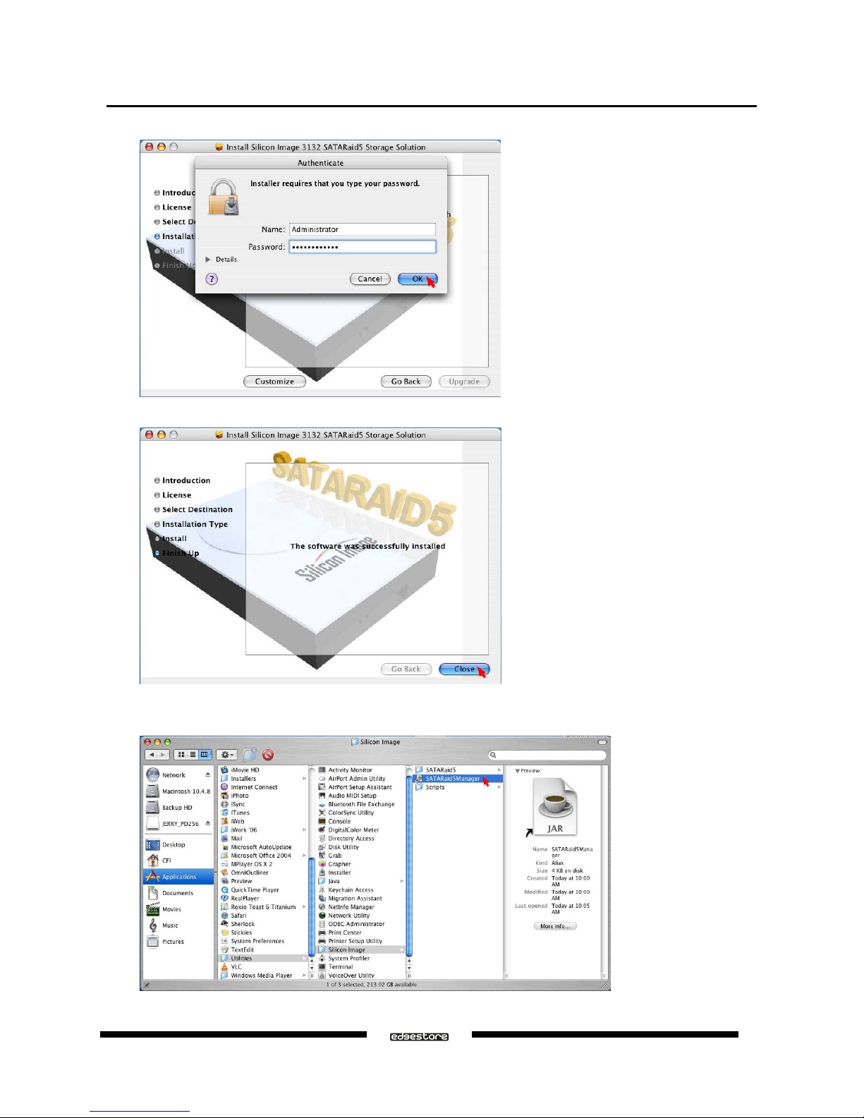
Enter the Administrative Password for your system, than click OK.
a
Click Close to complete the installation.
a
Select Go > Computer > Applications > Utilities > Silicon Image > SATARaid5Manager to start the
Array Manager software.
DAS401 User’s Manual
Ver.071015
67
Page 68
3.7.3 DISK DRIVE MODE SETUP
Please refer to the chapter 4.
3.7.4 ALLOCATING PARTITIONS
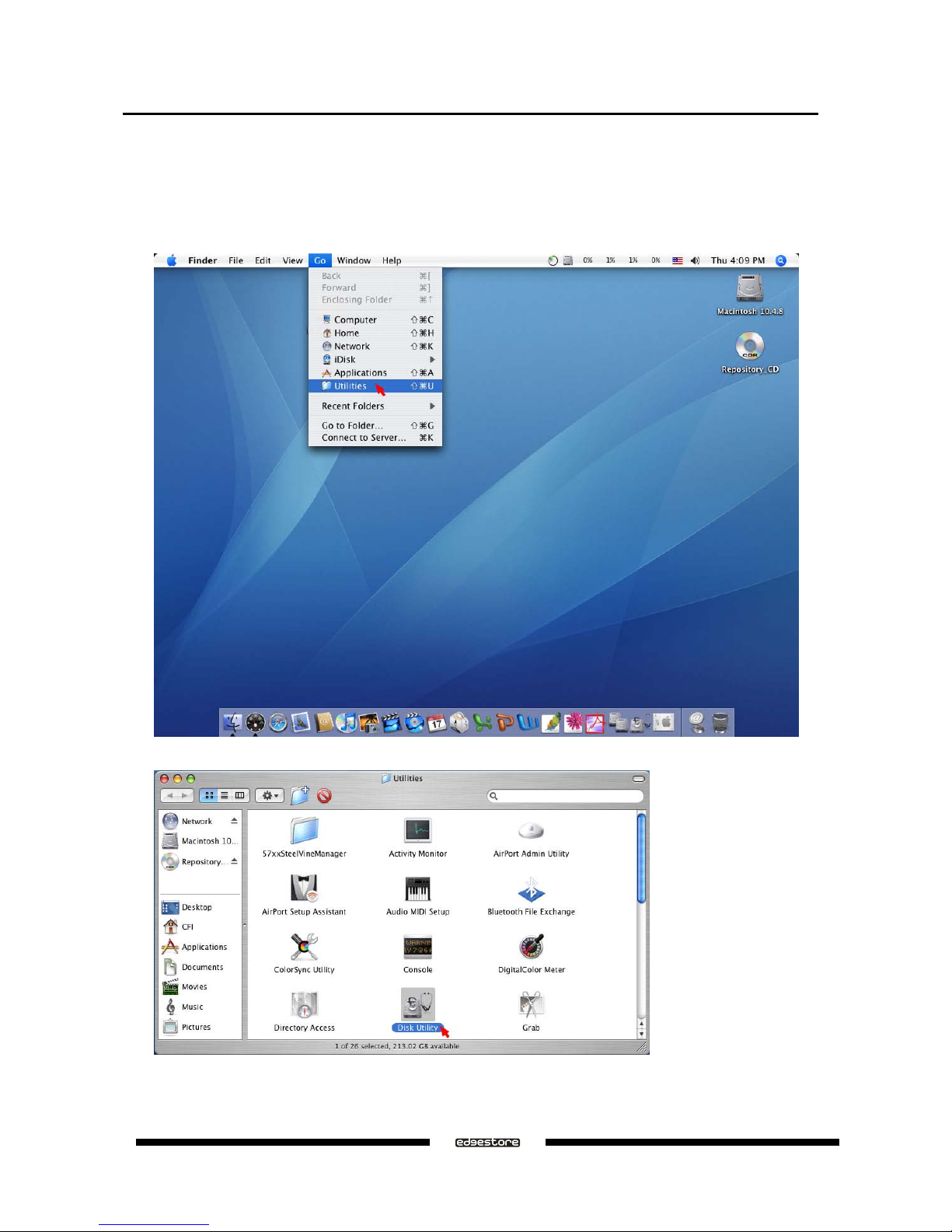
a
Click Go, than click on Utilities.
a
Double-click Disk Utility to go to Disk Utility.
Ver.071015
DAS401 User’s Manual
68
Page 69
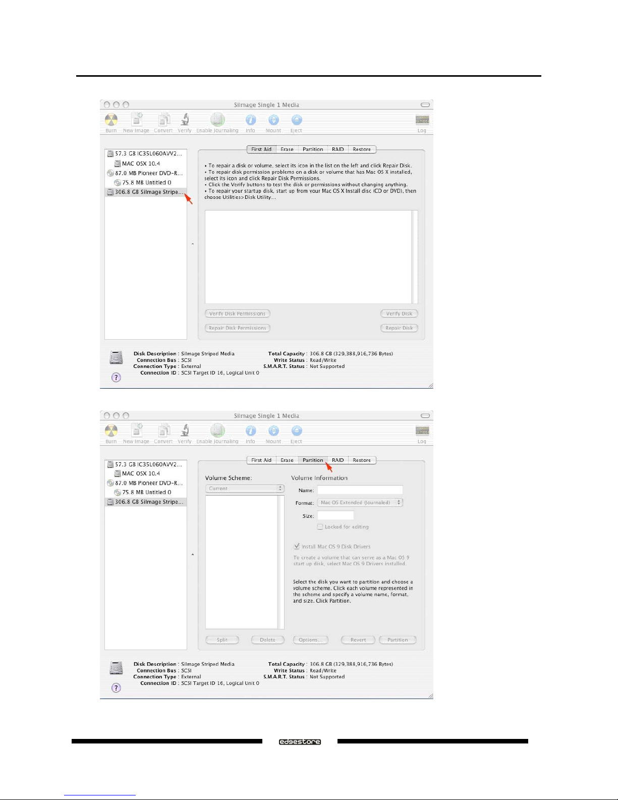
a
Select the disk you want to partition (On left side of the window).
a
Click Partition to go to partition window (On right side of the window).
DAS401 User’s Manual
Ver.071015
69
Page 70
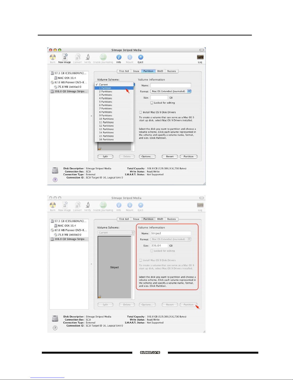
a
Select Volumes Scheme.
a
Enter Volumes Information, than click Partition.
Ver.071015
DAS401 User’s Manual
70
Page 71
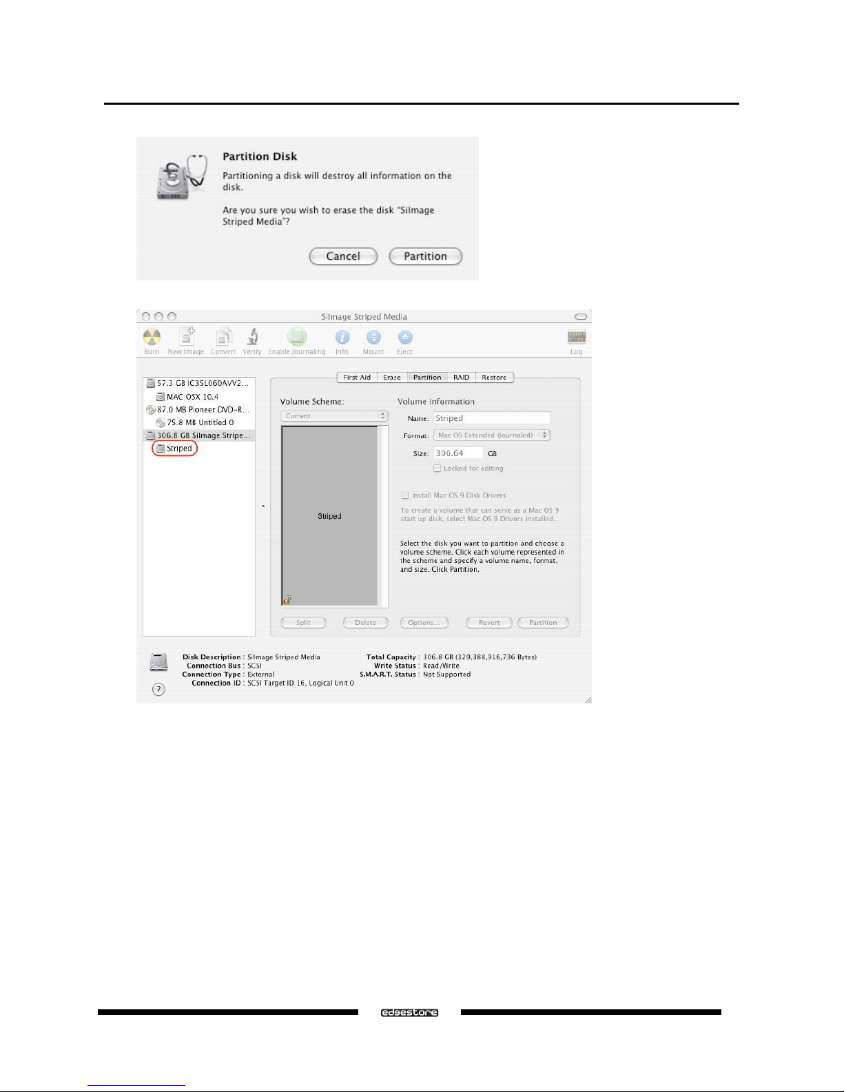
a
Confirm to partition the disk by click Partition.
a
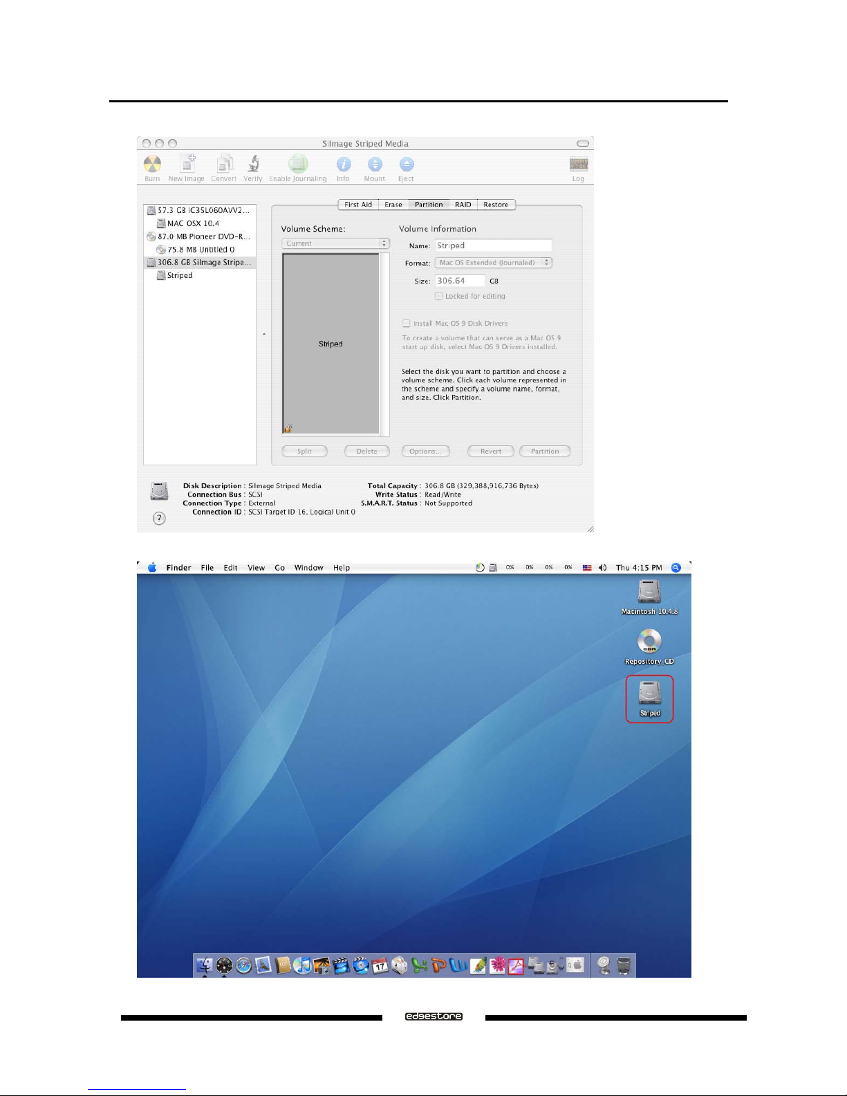
The new Striped disk has complete.
a
Repeat the above procedure as needed for any other disks.
DAS401 User’s Manual
Ver.071015
71
Page 72
a
Close the Disk Utility window after complete setting.
a
The new disks will appear on the desktop and ready for use..
Ver.071015
DAS401 User’s Manual
72
Page 73
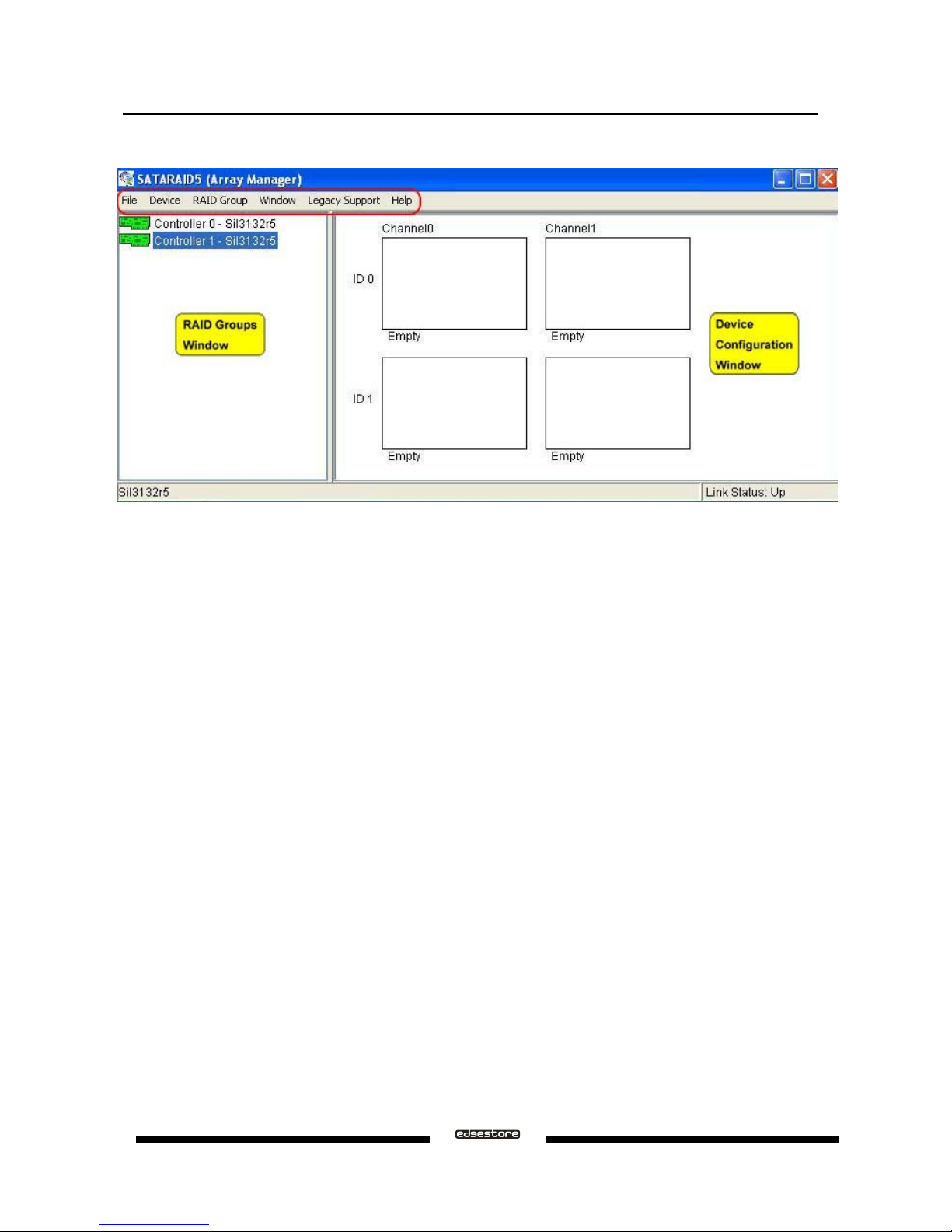
4 SATARAID5 ARRAY MANAGER
4.1 OVERVIEW
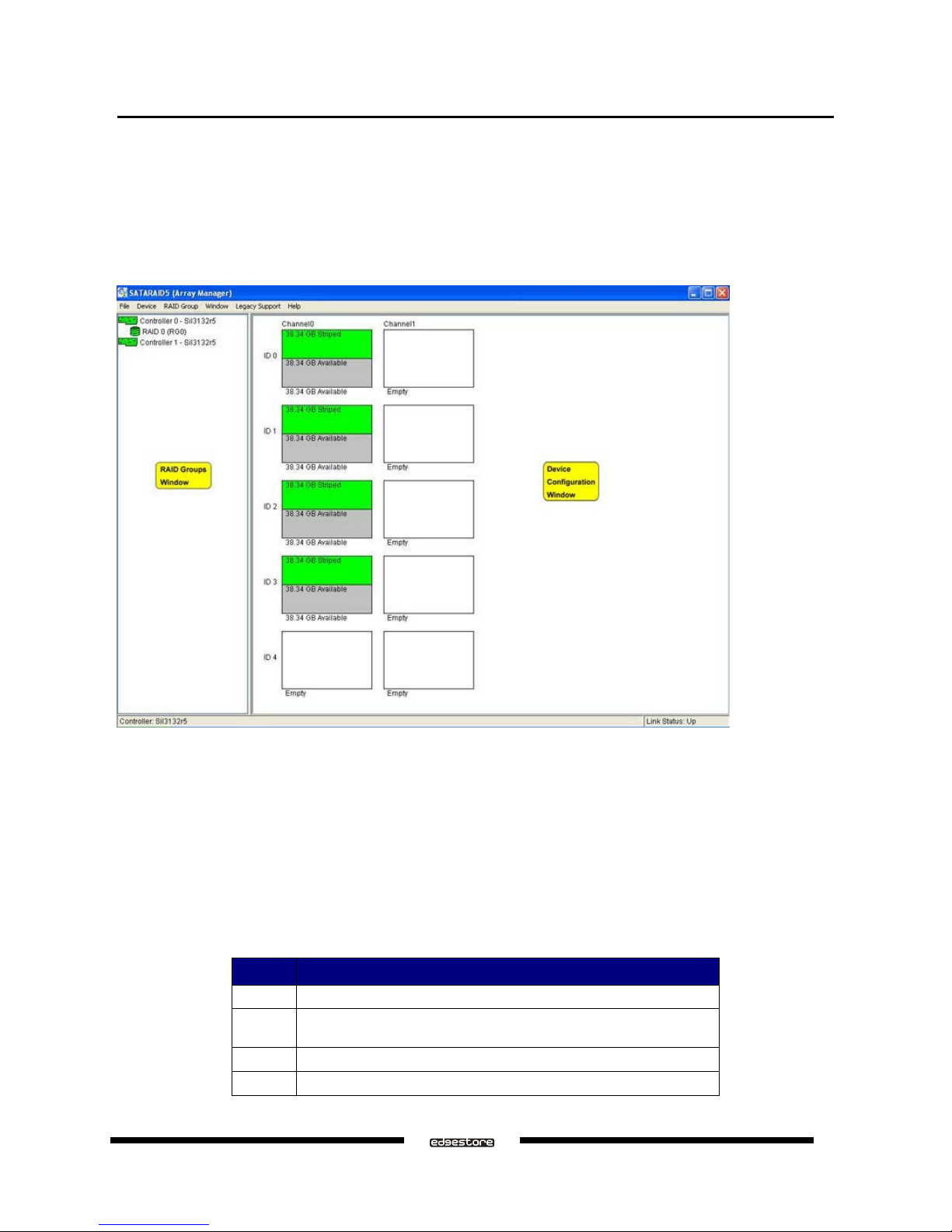
The SATARAID5 Array Manager is the Graphical User Interfaces (GUI) which allows you to create and manage
RAID volumes. The Manager initially shows two windows as seen below.
The RAID Groups window identifies SATA host adapters and configured RAID groups. For systems with more
than one Silicon Image Host Bus Adapter installed, you can switch between cards by selecting the desired card in
the RAID Groups Window.
When a controller is selected, the RAID Groups currently defined on that controller are also shown in the RAID
Groups Window. Selecting a specific RAID Group will highlight the segments associated with that volume in the
Device Configuration Window.
The Device Configuration window identifies all physical drives and their partitions.
Throughout the Manager, different colors are used to indicate the status of the components. The meanings of the
colors are:
COLOR STATUS
Green Good. The component and all subcomponents are okay.
Yellow Warning. This component or at least one subcomponent has become
degraded and requires service.
Red Failed. This component or at least one subcomponent has failed.
Grey Unused.
DAS401 User’s Manual
Ver.071015
73
Page 74
4.2 CREATING RAID GROUPS
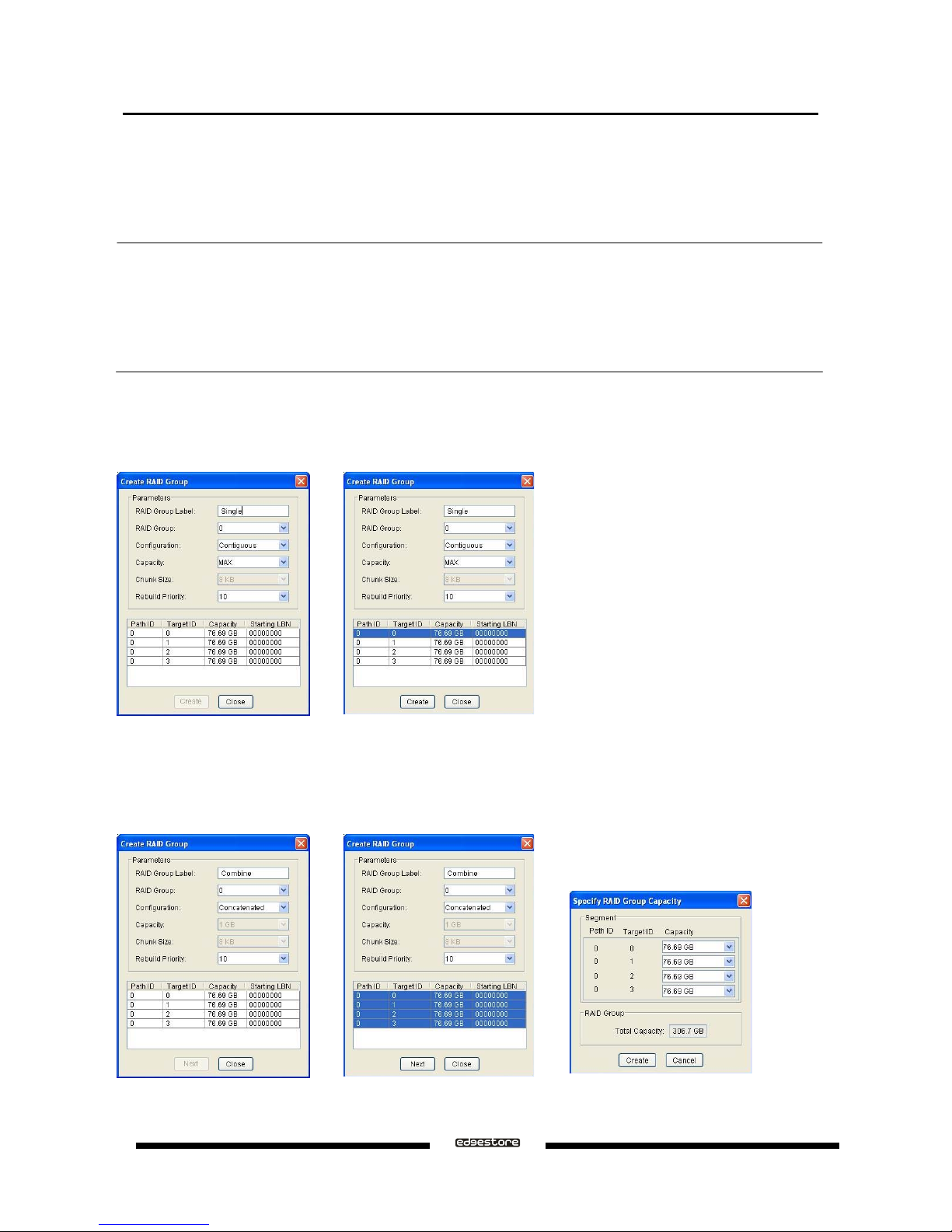
To begin creating a new RAID Group, select “Create RAID Group” from the RAID Group menu or right click on a
controller in the RAID Groups window and select “Create RAID Group” from the pop-up menu. This will cause
the Create RAID Group dialog to a ppear.
Note: The term “right-click” refers to using the secondary button on your mouse to perform the indicated
operation. On a Windows system, use the mouse button that you have defined to be the secondary
button (by default, that button is on the right side of the mouse, unless you have reconfigured the
primary and secondary mouse buttons using Control Panel > Mouse). On a Macintosh system, press
and hold the Command (Apple) key and click the mouse.
4.2.1 CONTIGUOUS RAID GROUPS
Contiguous RAID Groups allow the user to select a segment of disk drive or a disk drive. Select the disk and
enter the desired values and press Create to create the RAID Group (Example below).
4.2.2 CONCATENATED RAID GROUPS
Concatenated RAID Groups allow the user to select different sized se gme nts for each mem b er of the vol u me.
For Concatenated volumes only, a dialog box will appear allowing the user to select the individual segment sizes
from each disk. Enter the desired values and press Create to create the RAID Group (Example below).
Ver.071015
DAS401 User’s Manual
74
Page 75
4.2.3 STRIPED RAID GROUPS
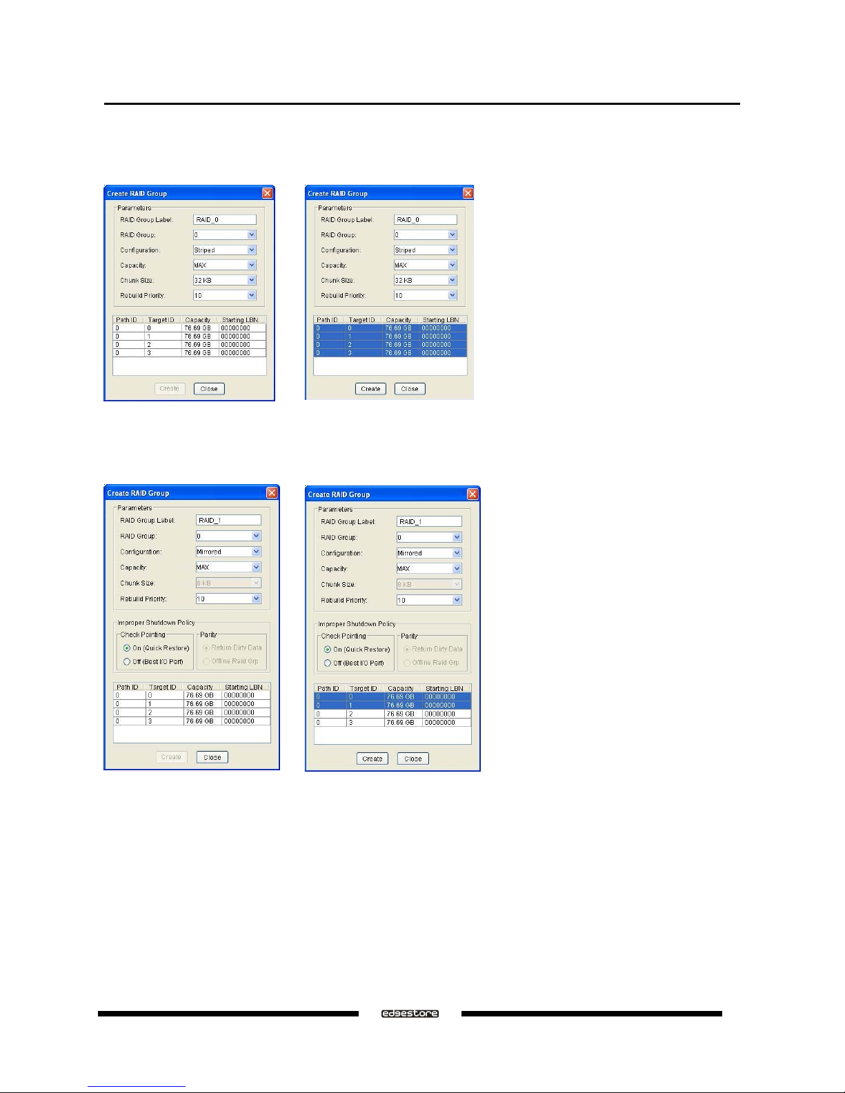
Striped RAID Groups allow the user to select minimum of 2 or more disks for each member of the volume. Enter
the desired values and press Create to create the RAID Group (Example below).
4.2.4 MIRRORED RAID GROUPS
Mirrored RAID Groups allow the user to select 2 disks for each member of the volume. Enter the desired values
and press Create to create the RAID Group (Example below).
DAS401 User’s Manual
Ver.071015
75
Page 76
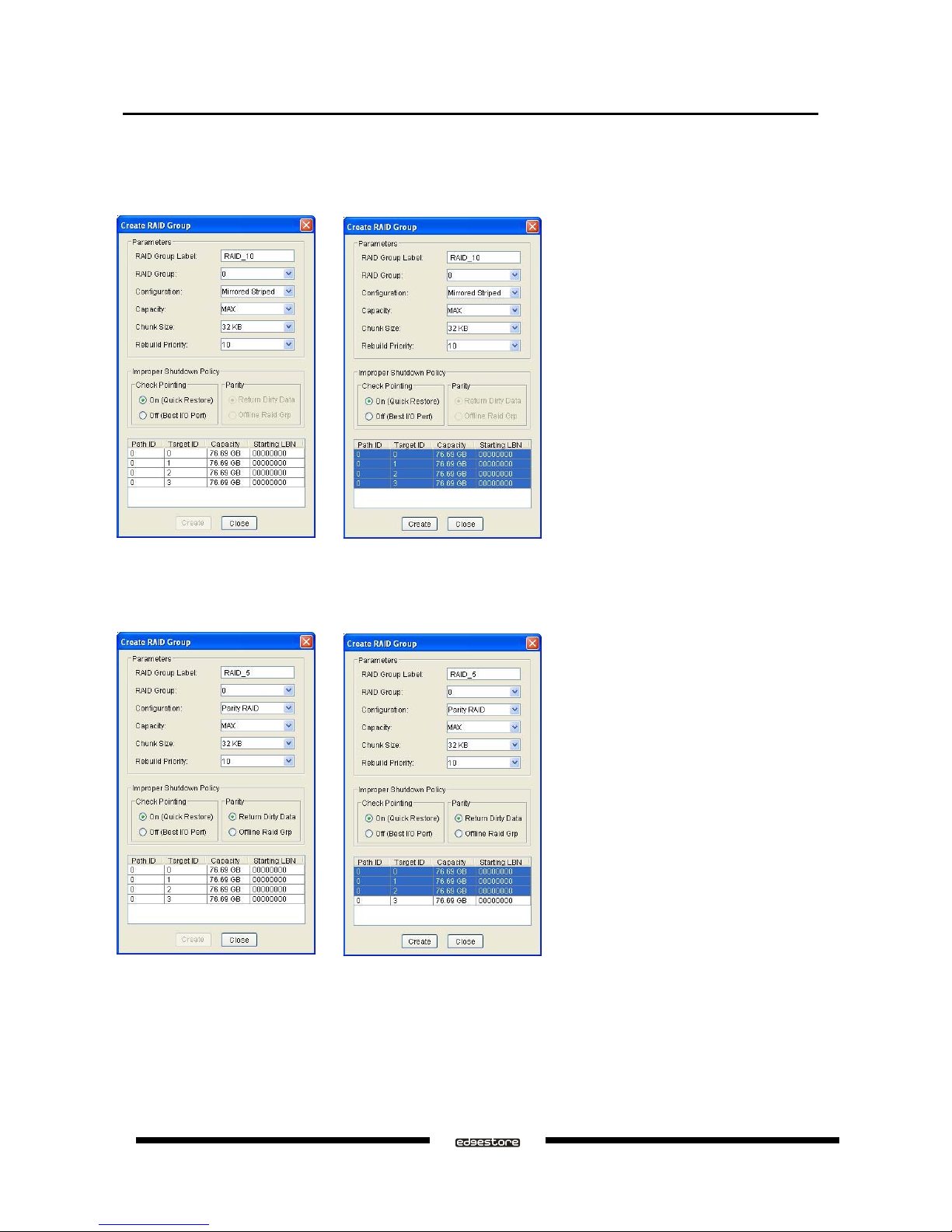
4.2.5 MIRRORED STRIPED RAID GROUPS
Mirrored Striped RAID Groups allow the user to select minimum of 4 disks for each member of the volume. Enter
the desired values and press Create to create the RAID Group (Example below).
4.2.6 PARITY RAID GROUPS
Parity RAID Groups allow the user to select minimum of 3 or more disks for each member of the volume. Enter
the desired values and press Create to create the RAID Group (Example below).
Ver.071015
DAS401 User’s Manual
76
Page 77
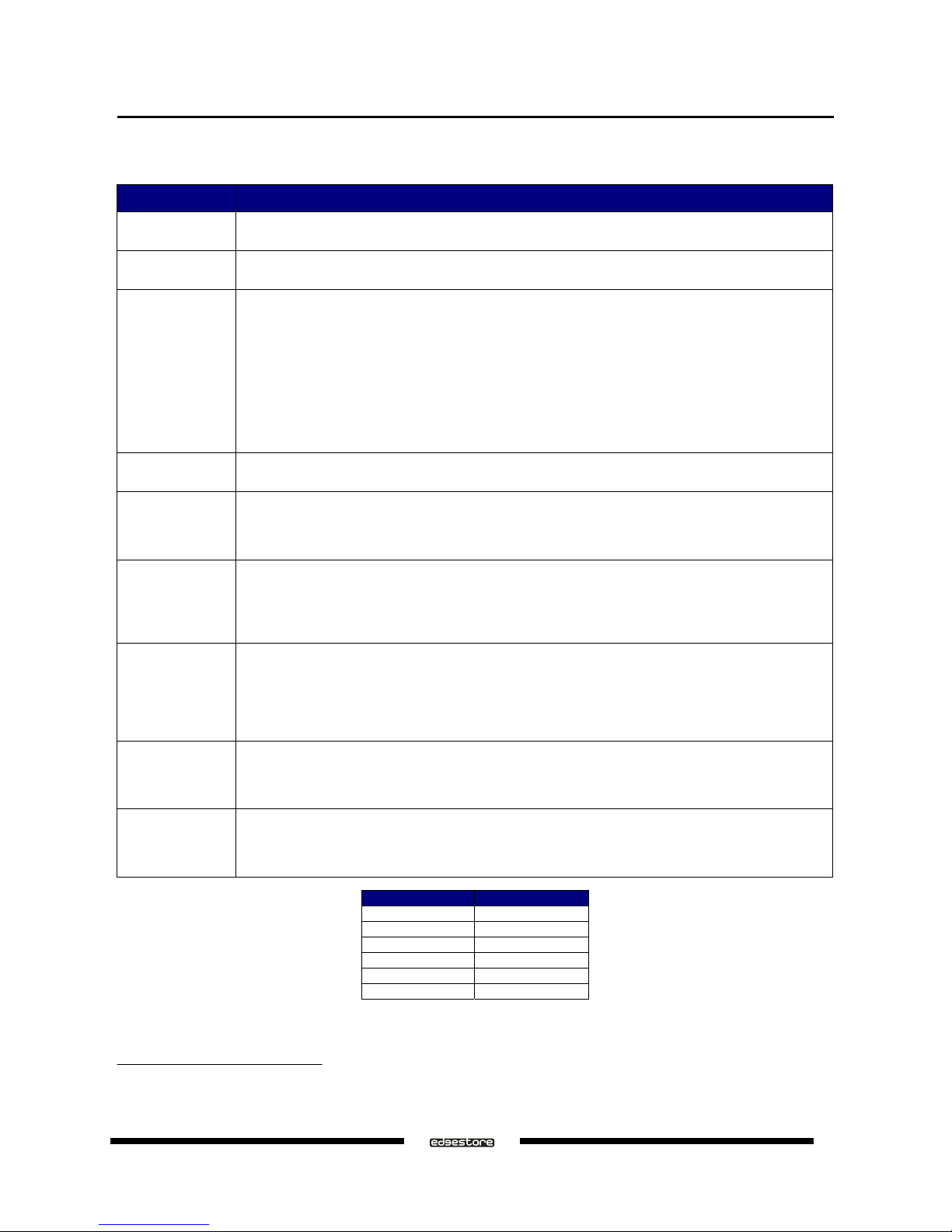
4.2.7 RAID GROUPS OVERVIEW
RAID Groups allow Enter values in all fields and click Create to create the RAID Group.
FIELD
DEFINITION
RAID Group
Label
Enter an identifiable name for the RAID group. This value can be any string (up to 8 characters
including blank spaces) to help users identify this volume.
RAID Group
Select a Group ID from the available ID list. The maximum number of RAID Groups per controller is 8,
so Group ID can be any number between 0 and 7, inclusive.
Configuration
Select which RAID level is to be used to configure these members:
• Contiguous (for virtual disk).
• Concatenated (for multiple concatenated segments).
• Striped (for RAID 0)
• Mirrored (for RAID 1)
• Mirrored Striped (for RAID 10)
• Parity RAID (for RAID 5)
Capacity
Select a value to define the total usable capacity of the RAID Group or manually enter the volume size
in gigabytes (GB). Selecting MAX will create the largest RAID set possible with the drive(s) selected.
Chunk Size
Select a value to define the chunk size (stripe size) for performance tuning. In general, large stripe
sizes are best for large files that are accessed sequentially (for example, media streaming files) and
smaller sizes are better for randomly accessed data like databases. This parameter is not used for
Contiguous (JBOD), Concatenated, and Mirrored configurations.
Rebuild Priority
Select a value to identify how quickly the controller should rebuild data on a disk after a hardware
failure. A value of 1 is the lowest priority and will take the longest to rebuild. A value of 10 is the highest
priority and will rebuild the fastest, but may require more CPU resources, which might affect the
computer’s performance. This parameter is not used for Contiguous (JBOD), Concatenated, and
Striped configurations.
Check Pointing
Click the On or Off button to enable or disable the Check Pointing feature. When Check Pointing is
enabled, restoring data is very fast after an unexpected power loss, although normal performance may
be slightly reduced. When Check Pointing is disabled, normal performance is improved, but restores
can take a long time to complete. This selection is only available when the selected RAID configuration
is Mirrored, Mirrored Striped or Pari ty RAID, and the “Advan ced RAID Features” checkbox in the
Configuration/Advanced Options dialog is checked.
Parity
Click the On or Off button to enable or disable the ability to return “dirty” data after an unexpected
power loss and all of the data could not be written to disk, rather than taking the volume off-line. This
selection is only available when the selected RAID configuration is Parity RAID and the “Advanced
RAID Features” checkbox in the Configuration/Advanced Options dialog is checked.
Devices
Select the RAID member devices from the available device segment grid. Up to five members can be
selected for Contiguous, Concatenated, Mirrored, Striped or Parity RAID modes (although Mirrored
RAID Groups will typically contain only two members). Exactly four members must be selected for
Mirrored Striped mode.
RAID Level Min # ofDisks
0 2
1 2
5
3
*
10
4
*
Contiguous 1
Concatenated 1
Once all parameters have been selected, select “Create” to create the RAID Group. When finished, press Cancel
to exit the Create RAID Group Dialog.
*
For 3132, this requires the use of a Port Multiplier device to access more than one disk per SATA channel.
DAS401 User’s Manual
Ver.071015
77
Page 78
4.3 ADDITIONAL MENU COMMANDS
The Main menu commands are shown below
File Device RAID Group Window Legacy Support Help
Configuration… Create Spare
Create RAID Group
Task Manager Create Legacy RAID Group
Help Topics
Exit
Delete Spare
Rebuild RAID Group
Event Log
Rebuild Legacy RAID Group
About
Delete Member
Delete RAID Group
Resources
Delete Legacy RAID Group
Delete Orphan
Bring RAID Group
Online
Convert Legacy RAID Group
Make Pass-Thru RAID Group Summary
Bring Legacy RAID Group Online
Device Summary
Create Legacy Spare
Delete Legacy Spare
Convert Legacy Spare
The commands are documented on the pages that follow.
Ver.071015
DAS401 User’s Manual
78
Page 79
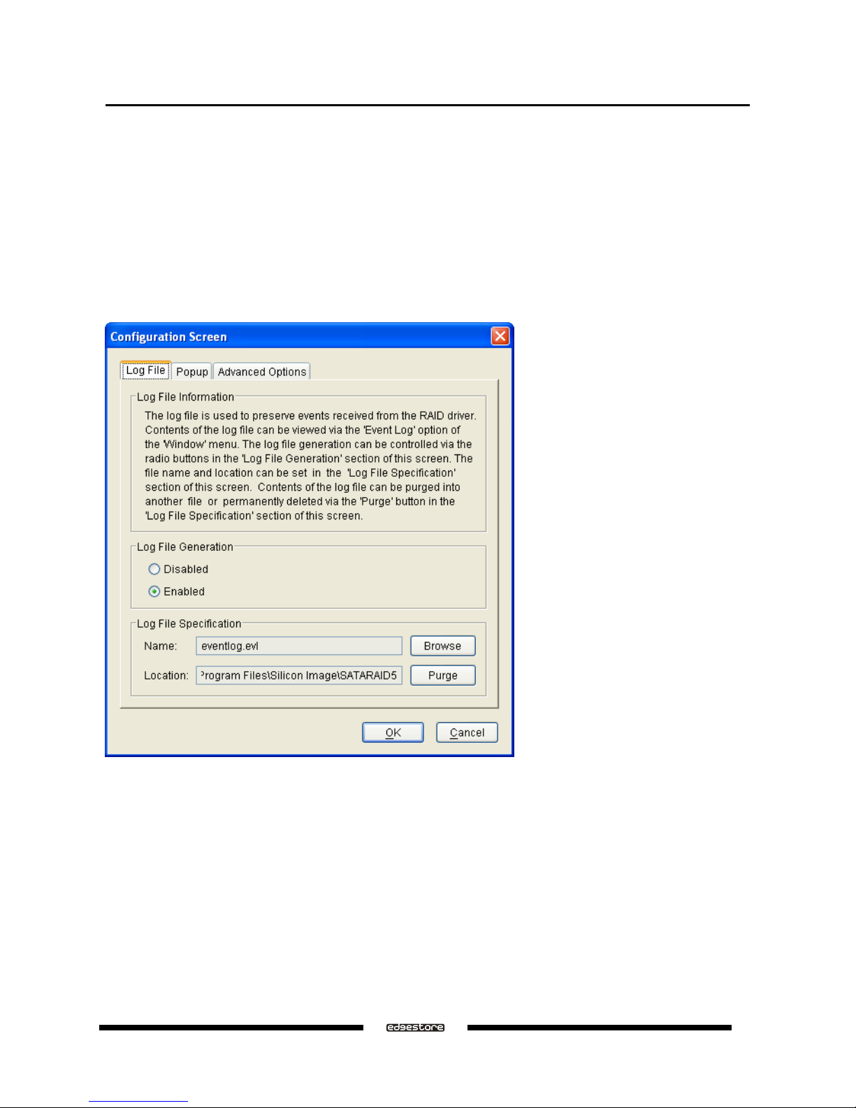
4.3.1 CONFIGURATION
SATARAID5 configuration options include customization of the settings for Log File, Popup, and Advanced
Options. This command displays a dialog box to let user set differe nt configurations for SATARAID5 with
the following three tabs:
Log File Tab
The Log File tab allows you to define the location and name of the log file. The log file is used to store event
information received from all Silicon Image RAID drivers. The log file is a text file and can be viewed with any text
viewer (such as “Notepad” on Windows platforms) or with the Event Log window of the SATARAID5 Manager.
Use the Log File tab to set the location and the desired filename for the log file.
To specify whether the Log File is generated, click on either the Disabled or Enabled radio button. If Log File
generation is enabled, you can click the Browse button to specify the file name and location of the Log File. You
can also use the Purge button to delete the conten ts of the Log Fil e .
DAS401 User’s Manual
Ver.071015
79
Page 80
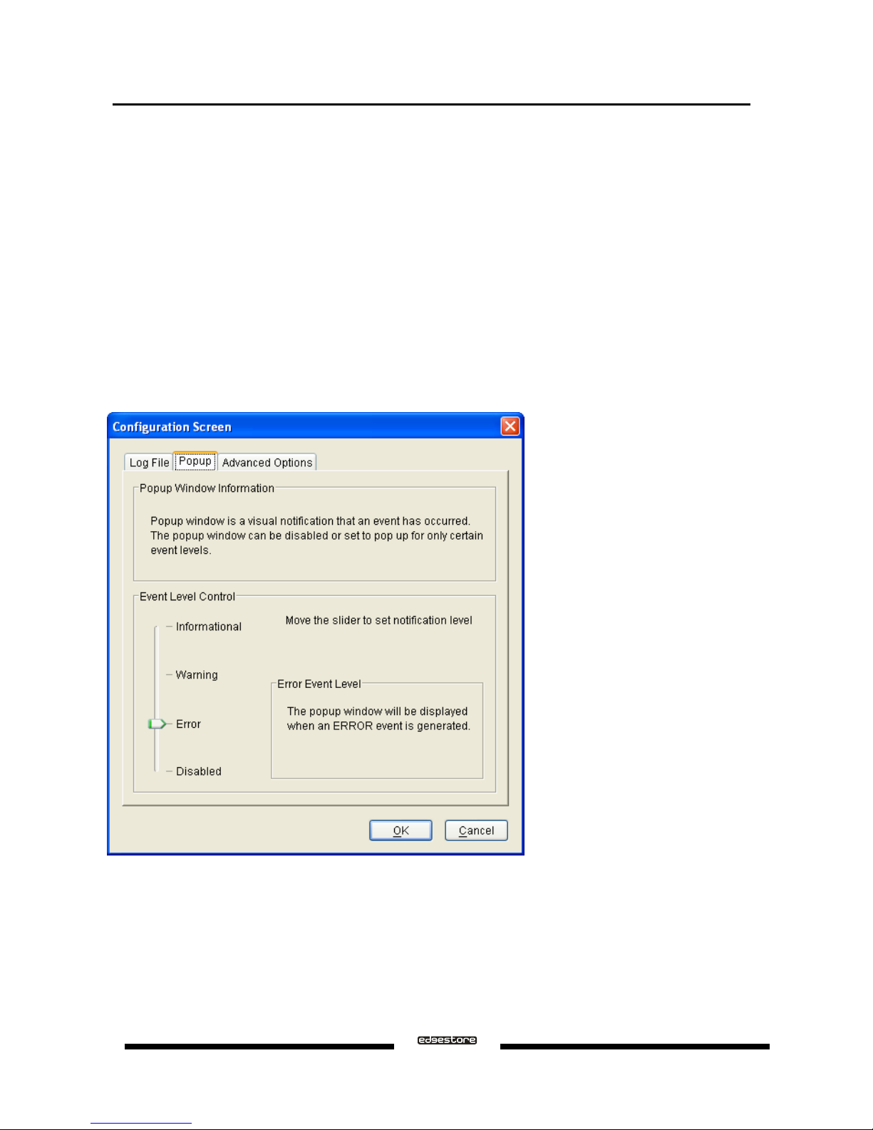
Popup Tab
SATARAID5 can be configured to notify the user of events using messages in popup windows. Use the slider
control to set the event level for popups to occur:
- Information Leve l - The following events will trigger a popup window:
e
Informational
e
Warnings
e
Errors
- Warning Level - The following events will trigger a popup window:
e
Warnings
e
Errors
- Error Level - The following events will trigger a popup window:
e
Errors
- Disable All - No events will trigger a popup window.
Ver.071015
DAS401 User’s Manual
80
Page 81
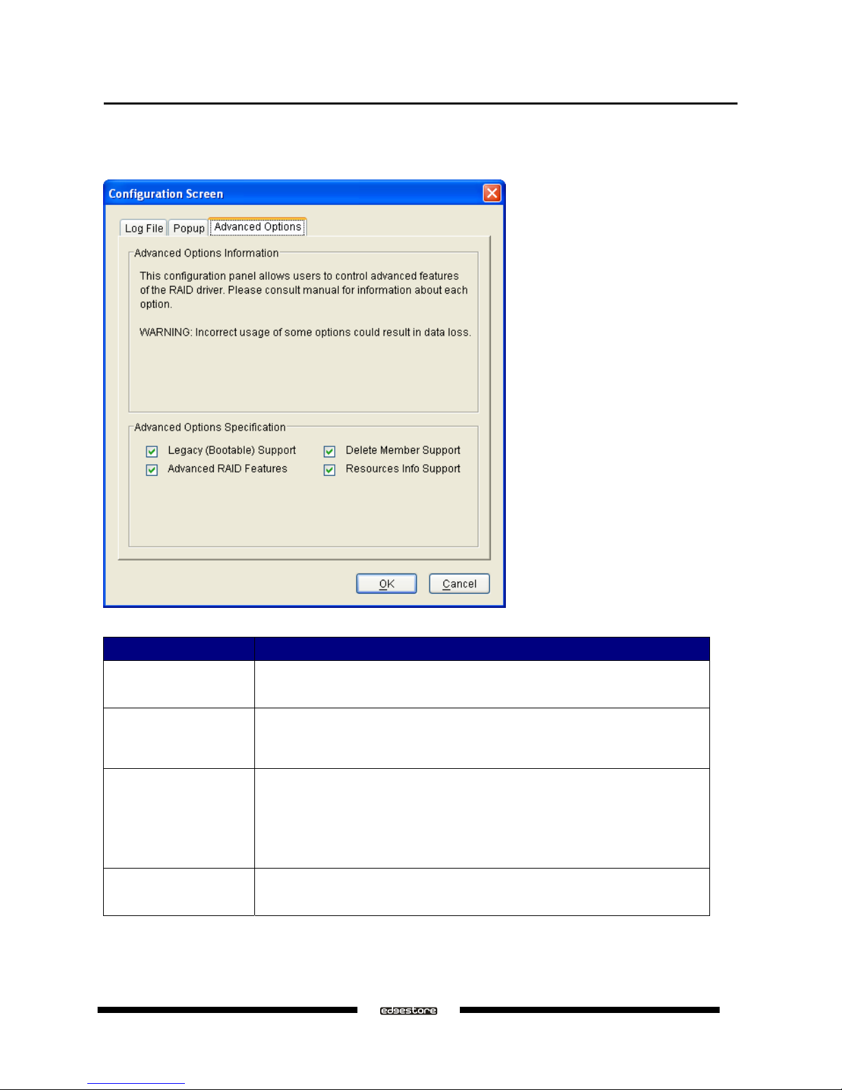
Advanced Options
The Advanced Options tab is used to control advanced features of the RAID driver. By default, all these advanced
options are disabled.
The Advanced Options tab allows you to enable the following advanced features.
FEATURE
EXPLANATION
Legacy (Bootable) Support
When this feature is selected, Legacy Support menu will be available in the menu bar.
Enables the Legacy Support menu to support RAID functions for legacy RAID groups
(available on Windows platforms only). See Legacy Support menu options.
Delete Member Support
When this feature is selected, Delete Member menu item will be available under the
Device menu. Enables the Delete Member option on the Device menu to delete a
member from RAID 1 (Mirrored), RAID 5 (Parity RAID), and RAID 10 (Striped and
Mirrored) groups. See Delete Member menu option.
Advanced RAID Features
When this feature is selected and user selects to create RAID group, if the RAID group
to be created is fault tolerance group (RAID 1, RAID 5, or RAID 10), user will be able to
select Improper Shutdown Policy in the Create RAID Group dialog box. Enables the
selection of an Improper Shutdown Policy (including Check-Pointing and Dirty Parity
handling) in the Create RAID Group dialog box when the selected RAID Group type is a
fault-tolerant configuration (Mirrored, Mirrored/Striped and Parity RAID). This feature is
not supported for Legacy RAID groups.
Resources Info Support
When this feature is selected, Resources menu item will be available under the Window
menu. Enables the Resources option on the Window menu for debugging purposes.
See Resources menu option.
4.3.2 EXIT
This command terminates the SATARAID5 program.
DAS401 User’s Manual
Ver.071015
81
Page 82
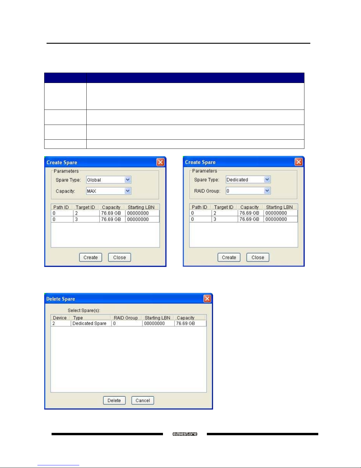
4.3.3 CREATE SPARE
This command displays a dialog box to let user create spare drive, user needs to select the following parameters:
PARAMETER DESCRIPTION
Spare Type
Choose one of:
• Global - If the spare drive is for all RAID groups in the system.
• Dedicated - If the spare drive is dedicated to the specified RAID group.
Capacity
If you select Global for the Spare Type, current options from a list of capacity are from 128 MB to
100 GB, HALF and MAX.
RAID Group
If you select Dedicated for the Spare Type, please selected RAID group to which this spare drive
is dedicated.
Device Segment Select one device segment from the available spare type only.
4.3.4 DELETE SPARE
This menu option displays a dialog box to select (highlight) one or more spare drives to delete.
Ver.071015
DAS401 User’s Manual
82
Page 83
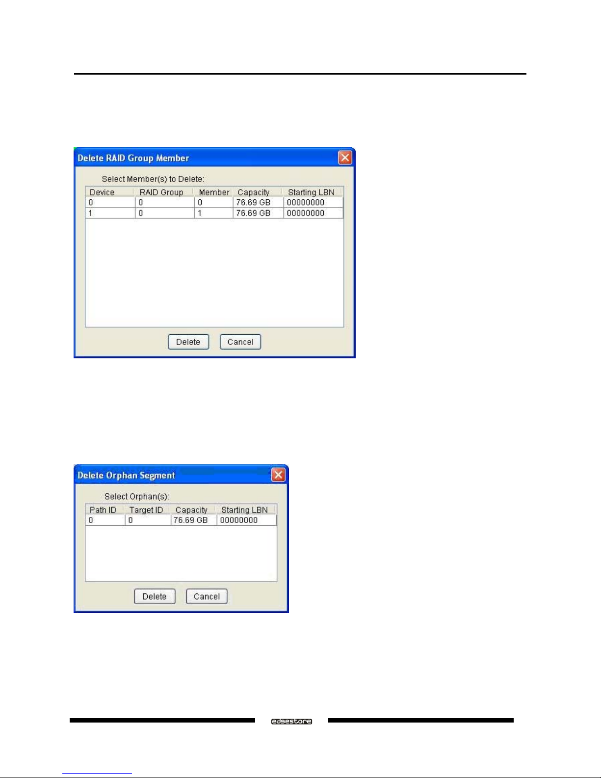
4.3.5 DELETE MEMBER
This menu option displays a dialog box to select (highlight) RAID group members to delete. Because RAID 0 is
not fault tolerant, RAID 0 members are no t shown in the list.
Note: Deleting members will demote the RAID group to a non-fault-tolerant RAID group.
4.3.6 DELETE ORPHAN
This menu option displays a dialog box to select (highlight) orphan segments to delete. An orphan segment is part
of a RAID group that cannot access other segments within the same RAID group. When a member of a RAID
group fails in a severe manner (such as a loss of power or a complete hard disk failure), it becomes an orphan.
This command displays the Delete Orphan Segment window to show all orphan segments and allow user to
delete selected orphan segm ents.
4.3.7 MAKE PASS-THRU
This menu option is not available in this product.
DAS401 User’s Manual
Ver.071015
83
Page 84
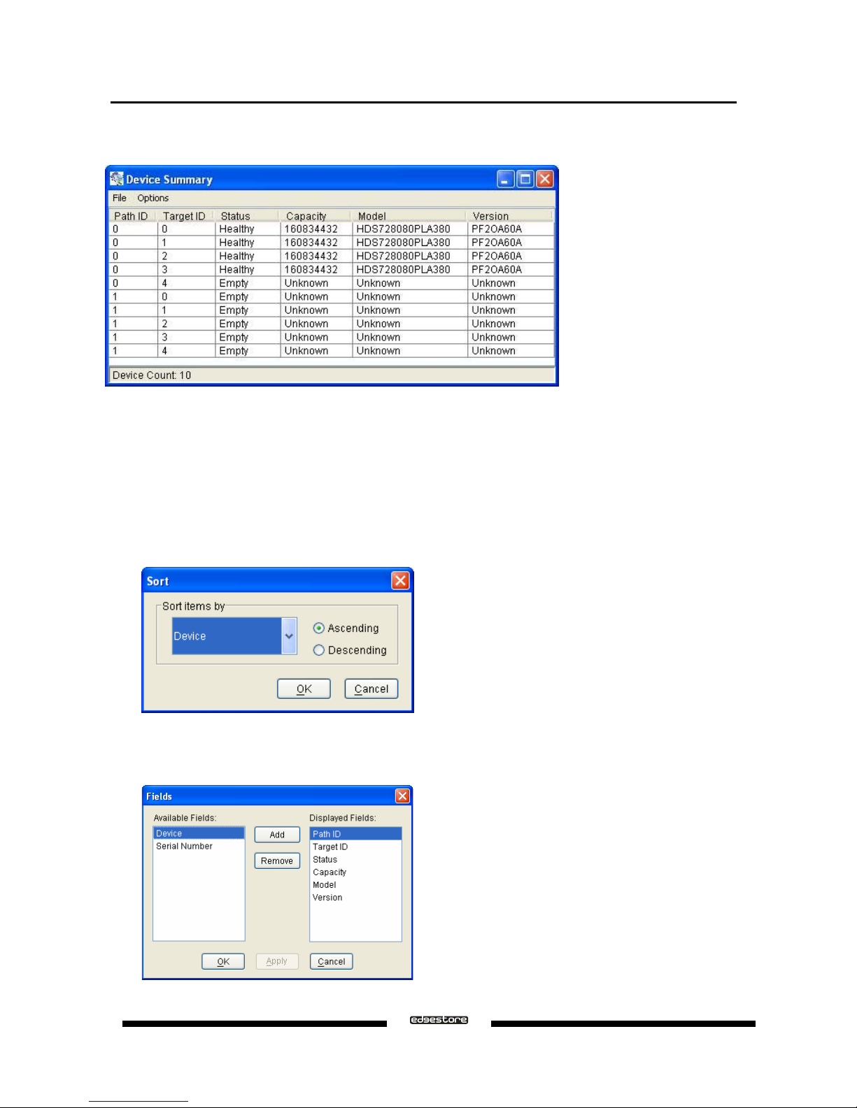
4.3.8 DEVICE SUMMARY
This command displays the Segment Summary window to show all physical devices’ segments.
The Segment Summary window has its own menu bar. All options available via the menu bar are shown below
File Options
Exit Sorting…
Fields…
Exit
This command closes the Task Summary window.
Sorting
This command sorts the rows based on the selected field.
Fields
This command displays a dialog box to let user choose which fields will be shown in the Segment
Summary window.
Ver.071015
DAS401 User’s Manual
84
Page 85
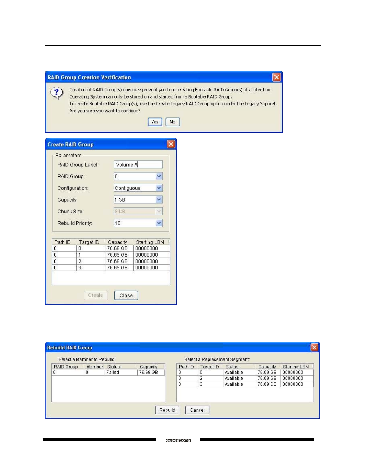
4.3.9 CREATE RAID GROUP
This command displays a dialog box to let user verify a raid type than display Create RAID Group dialog box.
4.3.10 REBUILD RAID GROUP
This command displays a dialog box to let user choose a replacement segment to rebuild a non-fault tolerant
RAID group.
DAS401 User’s Manual
Ver.071015
85
Page 86
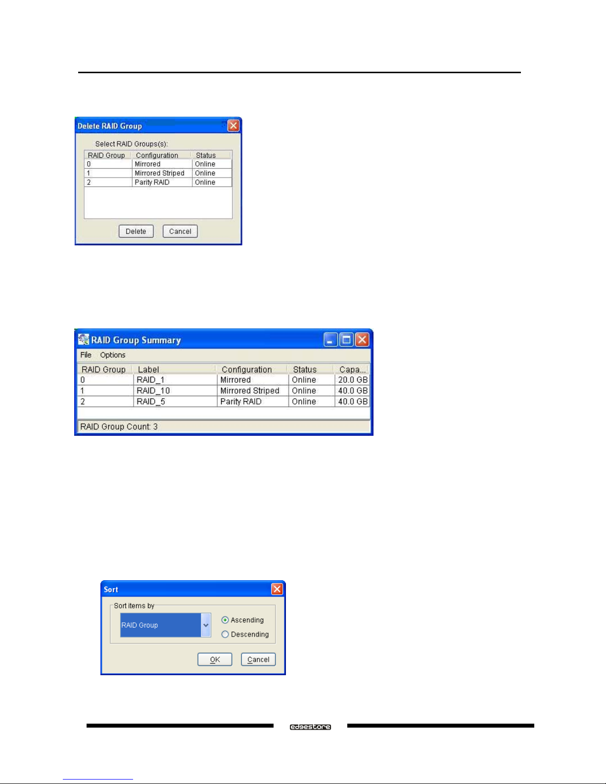
4.3.11 DELETE RAID GROUP
This command displays a dialog box to let user choose RAID groups to delete.
4.3.12 BRING RAID GROUP ONLINE
This menu option is not available in this product.
4.3.13 RAID GROUP SUMMARY
This command displays a dialog box to show all RAID groups’ group ID, configuration, and status.
The RAID Group Summary window has its own menu bar. All options available via the menu bar are shown below.
File Options
Exit Sorting…
Fields…
Exit
This command closes the RAID Group Summary window.
Sorting
This command displays a dialog box to let user choose up to 3 items to sort RAID group items in the RAID
Group list.
Ver.071015
DAS401 User’s Manual
86
Page 87
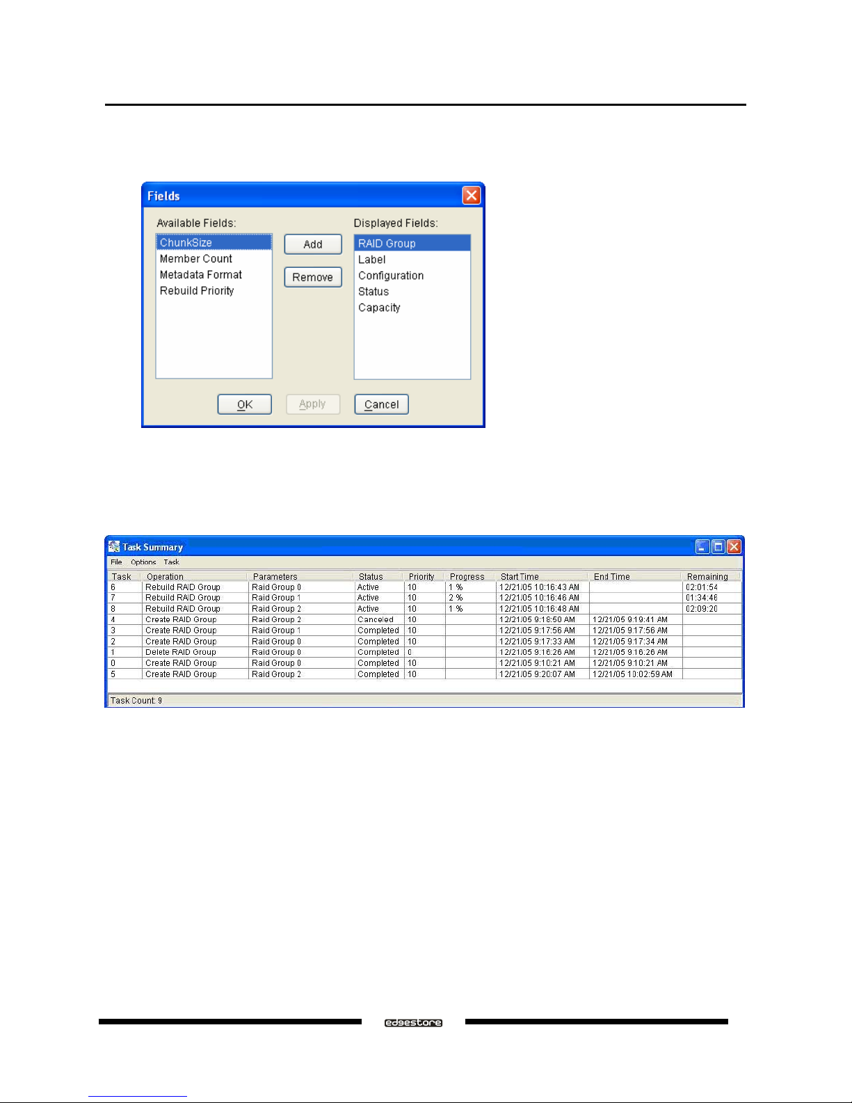
Fields
This command displays a dialog box to let user choose which fields will be shown in the RAID Group
Summary window.
4.3.14 TASK MANAGER
This command displays the Task Manager window. The Task Manager window lists all RAID and disk
management tasks that have been started and/or done. This window provides user the ability to schedule any
RAID and disk management operat ions including RAID group creation, rebuild, and test.
The Task Manager window has it’s own menu bar. All options available via the menu bar are shown below
File Options Task
Open… Sorting… Modify…
Save… Fields… Suspend…
Print…
Resume…
Exit
Cancel…
Delete…
Open
This option will be available in future revisions.
Save
This option will be available in future revisions.
DAS401 User’s Manual
Ver.071015
87
Page 88
Print
This option will be available in future revisions.
Exit
This command closes the Task Summary window.
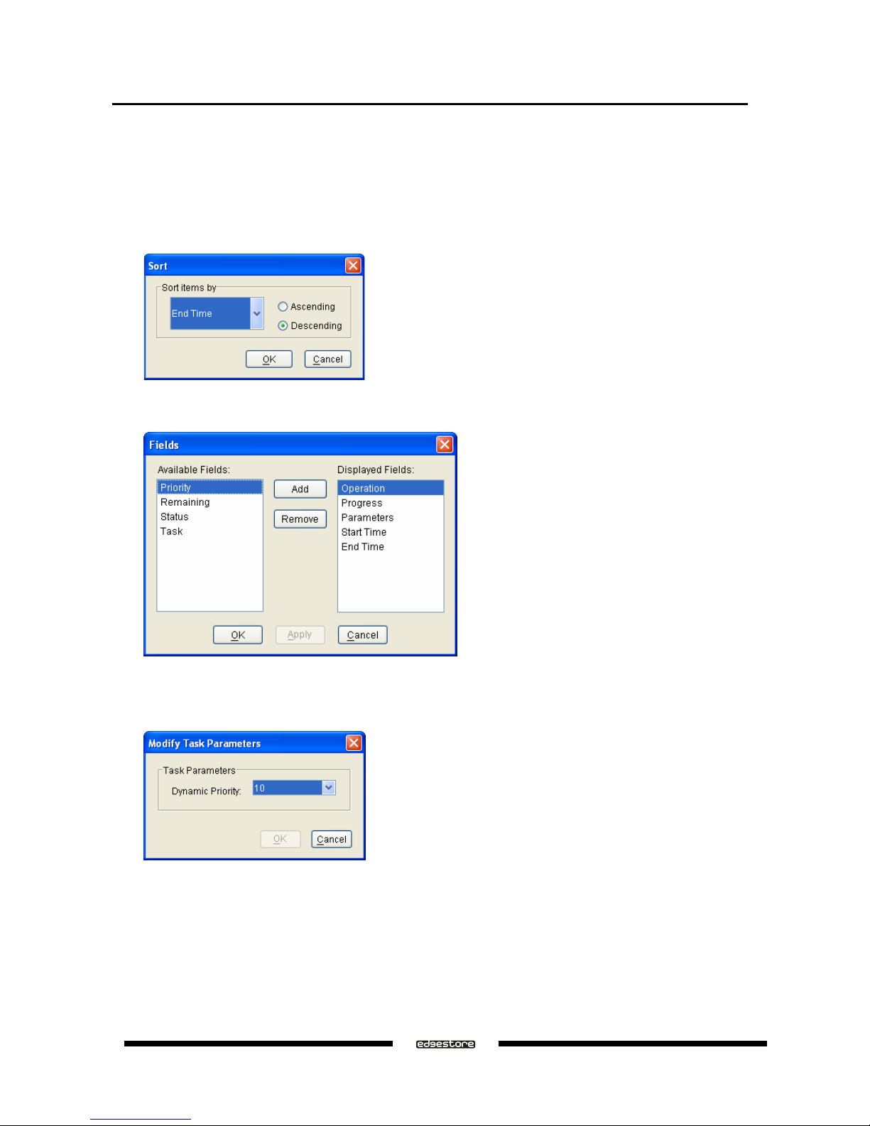
Sorting
This command displays a dialog box to let user choose up to 3 items to sort task items in the task list.
Fields
This command displays a dialog box to let user choose which fields will be shown in the task list.
Modify
This command allows user to modify parameters of the selected task items. The following is an example of
changing rebuild priority for a rebuild task.
Suspend
This command allows user to suspend the selected task items.
Resume
This command allows user to resume the suspended task items.
Ver.071015
DAS401 User’s Manual
88
Page 89
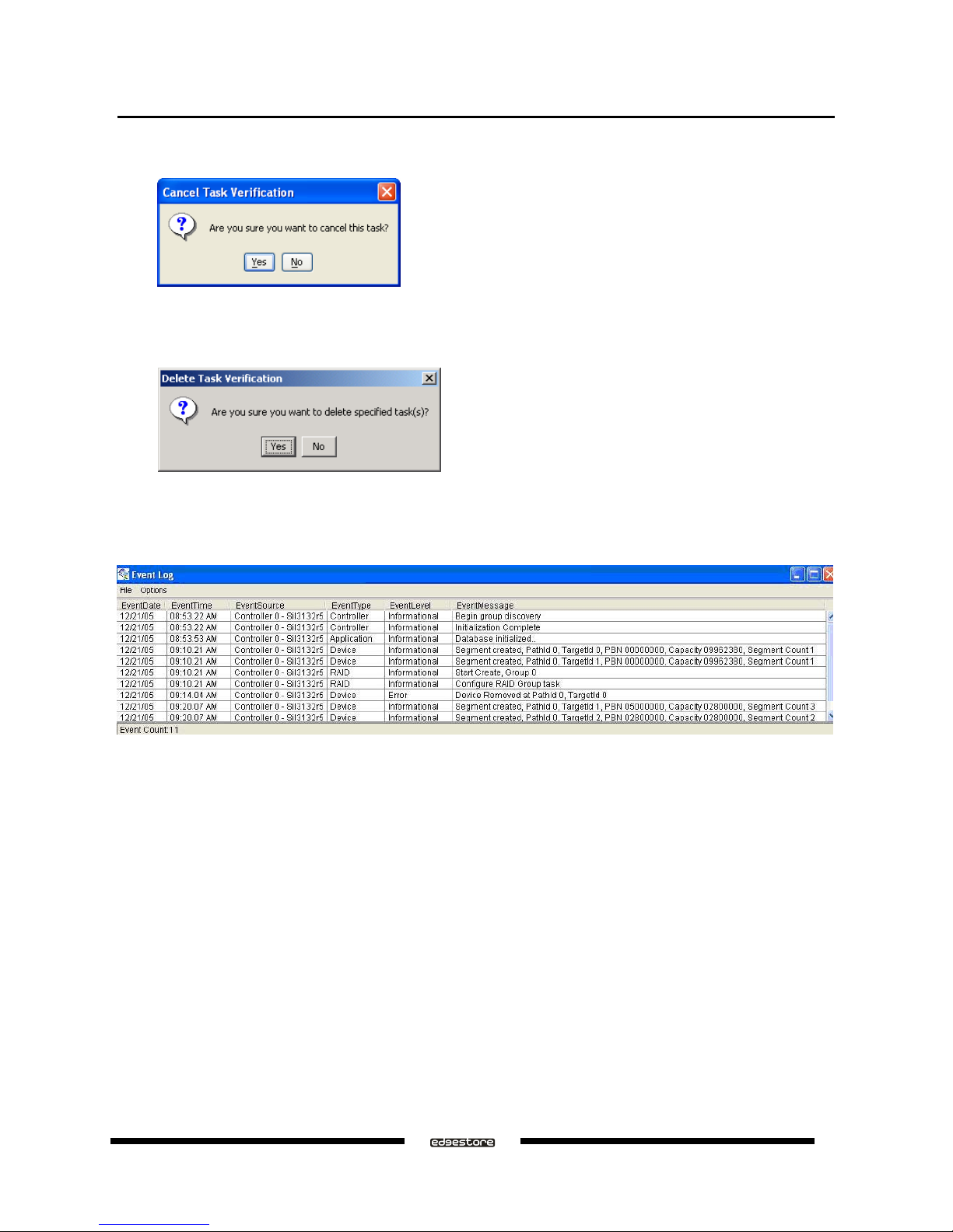
Cancel
This command allows user to cancel the selected task items.
Delete
This command displays a dialog box to let user delete the selected task items from the task list in Task
Summary window. The following dialog box will pop up to get confirmation from the user.
4.3.15 EVENT LOG
This command displays the Event Log window. The Event Log window displays SATA device-related events that
occur while SATARAID5 is running.
The Event Log window has it’s own menu bar. All options available via the menu bar are shown below
File Options
Exit Sorting…
Fields…
Exit
This command closes the Event Log window.
DAS401 User’s Manual
Ver.071015
89
Page 90
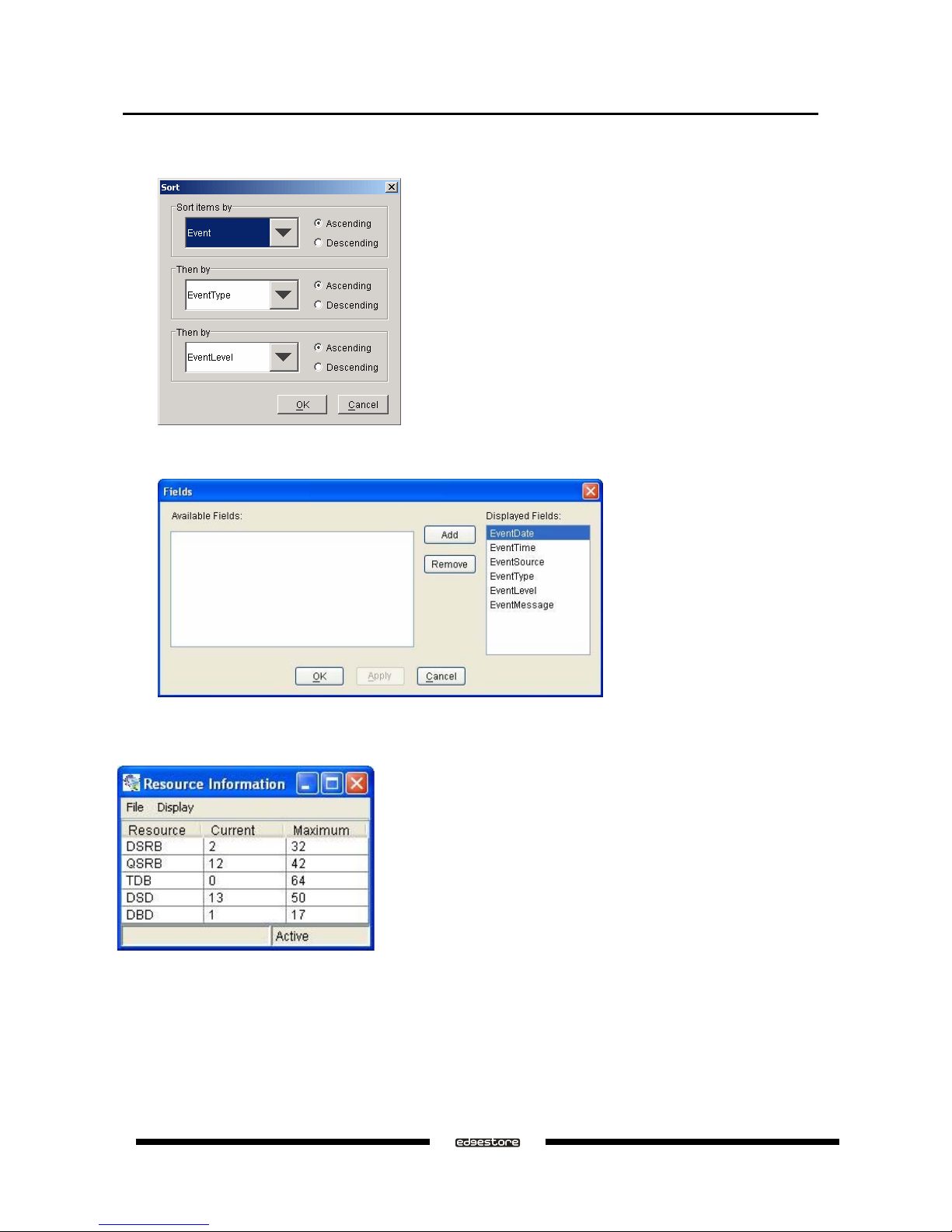
Sorting
This command displays a dialog box to let user choose up to 3 items to sort event items in the event log.
Fields
This command displays a dialog box to let user choose which fields will be shown in the event log.
4.3.16 RESOURCES
This command displays the Resource Information window. This feature is for debugging purpose only.
The Event Log window has it’s own menu bar. All options available via the menu bar are shown below
File Display
Exit Suspend
Resume
Exit
This command closes the Resources window.
Ver.071015
DAS401 User’s Manual
90
Page 91
Suspend
This command is to suspend the resources informantion.
Fields
This command is to resume the resources informantion.
4.3.17 CREATE LEGACY RAID GROUP
This menu option is not available in this product.
4.3.18 HELP TOPICS
This command opens an interactive help dialog using the standard Windows help interface.
This option will be available in future revisions.
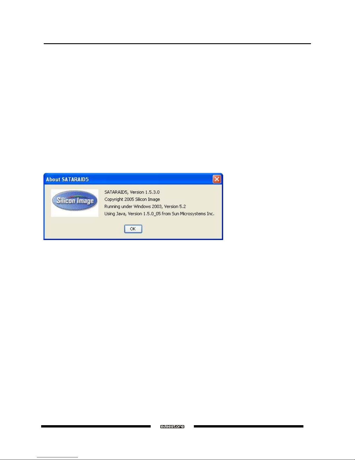
4.3.19 ABOUT
This command displays a dialog box with more information about the SATARAID5 program, including the revision
level.
DAS401 User’s Manual
Ver.071015
91
 Loading...