

Edge Ovens EDGE40, EDGE60 Installation & Operating Manual
MODELS: EDGE40 / EDGE60
INSTALLATION & O PERATING
MANUAL
FOR DOMESTIC AND STANDARD EXPORT OVENS
RETAIN THIS MANUAL FOR FUTURE REFERENCE
TO BE SERVICED BY AUTHORIZED PERSONS ONLY
MF&B RESTAURANT SYSTEMS, INC.
133 ICMI ROAD
DUNBAR, PA 15431
1-888-480-EDGE
P: (724) 628-3050
F: (724) 626-0247
WWW.EDGEOVENS.COM
Revision 1.1, December 04, 2008
EDGE40 / EDGE60 Installation and Operating Manual
SAFETY INFORMATION
WARNING
Improper installation, adjustment, alteration, servicing or
maintenance can result i n prope rty damage, injury, or death. Read
this entire manual and ensur e that you thoroughly understand all
instructions before installing, operating, or servi c ing this equipment.
WARNING
Do not store or use gasoline, cl e a ning solvent s , or any other material
that may emit flammable vapors nea r this or any other appliance.
NOTICE
Oven installation, including electrical and natural gas connections , oven
placement, and ventilation must comply with all applicable national and local
codes. National and local cod es sup ersede the recommendations, requirements,
and guidelines contained in the manual.
NOTICE
The purchaser of this equipment is required to prominently post instructions to
be followed should the user smell natural gas. This information shall be obtained
from the local natural gas supplier.
NOTICE
Installing any part(s) not provided by the Edge oven OEM shall void the warranty
and release the OEM from any and all liabilities.
IMPORTANT
Retain all shipping materials until you are certain that the oven has not been
damaged (either externally or internally) during shipment. Thoroughly inspect
the oven on receipt for both external and internal damage. It is solely the
customer's responsibility to report any shipping damage to the freight company.
NOTICE
The oven electrical wiring diagram is located inside the control compartme nt.
WARNING
Keep the appliance free and clear of combustibles.
ii Rev 1.1 December 04, 2008

EDGE40 / EDGE60 Installation and Operating Manual
WARNING
Do not obstruct the flow of combustion or ventilation air to and from the oven.
There should never be any obstructions on or around the oven that could hamper
the flow of combustion or ventilation air to or from the oven. Any changes to the
area where the oven is installed must not affect the combustion or ventilation air
to and from the oven.
iii Rev 1.1 December 04, 2008

EDGE40 / EDGE60 Installation and Operating Manual
Table of Contents
Section Page
SAFETY INFORMATION ...................................................................................................................... ii
OVEN COMPONENTS ........................................................................................................................... 1
OVEN CONTROLS ................................................................................................................................. 3
OVEN START-UP AND SHUTDOWN .................................................................................................. 4
OVEN VENTILATION ............................................................................................................................ 5
INSTALLATION INSTRUCTIONS ........................................................................................................ 6
SPECIFICATIONS EDGE40 ................................................................................................................. 23
SPECIFICATIONS EDGE60 ................................................................................................................. 25
WIRING DIAGRAM MODULATING.................................................................................................. 33
WIRING DIAGRAM ON-OFF .............................................................................................................. 34
RESTRAINT CABLE ............................................................................................................................ 35
MAINTENANCE ................................................................................................................................... 36
EDGE OVEN WARRANTY POLICY & PROCEDURE ...................................................................... 39
APPENDIX “A” ..................................................................................................................................... 42
COMPANY INFORMATION ................................................................................................................ 44
iv Rev 1.1 December 04, 2008

EDGE40 / EDGE60 Installation and Operating Manual
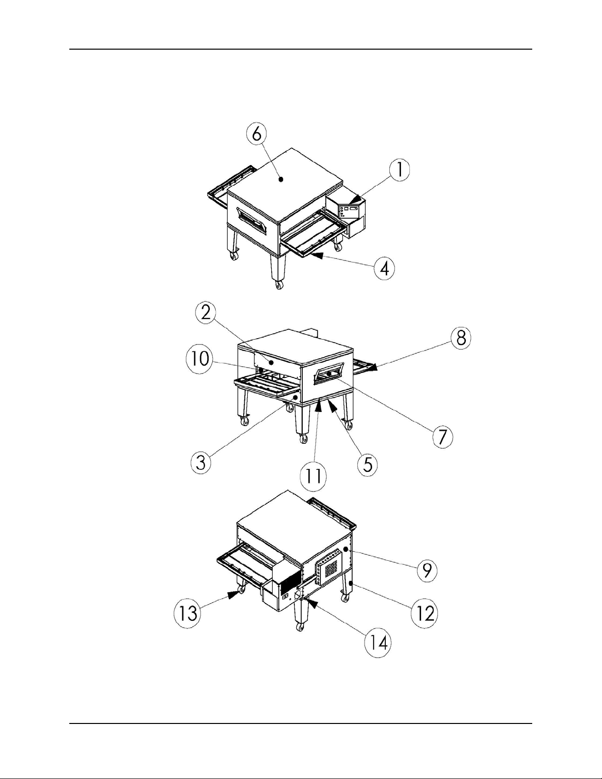
OVEN COMPONENTS
1.
Control Can Assembly:
gas control devices and burner.
2.
End Plug, Upper:
belt.
3.
End Plug, Lower:
conveyor belt.
4.
Conveyor Belt:
through the oven.
5.
Oven Base:
6.
Oven Lid:
oven insulation.
Supports and insulates the bottom of the oven.
Mounts to the top of the oven, fini s hes off the oven stack and covers the
Closes off the top half of the bake chamber, above the conveyor
Closes off the bottom half of the bake chamber, below the
Runs horizontally through the bake chamber; caries the product
Houses the operating controls for the oven and the natural
7.
Half-Bake Window:
(half bake time).
8.
Crumb Pan:
debris that falls through the conveyor belt.
9.
Back Assembly:
10.
Plenum Assembly:
monitor hot air temperature.
11.
Oven Bottom:
the oven insulation.
12.
Oven Legs:
to convenient working heights.
13.
Oven Casters:
installation and servicing.
14.
Restraining Device: Secures the oven base to the wall to avoid damage to gas and
electrical connections.
Located under both the entrance and exit of the conveyor belt, catches
Used with single- and double-stack configurations to raise lower oven
Opens to allow the product to be placed half way through oven
Closes off the back of the bake chamber.
Houses the hot air blower motor and fan, and thermocouples to
Mounts to the top of the oven base, seals off the stack and covers
Used on all oven configurations to allow moving the oven for
1 Rev 1.1 December 04, 2008
EDGE40 / EDGE60 Installation and Operating Manual
2 Rev 1.1 December 04, 2008
EDGE40 / EDGE60 Installation and Operating Manual
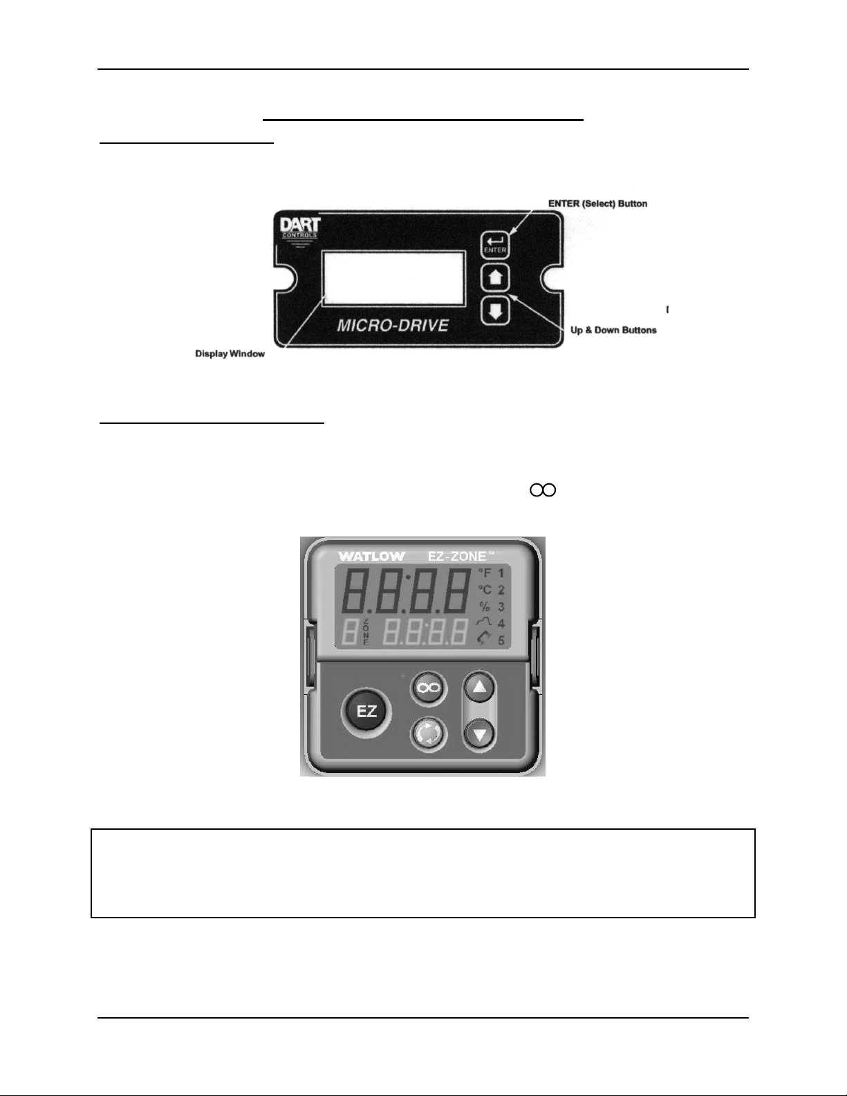
OVEN CONTROLS
Digital Speed Control: Sets the product baking time (conveyor speed) of the oven
between 3:00 to 30:00 minutes (MM:SS format). Pressing the up arrow (▲) key
increases the baking time, and pressing the down arrow (▼) decreases the baking time.
Figure 1: Digital Speed Control
Digital Temperature Control: Sets the oven temperature from 350˚ to 600 °F as
desired for the product being baked. Pressing the up arrow ( ▲) key increases the
baking temperature, and pressing the down arrow ( ▼) decreases the baking
temperature. The upper display shows the actual oven temperature, and the lower
display shows the oven temperature setting. Pressing the button resets the internal
over temperature alarm.
Figure 2: Digital Temperature Control
NOTE
Both the speed and temperature controls are preset at the factory. Contact an
authorized service agent or MF&B Restaurant Systems, Inc., for further information on
these controls and their factory settings.
3 Rev 1.1 December 04, 2008

EDGE40 / EDGE60 Installation and Operating Manual
OVEN START-UP AND SHUTDOWN
WARNING
This appliance is equipped with a three-prong (grounding) plug and
must be connected to a properly grounded three-prong receptacle.
This is to protect you from a possible s hock hazard.
DO NOT remove the grounding prong from this plug, or use any form
of adapter to plug the appli a nc e into a sta ndard two-prong receptacle.
OVEN START-UP
1. Turn on the OVEN FAN switch.
2. Set the TEMPERATURE CONTROL to the desired baking temperature.
3. Turn on the BURNER switch.
4. If the burner does not light within a few seconds, turn off the BURNER swi tch,
wait five minutes, and then return the BURNER switch to on.
5. Turn on the OVEN CONVEYOR.
6. Set the CONVEYOR SPEED control to the desired baking time.
7. Preheat the oven for 15 minutes before baking any product.
OVEN SHUTDOWN
1. Turn off the CONVEYOR switch.
2. Turn off the BURNER switch.
3. Turn off the OVEN FAN switch.
NOTE
In case of a power failure or interruption, turn all oven control switches to off and
remove all product from the oven. When power is restored, follow the instructions
above to re-start the oven.
NOTE
Oven is equipped with a cool down circuit. Oven fan will continue to operate until oven
temperature reaches 1 60˚F.
4 Rev 1.1 December 04, 2008

EDGE40 / EDGE60 Installation and Operating Manual
OVEN VENTILATION
IMPORTANT
This oven must be installed under a ventilation hood. The ventilation hood must
be installed in accordance with the Standard for Ventilation Control and Fire
Protection of Commercial Cooking Operations, NFPA 96.
IMPORTANT
• Gas ovens must have
a mechanically driven ventilation system.
• All local, national, or international codes
ventilation system for this appliance.
• All local, national, or international codes supersede any recommendations
found in this manual.
• Proper ventilation of this oven is the sole responsibility of the purchaser.
VENTILATION RECOMMENDATIONS
In some areas, code requires the installation of fire suppression equipment. This
equipment may not be mounted directly to the oven. Such mounting restricts
oven movement for service and may void the oven certification.
Canopy style hoods should extend beyond each end of the belt and the front of
the oven by no less than (6) inches.
The ventilation system must be vented outdoors and away from any entrance or
air intake vent.
Proper balance of exhaust and make-up air is critical in the design of a properly
functioning hood system.
must be
followed when installing the
Consult your hood manufacturer or ventilation engineer for pr oper hood s i z i ng
(minimum CFM rating).
5 Rev 1.1 December 04, 2008
EDGE40 / EDGE60 Installation and Operating Manual
INSTALLATION INSTRUCTIONS
IMPORTANT
US CUSTOMERS
Oven installation must comply with local codes or, if local codes do not exist,
with the National Fuel Gas Code, ANSI Z223.1/NFPA 54.
This appliance must be electrically grounded in accordance with local codes, or if
local codes do not exist, with the National Electrical Code, ANSI/NFPA 70.
When this appliance is installed with casters, it must be installed with the casters
supplied, a connector complying with ANSI Z21.69, a quick-disconnect device
complying with ANSI Z21.41, and a mechanism to limit movement of the
appliance without straining the connector or its associated piping system.
IMPORTANT
CANADIAN CU S TO MERS
Oven installation must comply with local codes or, if local codes do not exist, gas
oven installation must comply with the Natural Gas Installation Code, CAN/CGA-
B149.1, or the Propane Gas Installati on Code, CAN/CSA-B149-2, as applicable.
This appliance must be electrically isolated in accordance with local codes, or if
local codes do not exist, with the Canadian Electrical Code, CSA C22.2.
When this appliance is installed with casters, it must be installed with the casters
supplied, a connector complying with CAN/CGA-6.16, a quick-disconnect device
complying with CAN-6.9, and a mechanism to limit movement of the appliance
without straining the connector or its associated piping system.
NOTE
This appliance and its individual manual shutoff valves must be disconnected
from the gas supply piping system during any pressure testing of gas supply
piping at pressures exceeding 1/2 psi (3.5 KPa).
NOTE
The installer of this oven must contact local building and fire officials concerni ng
inspections and installation requirements of this oven and its ventilation system.
6 Rev 1.1 December 04, 2008

EDGE40 / EDGE60 Installation and Operating Manual
Ovens can be shipped two ways:
1. Option #1: Ovens shipped structurally pre-assembled.
A. This is the way most oven manufacturers ship their ovens.
B. Ovens will be shipped via common carrier with lift-gate service.
C. The oven will require final assembly of non-structural components.
D. Special lifting equipment may be requir ed for safe installation.
2. Option #2: Ovens shipped structurally unassembled.
A. This modular design method is new to the oven industry, and is used for all Edge
40 and 60 ovens. This design allows two-three people with basic mechanical
aptitude to safely assemble and install a single-, double-, or triple-stack of Edge
ovens using only a few simple hand tools.
B. The owner/installer will not require any special equipment for moving or installing
ovens shipped this way.
C. Ovens will be shipped via common carrier with lift-gate service.
D. Ovens will need to have some of the main structure (or body) assembled on site
by the installers. This includes bolting together the following components:
• Oven Base
• Oven Plenum Assembly
• Oven Control Can Assembly
• Oven Face
• Oven Top
E. The oven will require final assembly of non-structural components.
7 Rev 1.1 December 04, 2008

EDGE40 / EDGE60 Installation and Operating Manual
Installation Ins t ructions – Option #1 (Pre-Assembled)
TOOLS REQUIRED:
(1) Genie SLA or similar lift
(4) 7” Cribbing Block
(1) 4-wheel dolly, pallet jack, or similar.
1. Remove the oven from the shipping crate. Inspect the oven for concealed shipping
damage before continuing.
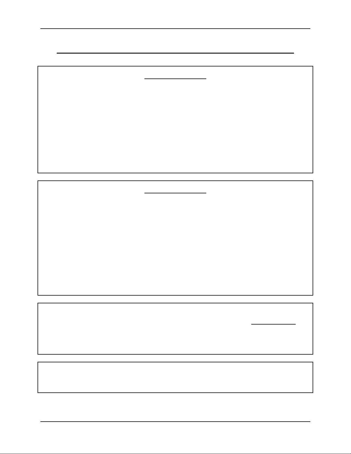
2. For single- or double-stack installation only, install the casters onto the oven legs.
(Figure 3)
Figure 3
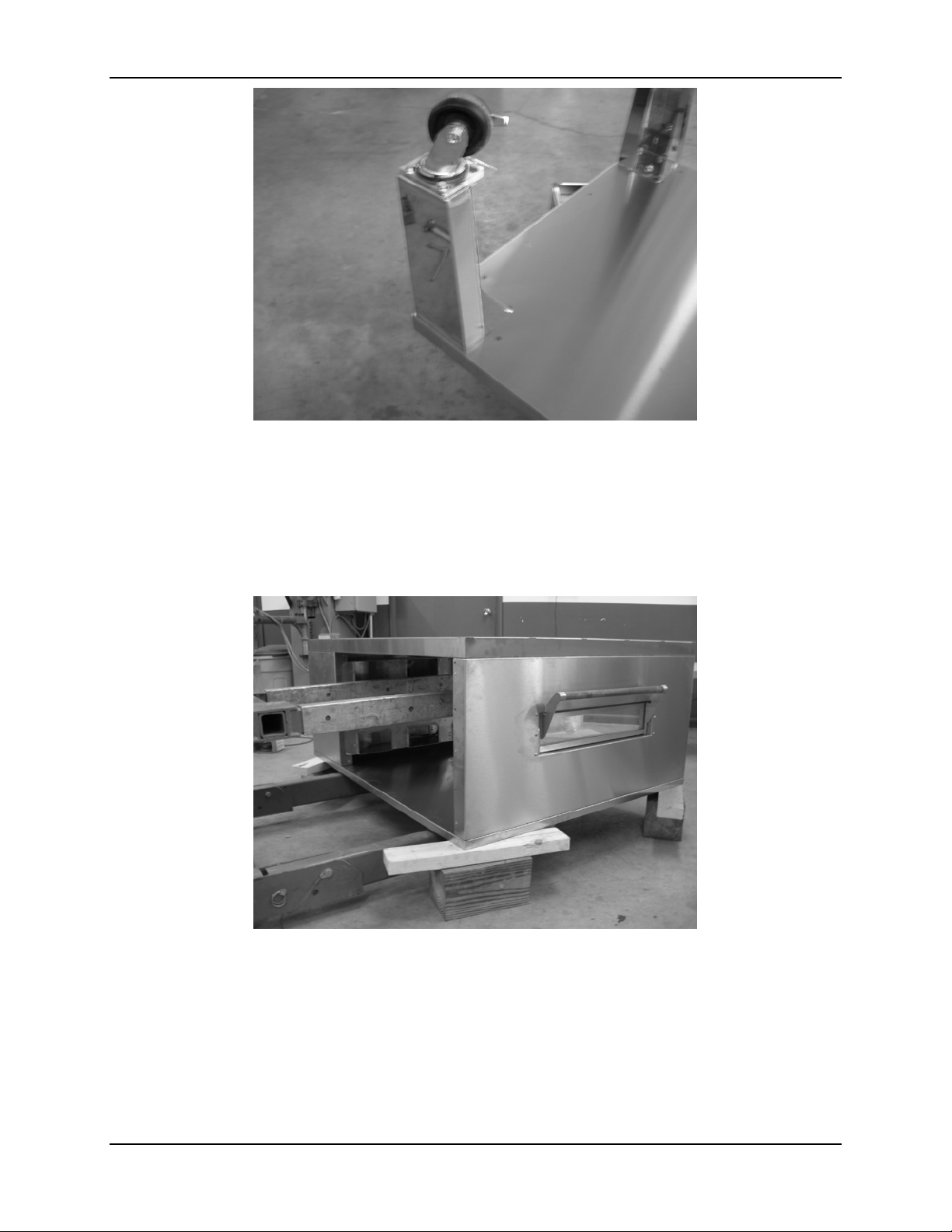
3. For single- or double-stack installation only, install the oven legs (with casters) onto
the oven base. For triple-stack installation only, install the casters directly onto the
oven base.(Figure 4)
8 Rev 1.1 December 04, 2008
EDGE40 / EDGE60 Installation and Operating Manual
Figure 4
4. Set the oven base assembly flat on its casters near the final installation area.
5. Tilt the oven assembly over so that the oven bottom is sitting flat on the floor. If
using a Genie SLA type lift, support the oven about seven inches above the floor
using cribbing blocks on all four corners to allow clearance for the Genie
base.(Figure 5)
Figure 5
6. Lift and place the oven onto the base using a Genie SLA or similar type of lifting
device.(Figure 6)
9 Rev 1.1 December 04, 2008
EDGE40 / EDGE60 Installation and Operating Manual
Figure 6
7. For a triple-stack installation only (no legs), support the oven base about seven
inches above the floor using cribbing blocks on all four corners to al l ow clearance for
the Genie base while stacking the ovens.
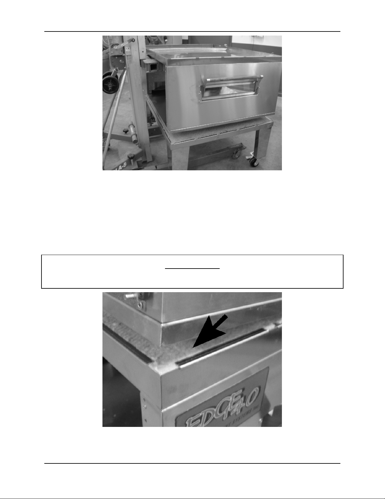
8. Repeat steps 5 and 6 with the next oven(s), stacking each oven on top of the lower
oven. Ensure that the one (1) inch connecting lip on the bottom of each upper oven
fits securely over the lower oven. (Figure 7)
WARNING
Do not place your hands or fingers under the connecting lip. The edge of the
connecting lip is sharp and can cause severe cuts or perhaps loss of a finger.
Figure 7
10 Rev 1.1 December 04, 2008

EDGE40 / EDGE60 Installation and Operating Manual
9. When done assembling the stack, place the oven lid on top of the fi nal ov en. Sec ur e
the lid using (4) 10-32 x 3/8 screws included in the hardware kit.
11 Rev 1.1 December 04, 2008
 Loading...