

MODELS: EDGE40 / EDGE60
INSTALLATION & O PERATING
MANUAL
FOR DOMESTIC AND STANDARD EXPORT OVENS
RETAIN THIS MANUAL FOR FUTURE REFERENCE
TO BE SERVICED BY AUTHORIZED PERSONS ONLY
MF&B RESTAURANT SYSTEMS, INC.
133 ICMI ROAD
DUNBAR, PA 15431
1-888-480-EDGE
P: (724) 628-3050
F: (724) 626-0247
WWW.EDGEOVENS.COM
Revision 1.1, December 04, 2008
EDGE40 / EDGE60 Installation and Operating Manual
SAFETY INFORMATION
WARNING
Improper installation, adjustment, alteration, servicing or
maintenance can result i n prope rty damage, injury, or death. Read
this entire manual and ensur e that you thoroughly understand all
instructions before installing, operating, or servi c ing this equipment.
WARNING
Do not store or use gasoline, cl e a ning solvent s , or any other material
that may emit flammable vapors nea r this or any other appliance.
NOTICE
Oven installation, including electrical and natural gas connections , oven
placement, and ventilation must comply with all applicable national and local
codes. National and local cod es sup ersede the recommendations, requirements,
and guidelines contained in the manual.
NOTICE
The purchaser of this equipment is required to prominently post instructions to
be followed should the user smell natural gas. This information shall be obtained
from the local natural gas supplier.
NOTICE
Installing any part(s) not provided by the Edge oven OEM shall void the warranty
and release the OEM from any and all liabilities.
IMPORTANT
Retain all shipping materials until you are certain that the oven has not been
damaged (either externally or internally) during shipment. Thoroughly inspect
the oven on receipt for both external and internal damage. It is solely the
customer's responsibility to report any shipping damage to the freight company.
NOTICE
The oven electrical wiring diagram is located inside the control compartme nt.
WARNING
Keep the appliance free and clear of combustibles.
ii Rev 1.1 December 04, 2008

EDGE40 / EDGE60 Installation and Operating Manual
WARNING
Do not obstruct the flow of combustion or ventilation air to and from the oven.
There should never be any obstructions on or around the oven that could hamper
the flow of combustion or ventilation air to or from the oven. Any changes to the
area where the oven is installed must not affect the combustion or ventilation air
to and from the oven.
iii Rev 1.1 December 04, 2008

EDGE40 / EDGE60 Installation and Operating Manual
Table of Contents
Section Page
SAFETY INFORMATION ...................................................................................................................... ii
OVEN COMPONENTS ........................................................................................................................... 1
OVEN CONTROLS ................................................................................................................................. 3
OVEN START-UP AND SHUTDOWN .................................................................................................. 4
OVEN VENTILATION ............................................................................................................................ 5
INSTALLATION INSTRUCTIONS ........................................................................................................ 6
SPECIFICATIONS EDGE40 ................................................................................................................. 23
SPECIFICATIONS EDGE60 ................................................................................................................. 25
WIRING DIAGRAM MODULATING.................................................................................................. 33
WIRING DIAGRAM ON-OFF .............................................................................................................. 34
RESTRAINT CABLE ............................................................................................................................ 35
MAINTENANCE ................................................................................................................................... 36
EDGE OVEN WARRANTY POLICY & PROCEDURE ...................................................................... 39
APPENDIX “A” ..................................................................................................................................... 42
COMPANY INFORMATION ................................................................................................................ 44
iv Rev 1.1 December 04, 2008

EDGE40 / EDGE60 Installation and Operating Manual
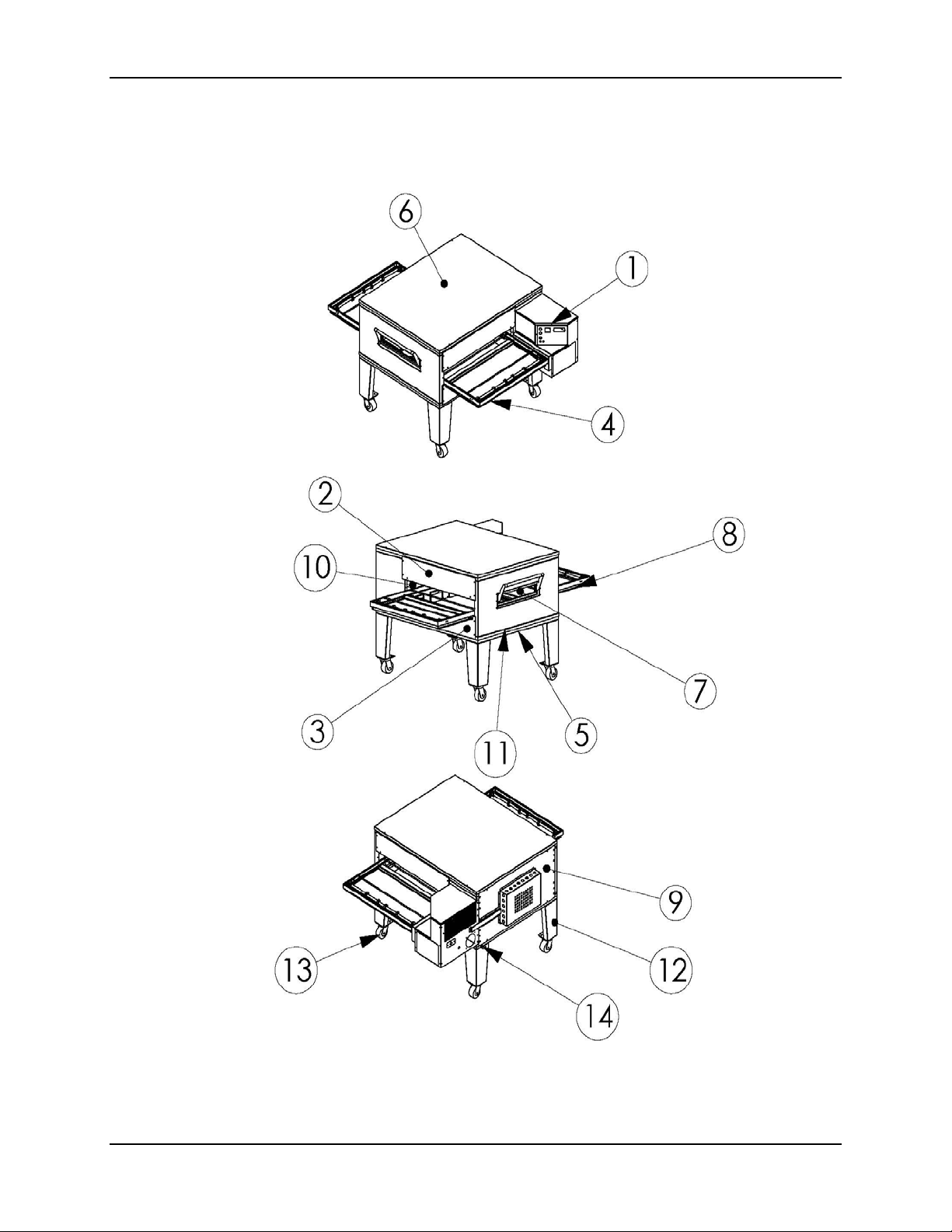
OVEN COMPONENTS
1.
Control Can Assembly:
gas control devices and burner.
2.
End Plug, Upper:
belt.
3.
End Plug, Lower:
conveyor belt.
4.
Conveyor Belt:
through the oven.
5.
Oven Base:
6.
Oven Lid:
oven insulation.
Supports and insulates the bottom of the oven.
Mounts to the top of the oven, fini s hes off the oven stack and covers the
Closes off the top half of the bake chamber, above the conveyor
Closes off the bottom half of the bake chamber, below the
Runs horizontally through the bake chamber; caries the product
Houses the operating controls for the oven and the natural
7.
Half-Bake Window:
(half bake time).
8.
Crumb Pan:
debris that falls through the conveyor belt.
9.
Back Assembly:
10.
Plenum Assembly:
monitor hot air temperature.
11.
Oven Bottom:
the oven insulation.
12.
Oven Legs:
to convenient working heights.
13.
Oven Casters:
installation and servicing.
14.
Restraining Device: Secures the oven base to the wall to avoid damage to gas and
electrical connections.
Located under both the entrance and exit of the conveyor belt, catches
Used with single- and double-stack configurations to raise lower oven
Opens to allow the product to be placed half way through oven
Closes off the back of the bake chamber.
Houses the hot air blower motor and fan, and thermocouples to
Mounts to the top of the oven base, seals off the stack and covers
Used on all oven configurations to allow moving the oven for
1 Rev 1.1 December 04, 2008
EDGE40 / EDGE60 Installation and Operating Manual
2 Rev 1.1 December 04, 2008
EDGE40 / EDGE60 Installation and Operating Manual
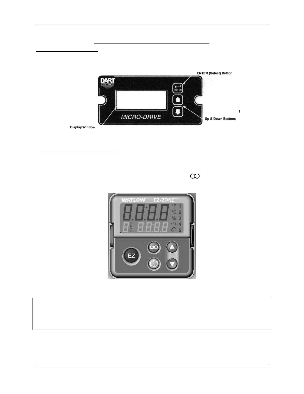
OVEN CONTROLS
Digital Speed Control: Sets the product baking time (conveyor speed) of the oven
between 3:00 to 30:00 minutes (MM:SS format). Pressing the up arrow (▲) key
increases the baking time, and pressing the down arrow (▼) decreases the baking time.
Figure 1: Digital Speed Control
Digital Temperature Control: Sets the oven temperature from 350˚ to 600 °F as
desired for the product being baked. Pressing the up arrow ( ▲) key increases the
baking temperature, and pressing the down arrow ( ▼) decreases the baking
temperature. The upper display shows the actual oven temperature, and the lower
display shows the oven temperature setting. Pressing the button resets the internal
over temperature alarm.
Figure 2: Digital Temperature Control
NOTE
Both the speed and temperature controls are preset at the factory. Contact an
authorized service agent or MF&B Restaurant Systems, Inc., for further information on
these controls and their factory settings.
3 Rev 1.1 December 04, 2008

EDGE40 / EDGE60 Installation and Operating Manual
OVEN START-UP AND SHUTDOWN
WARNING
This appliance is equipped with a three-prong (grounding) plug and
must be connected to a properly grounded three-prong receptacle.
This is to protect you from a possible s hock hazard.
DO NOT remove the grounding prong from this plug, or use any form
of adapter to plug the appli a nc e into a sta ndard two-prong receptacle.
OVEN START-UP
1. Turn on the OVEN FAN switch.
2. Set the TEMPERATURE CONTROL to the desired baking temperature.
3. Turn on the BURNER switch.
4. If the burner does not light within a few seconds, turn off the BURNER swi tch,
wait five minutes, and then return the BURNER switch to on.
5. Turn on the OVEN CONVEYOR.
6. Set the CONVEYOR SPEED control to the desired baking time.
7. Preheat the oven for 15 minutes before baking any product.
OVEN SHUTDOWN
1. Turn off the CONVEYOR switch.
2. Turn off the BURNER switch.
3. Turn off the OVEN FAN switch.
NOTE
In case of a power failure or interruption, turn all oven control switches to off and
remove all product from the oven. When power is restored, follow the instructions
above to re-start the oven.
NOTE
Oven is equipped with a cool down circuit. Oven fan will continue to operate until oven
temperature reaches 1 60˚F.
4 Rev 1.1 December 04, 2008

EDGE40 / EDGE60 Installation and Operating Manual
OVEN VENTILATION
IMPORTANT
This oven must be installed under a ventilation hood. The ventilation hood must
be installed in accordance with the Standard for Ventilation Control and Fire
Protection of Commercial Cooking Operations, NFPA 96.
IMPORTANT
• Gas ovens must have
a mechanically driven ventilation system.
• All local, national, or international codes
ventilation system for this appliance.
• All local, national, or international codes supersede any recommendations
found in this manual.
• Proper ventilation of this oven is the sole responsibility of the purchaser.
VENTILATION RECOMMENDATIONS
In some areas, code requires the installation of fire suppression equipment. This
equipment may not be mounted directly to the oven. Such mounting restricts
oven movement for service and may void the oven certification.
Canopy style hoods should extend beyond each end of the belt and the front of
the oven by no less than (6) inches.
The ventilation system must be vented outdoors and away from any entrance or
air intake vent.
Proper balance of exhaust and make-up air is critical in the design of a properly
functioning hood system.
must be
followed when installing the
Consult your hood manufacturer or ventilation engineer for pr oper hood s i z i ng
(minimum CFM rating).
5 Rev 1.1 December 04, 2008
EDGE40 / EDGE60 Installation and Operating Manual
INSTALLATION INSTRUCTIONS
IMPORTANT
US CUSTOMERS
Oven installation must comply with local codes or, if local codes do not exist,
with the National Fuel Gas Code, ANSI Z223.1/NFPA 54.
This appliance must be electrically grounded in accordance with local codes, or if
local codes do not exist, with the National Electrical Code, ANSI/NFPA 70.
When this appliance is installed with casters, it must be installed with the casters
supplied, a connector complying with ANSI Z21.69, a quick-disconnect device
complying with ANSI Z21.41, and a mechanism to limit movement of the
appliance without straining the connector or its associated piping system.
IMPORTANT
CANADIAN CU S TO MERS
Oven installation must comply with local codes or, if local codes do not exist, gas
oven installation must comply with the Natural Gas Installation Code, CAN/CGA-
B149.1, or the Propane Gas Installati on Code, CAN/CSA-B149-2, as applicable.
This appliance must be electrically isolated in accordance with local codes, or if
local codes do not exist, with the Canadian Electrical Code, CSA C22.2.
When this appliance is installed with casters, it must be installed with the casters
supplied, a connector complying with CAN/CGA-6.16, a quick-disconnect device
complying with CAN-6.9, and a mechanism to limit movement of the appliance
without straining the connector or its associated piping system.
NOTE
This appliance and its individual manual shutoff valves must be disconnected
from the gas supply piping system during any pressure testing of gas supply
piping at pressures exceeding 1/2 psi (3.5 KPa).
NOTE
The installer of this oven must contact local building and fire officials concerni ng
inspections and installation requirements of this oven and its ventilation system.
6 Rev 1.1 December 04, 2008

EDGE40 / EDGE60 Installation and Operating Manual
Ovens can be shipped two ways:
1. Option #1: Ovens shipped structurally pre-assembled.
A. This is the way most oven manufacturers ship their ovens.
B. Ovens will be shipped via common carrier with lift-gate service.
C. The oven will require final assembly of non-structural components.
D. Special lifting equipment may be requir ed for safe installation.
2. Option #2: Ovens shipped structurally unassembled.
A. This modular design method is new to the oven industry, and is used for all Edge
40 and 60 ovens. This design allows two-three people with basic mechanical
aptitude to safely assemble and install a single-, double-, or triple-stack of Edge
ovens using only a few simple hand tools.
B. The owner/installer will not require any special equipment for moving or installing
ovens shipped this way.
C. Ovens will be shipped via common carrier with lift-gate service.
D. Ovens will need to have some of the main structure (or body) assembled on site
by the installers. This includes bolting together the following components:
• Oven Base
• Oven Plenum Assembly
• Oven Control Can Assembly
• Oven Face
• Oven Top
E. The oven will require final assembly of non-structural components.
7 Rev 1.1 December 04, 2008
EDGE40 / EDGE60 Installation and Operating Manual
Installation Ins t ructions – Option #1 (Pre-Assembled)
TOOLS REQUIRED:
(1) Genie SLA or similar lift
(4) 7” Cribbing Block
(1) 4-wheel dolly, pallet jack, or similar.
1. Remove the oven from the shipping crate. Inspect the oven for concealed shipping
damage before continuing.
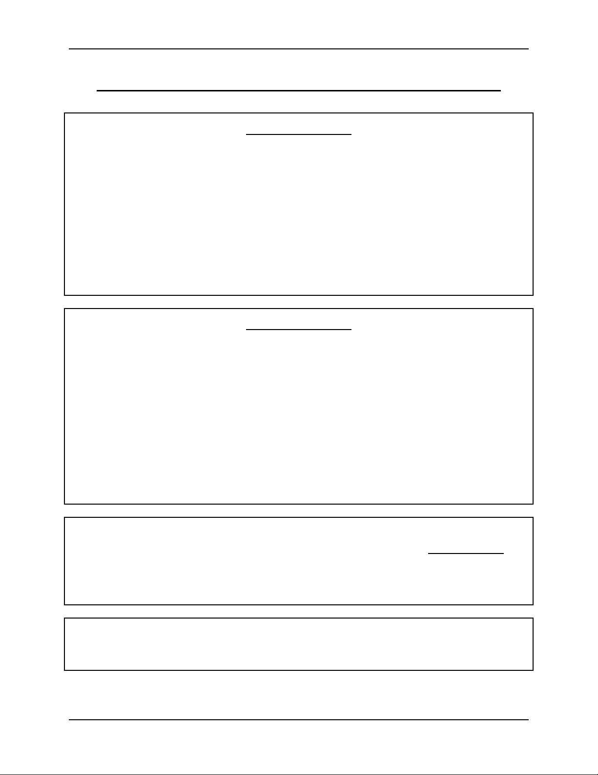
2. For single- or double-stack installation only, install the casters onto the oven legs.
(Figure 3)
Figure 3
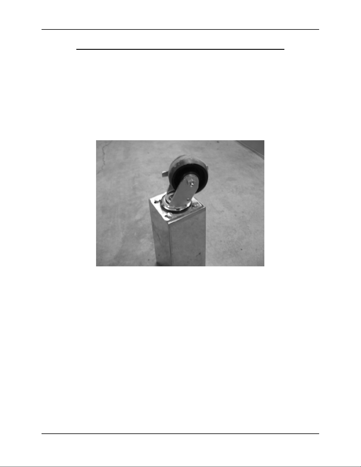
3. For single- or double-stack installation only, install the oven legs (with casters) onto
the oven base. For triple-stack installation only, install the casters directly onto the
oven base.(Figure 4)
8 Rev 1.1 December 04, 2008
EDGE40 / EDGE60 Installation and Operating Manual
Figure 4
4. Set the oven base assembly flat on its casters near the final installation area.
5. Tilt the oven assembly over so that the oven bottom is sitting flat on the floor. If
using a Genie SLA type lift, support the oven about seven inches above the floor
using cribbing blocks on all four corners to allow clearance for the Genie
base.(Figure 5)
Figure 5
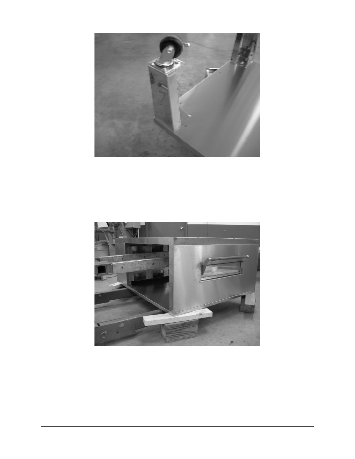
6. Lift and place the oven onto the base using a Genie SLA or similar type of lifting
device.(Figure 6)
9 Rev 1.1 December 04, 2008
EDGE40 / EDGE60 Installation and Operating Manual
Figure 6
7. For a triple-stack installation only (no legs), support the oven base about seven
inches above the floor using cribbing blocks on all four corners to al l ow clearance for
the Genie base while stacking the ovens.
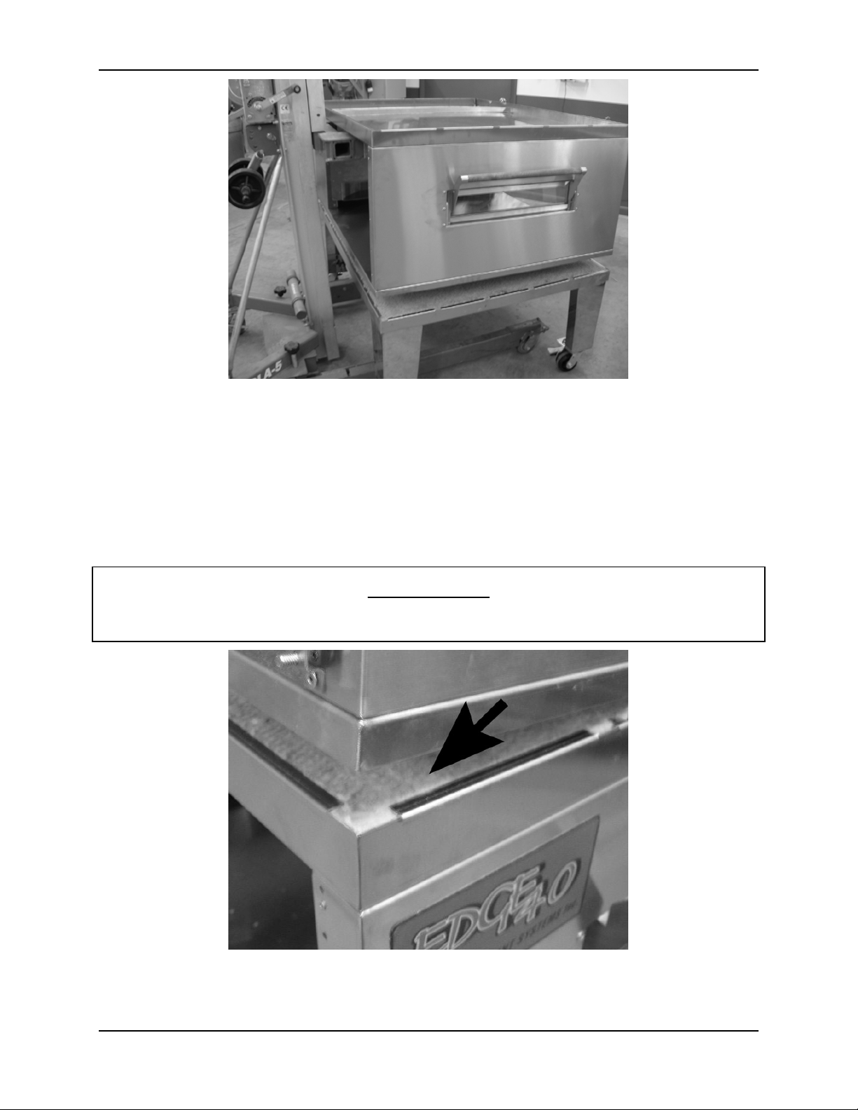
8. Repeat steps 5 and 6 with the next oven(s), stacking each oven on top of the lower
oven. Ensure that the one (1) inch connecting lip on the bottom of each upper oven
fits securely over the lower oven. (Figure 7)
WARNING
Do not place your hands or fingers under the connecting lip. The edge of the
connecting lip is sharp and can cause severe cuts or perhaps loss of a finger.
Figure 7
10 Rev 1.1 December 04, 2008

EDGE40 / EDGE60 Installation and Operating Manual
9. When done assembling the stack, place the oven lid on top of the fi nal ov en. Sec ur e
the lid using (4) 10-32 x 3/8 screws included in the hardware kit.
11 Rev 1.1 December 04, 2008

EDGE40 / EDGE60 Installation and Operating Manual
Installation Ins t ructions – Option #2 (Installer-Assembled)
TOOLS REQUIRED:
(1) 9/16 socket or wrench
(1) 7/16 socket or wrench
(1) Set of alignment tools (supplied)
(1) Phillips screw driver
(1) Slotted screwdriver
1. Remove all items from the shipping crate. Inspect each item for shipping damage
before continuing.
2. For single- or double-stack installation only, install the casters onto the oven legs.
(Figure 3)
3. For single- or double-stack installation only, install the oven legs (with casters) onto
the oven base. For triple-stack installation only, install the casters directly onto the
oven base.(Figure 4)
4. Set the oven base assembly flat on its casters near the final installation area.
NOTE
The oven back is shipped assembled to protect the blower motor fan from
damage during shipping.
CAUTION
Be careful not to bend or otherwise damage the blower fan. Any damage to the
blower fan will result in premature failure of the blower motor bearings.
5. Locate the oven back (hot air plenum with blower motor and fan). Remove the 3/816 x 3/4 bolts holding the oven back (blower motor/fan assembly) to the plenum,
then separate the oven back and plenum assemblies. Set the blower motor/fan
assembly and hardware aside for use lat er.
NOTE
The hardware kit included with your oven contains alignment tools and all
hardware necessary to assemble your oven.
During assemble; use the alignment tools in the smaller punched holes to locate
proper placement of components. Leave the mounting bolts snug, but do not
tighten fully, until all bolts are installed. This will help align all components
properly.
6. Set the hot air plenum on a level work surface with plenum finger face facing up.
7. Set the oven bottom onto the plenum (connecting lip facing up), align the mounting
holes, and secure it to the plenum us ing 3/8-16 x 3/4 bolts.
12 Rev 1.1 December 04, 2008

EDGE40 / EDGE60 Installation and Operating Manual
8. Set the oven front (half-bake window upside down) under the other end of the oven
bottom, align the mounting holes, and secure it to the oven bottom using 3/8-16 x
3/4 bolts. (Figure 8)
Figure 8
9. Fully tighten all bolts passing through the oven bottom.
10. Turn the par tially assembled oven over.
11. Remove the insulation from the oven top and set it aside. Note how the insulation
was installed to aid reinstallation.
12. Set the oven top (connecting lip facing up) onto the plenum/oven bottom/oven front
assembly, and align the mounting holes. Secure it to the plenum and oven front
using 3/8-16 x 3/4 mounting bolts and alig nm ent pi ns .(Figure 9)
Figure 9
13 Rev 1.1 December 04, 2008

EDGE40 / EDGE60 Installation and Operating Manual
13. Firmly tighten all bolts passing through the oven top.
14. Reinstall the insulation in the oven top.
WARNING
Do not place your hands or fingers under the connecting lip. The edge of the
connecting lip is sharp and can cause severe cuts or perhaps loss of a finger.
15. Lift and set the oven assembly on the oven base. Ensure that the connecting lip fits
over the oven base.(Figure 10)
Figure 10
16. Lift the control can into position, and run the two thermocouple leads into the hot air
plenum through the small hole provided.(Figure 11)
Figure 11
14 Rev 1.1 December 04, 2008

EDGE40 / EDGE60 Installation and Operating Manual
17. Set the control can into position, insert alignment pins, and secure it to the oven
using 1/4-20 x 3/4 inch bolts.(Figure 12)
Figure 12
18. Insert the thermocouples into the plenum bracket provided. This bracket is made of
spring steel and may be pinched together to allow thermocouples to pass thru both
holes.(Figure 13)
Figure 13
19. Reinstall the oven back removed earlier (being careful not to damage fan blade) and
secure it to the plenum with 3/8-16 x 3/4 inch bolts.
15 Rev 1.1 December 04, 2008

EDGE40 / EDGE60 Installation and Operating Manual
20. Connect the blower motor plug and install the wire chase and motor cover.(Figure
14)
Figure 14
21. Repeat steps 5 through 20 to complete assembling the stack. Ensure that the
connecting lip for each oven fits securely over the oven below.
22. Set the lid on top of the final oven and secure it using (4) 10-32 x 3/8 machine
screws.
16 Rev 1.1 December 04, 2008

EDGE40 / EDGE60 Installation and Operating Manual
B C A
Installation Ins t ructions – Finger Assemblies (Options #1 and #2)
1. All EDGE ovens are shipped with a total of eight (8) finger assemblies per oven.
Each finger assembly consists of three (3) parts:
A. Housing
B. Inner Columnating Panel
C. Outer Cover
Figure 15
2. Your finger assemblies have been shipped from the factory with a set pattern based
on the type of product to be baked. In most cases, the only difference will be the
inner columnating panel. Refer to the finger location decal located on the front of
your oven to determine which finger assembly to place in each finger position of your
oven.
3. Working from the control side of the oven, set the first pair of upper and lower finger
assemblies into place by sliding them into the oven with the narrow end slightly
raised (to avoid the front finger holders). Align the wider (open) end of the finger
over the finger opening in the plenum wall, and lower the narrow end into the front
finger holder.(Figure 16)
17 Rev 1.1 December 04, 2008

EDGE40 / EDGE60 Installation and Operating Manual
Figure 16
4. Repeat step 3 until all eight (8)-finger assemblies have been installed.
18 Rev 1.1 December 04, 2008

EDGE40 / EDGE60 Installation and Operating Manual
Installation Ins t ructions – End Plugs (Options #1 and #2)
1. All EDGE ovens have four (4) end plug assemblies. Each oven contains two (2) top
and two (2) bottom end plugs. The top end plugs can be identified by the baffle
mounting holes located on either end.
2. Install the bottom end plugs first by fitting them into the openings in the sides of the
bake chamber. The non-insulated part of the baffle is oriented downward on the
bottom end plugs. Tighten the thumbscrews by hand (do not use pliers to
tighten).(Figure 17)
Figure 17
3. Install the top end plugs as in step 2 above except the non-insulated part of the
baffle is oriented upward. Tighten the thumbscrews by hand only (do not use pliers
to tighten).(Figure 18)
Figure 18
19 Rev 1.1 December 04, 2008

EDGE40 / EDGE60 Installation and Operating Manual
Installation Ins t ructions – Conveyor (Options #1 and #2)
1. Conveyor installation is easier to perform using two people. Unfold the conveyor
and lay it flat on the floor. Secure the hinge locking mechanism with the screws
provided in the hardware kit. (
Figure 19)
Figure 19
2. Working from the drive side of the oven, gently set the non-drive end of the conveyor
into the bake chamber between the upper and lower end plugs.(Figure 20)
Figure 20
3. Tilt the conveyor upward slightly and slide the conveyor through the bake chamber
until the far end starts out the opposite side of the bake chamber.
4. Lift the conveyor from both ends and slide it through the bake chamber slightly past
its control side stops. This allows room to attach the conveyor drive chain over the
drive sprocket.(Figure 21)
20 Rev 1.1 December 04, 2008

EDGE40 / EDGE60 Installation and Operating Manual
Figure 21
5. Install the drive chain over the conveyor drive sprocket. Pull the conveyor back out
of the control side of the bake chamber until the locking rails on each end of the
conveyor lock into place. This also locks the drive chain onto the conveyor drive
sprocket.
6. The conveyor drive chain is adjusted at the factory prior to shipment. To tighten the
drive chain (if required), loosen the four (4) bolts securing the conveyor drive motor
to the side of the control can, slide the drive-end sprocket towards the bake chamber
to increase the chain tension, then retighten the four (4) bolts to lock the motor in
position.
7. Slide the chain guard cover down between the control can and the drive belt frame
and onto its guide pins.(Figure 22)
Figure 22
21 Rev 1.1 December 04, 2008

EDGE40 / EDGE60 Installation and Operating Manual
8. Insert the crumb pans into the rails underneath the belt frame. Solid crumb pans are
used in single or bottom oven belts. Perforated crumb pans are used in second and
third oven belts.(Figure 23)
Figure 23
Installation Ins t ructions – Final Connections (Options #1 and #2)
Final installation of gas and electrical connections should be performed by an
authorized service company or a locally licensed electrician and plumber.
Gas pressure on this oven will need to be checked and set to specifications listed
in this manual.
WARNING
Always check for leaks after making any gas supply piping connections or
performing any service on the oven.
22 Rev 1.1 December 04, 2008

EDGE40 / EDGE60 Installation and Operating Manual
SPECIFICATIONS EDGE40
Minimum Clearances:
Oven Back to Wall .............................................................
Control Side Conveyor to Wall .........................................
Non-Control Side Conveyor to Wall .................................
Dimensions:
Overall Height – Single-Stack ...........................................
Belt .................................................................................
Overall Height – Double-Stack ..........................................
Belt, top oven ................................................................
Overall Height – Triple-Stack ............................................
Belt, top oven ................................................................
Length .................................................................................
Depth ...................................................................................
Belt Width ...........................................................................
Electrical Specifications:
6.0”
6.0”
6.0”
42.21”
29.94”
56.29”
44.29”
68.56”
56.45”
75.25”
57.07”
32.00”
Operating Voltage ..............................................................
Phase ..................................................................................
Frequency ...........................................................................
Current Draw ......................................................................
Shipping Weight
Single Oven ........................................................................
Double Oven .......................................................................
Triple Oven .........................................................................
*estimate weights only
120 Vac
Single
60 Hz
5.5 Amps
TBD
TBD
TBD
23 Rev 1.1 December 04, 2008

EDGE40 / EDGE60 Installation and Operating Manual
Gas Supply Specifications
Modulating Burner (Standard & High Pressure H.P.)
Natural Gas Supply
STANDARD
Orifice Diameter ........................................
Supply Pressure .......................................
Manifold Pressure .....................................
HIGH PRESSURE (made after 4/01/10)
Orifice Diameter……………………………
Supply Pressure........................................
Manifold Pressure…..................................
Liquefied Petroleum (LP Supply)
Orifice diameter ........................................
Supply Pressure .......................................
Manifold Pressure .....................................
On-Off Burner
Natural Gas Supply
Orifice ..................................................................
Supply Pressure ................................................
.191”
4.5-8” WC
4.5” WC
.177”
7-11” WC
6.0” WC
.120”
10-13” WC
10” WC
.201”
3.5-7” WC
Manifold Pressure ..............................................
Liquefied Petroleum (LP Supply)
Orifice ..................................................................
Supply Pressure ................................................
Manifold Pressure ..............................................
3.5” WC
.120”
10-13” WC
10” WC
24 Rev 1.1 December 04, 2008

EDGE40 / EDGE60 Installation and Operating Manual
SPECIFICA TI ONS EDGE60
Minimum Clearances:
Oven Back to Wall .............................................................
Control Side Conveyor to Wall .........................................
Non-Control Side Conveyor to Wall .................................
Dimensions:
Overall Height – Single-Stack ...........................................
Belt .................................................................................
Overall Height – Double-Stack ..........................................
Belt, top oven ................................................................
Overall Height – Triple-Stack ............................................
Belt, top oven ................................................................
Length .................................................................................
Depth ...................................................................................
Belt Width ...........................................................................
Electrical Specifications:
6.0”
6.0”
6.0”
42.21”
29.94”
56.29”
44.29”
68.56”
56.45”
93.90”
57.07”
32.00”
Operating Voltage ..............................................................
Phase ..................................................................................
Frequency ...........................................................................
Current Draw ......................................................................
120 Vac
Single
60 Hz
5.5 Amps
Shipping Weight
Single Oven ........................................................................
Double Oven .......................................................................
Triple Oven .........................................................................
*estimate weights only
25 Rev 1.1 December 04, 2008
TBD
TBD
TBD

EDGE40 / EDGE60 Installation and Operating Manual
Gas Supply Specifica ti ons
Modulating Burner (Standard & High Pressure H.P.)
Natural Gas Supply
STANDARD
Orifice diameter .............................................
Supply Pressure ...........................................
Manifold Pressure .........................................
HIGH PRESSURE (made after 4/01/10)
Orifice Diameter……………………………
Supply Pressure........................................
Manifold Pressure…..................................
Liquefied Petroleum (LP Supply)
Orifice diameter .................................................
Supply Pressure ................................................
Manifold Pressure ..............................................
On-Off Burner
Natural Gas Supply
Orifice ..................................................................
.209”
4.5-8” WC
4.5” WC
.199”
7-11” WC
6.0” WC
.136”
10-13” WC
10” WC
.209”
Supply Pressure ................................................
Manifold Pressure ..............................................
Liquefied Petroleum (LP Supply)
Orifice ..................................................................
Supply Pressure ................................................
Manifold Pressure ..............................................
26 Rev 1.1 December 04, 2008
3.5-7” WC
3.5” WC
.136”
10-13” WC
10” WC

EDGE40 / EDGE60 Installation and Operating Manual
27 Rev 1.1 December 04, 2008

EDGE40 / EDGE60 Installation and Operating Manual
28 Rev 1.1 December 04, 2008

EDGE40 / EDGE60 Installation and Operating Manual
29 Rev 1.1 December 04, 2008

EDGE40 / EDGE60 Installation and Operating Manual
30 Rev 1.1 December 04, 2008

EDGE40 / EDGE60 Installation and Operating Manual
31 Rev 1.1 December 04, 2008

EDGE40 / EDGE60 Installation and Operating Manual
32 Rev 1.1 December 04, 2008

EDGE40 / EDGE60 Installation and Operating Manual
WIRING DIAGRAM MODULATING
Insert PDF of EDGE Modulating Wiring Diagram
33 Rev 1.1 December 04, 2008

EDGE40 / EDGE60 Installation and Operating Manual
WIRING DIAGRAM ON-OFF
Insert PDF of EDGE On-Off Wiring Diagram
34 Rev 1.1 December 04, 2008

EDGE40 / EDGE60 Installation and Operating Manual
RESTRAINT CABLE
IMPORTANT
OVENS EQUIPPED WITH CASTERS:
(1) The installation shall be made using a connector that complies with the
standard Connectors for Movable Gas Appliances, ANSI Z21.69 (CSA 6.16)
and a quick-disconnect that complies with the standard Quick-Disconnect
Devices for use with Gas Fuel, ANSI Z21.41 (CSA 6.9).
(2) Adequate means must be provided to limit movement of the appliance
without depending on the connector, quick-disconnect device, or associated
piping to limit appliance movement.
(3) The restraining device must be attached to the mounting eye located on the
left side of the oven base assembly.
All EDGE ovens are equipped with casters, and a restraint cable must be installed to
limit movement of the oven without straining the gas or electrical connections. One end
of the restraint cable is anchored to the wall, and the other end is anchored to the
mounting eye located on the left side of the oven base assembly.
Ensure that the restraint cable limits movement of the oven so that no strain is placed
on either the gas supply quick-disconnect fitting or the electrical power cord.
After connecting the restraint cable, move the oven into its final position and lock the
casters.
Whenever any maintenance or service is performed and the restraint must be
disconnected, ensure that it is reconnected as soon as the oven is returned to its normal
installed position.
WARNING
Use only the cord set supplied by the oven OEM, or a direct replacement cord set
purchased from the oven OEM. Other cord sets may present a fire and/or electric
shock hazard.
35 Rev 1.1 December 04, 2008

EDGE40 / EDGE60 Installation and Operating Manual
MAINTENANCE
WARNING
Turn off the oven, disconnect the gas supply line, and unplug the electrical cord
(or lock out the electrical supply) before doing any cleaning or service work on
the oven.
To prevent personal injury from moving parts or electrical shock, do not try to
clean or disassemble any part of the oven with power applied and until the oven
is completely cooled down.
IMPORTANT
Before performing oven maintenance:
• Turn off the oven.
• Allow the oven to complete its cool down cycle.
• Turn off the electrical supply to the oven or unplug the power cord from the
receptacle.
• If the oven must be moved, close the gas supply shutoff valve, disconnect the
gas supply line at the oven, and unlock the casters so the oven can be moved
safely.
After performing oven maintenance:
• Return the oven to its original location and lock the casters.
• If the restraint cable was disconnected to move the oven, reconnect it now.
• Reconnect the gas supply line and open the gas supply shutoff valve. Test
the gas supply connections for leaks.
• Reconnect the electrical supply or plug the power cord into its receptacle.
• The oven is now ready for normal startup and use.
CAUTION
• Never use a water hose, pressure washer, or steam cleaner on ovens.
• Never use metal scrapers, razor blades, steel wool, scouring pads, or any
other ferrous abrasives when cleaning ovens.
36 Rev 1.1 December 04, 2008

EDGE40 / EDGE60 Installation and Operating Manual
Daily Maintenance
• Clean the exterior of the oven using a mild detergent solution and a soft cloth.
Always clean in the direction of the grain to avoid visible scratches.
• Clean the glass window in the half-bake door using a soft cloth and mild detergent
solution.
• Remove and clean all crumb pa ns.
Monthly Maintenance
• Clean the exterior of the oven using a mild detergent solution and a soft cloth.
Always clean in the direction of the grain to avoid visible scratches.
• Clean the glass window in the half-bake door using a soft cloth and mild deter gent
solution.
• Remove and clean all crumb pans.
• Clean the conveyor using a stiff-bristle nylon brush to remove loose debris and food
particles.
• Remove the main fan motor cover, vacuum out any debris lodged in the motor
cooling ports, then reinstall the cover.
Quarterly Maintenance
• Perform all monthly maintenance tasks.
• Remove the conveyor drive chain cover and drive chain.
• Remove the conveyor belt assembly from the bake chamber.
• Remove the oven end plugs.
• Ensure that each finger is marked and is listed on the finger location decal so that
each finger can be reinstalled in the proper location.
• Vacuum the inside of the bake chamber to remove all loose debris.
• Clean the inside of the oven, the oven end plugs, and the conveyor drive chain cover
using a soft cloth and a mild detergent solution. Do not immerse in water.
• If possible, clean the oven fingers and conveyor assembly outside using a pressure
washer or steam cleaner. These components can also be cleaned using a stiffbristle nylon brush and a mild detergent solution.
• Allow all removed components to dry thoroughly before reinstallation.
• Reinstall components into oven:
– Reinstall fingers in appropriate locations.
– Reinstall oven end plugs.
– Reinstall the conveyor belt assembly.
– Reinstall the conveyor drive chain and drive chain cover.
37 Rev 1.1 December 04, 2008

EDGE40 / EDGE60 Installation and Operating Manual
IMPORTANT
Ensure that each finger assembly is reinstalled into the same location they were
removed from to avoid altering the baking characteristics of your oven.
WARNING
Any maintenance or service performed inside of the control can assembly or
other than listed in this manual should be performed by an authorized service
company to avoid oven damage.
WARNING
Following any maintenance, service work, or adjustments to the oven:
• Ensure that the ventilation system is working properly.
• Test for gas supply leaks.
• Visually inspect the oven to make sure it has been reassembled correctly.
38 Rev 1.1 December 04, 2008

EDGE40 / EDGE60 Installation and Operating Manual
EDGE OVEN WARRANTY POLICY &
PROCEDURE
The following Warranty Policy and Procedure is the only warranty made by MF&B Res taura nt Syst ems
Inc (MF&B), with respect to EDGE CONVEYOR OVENS manufactured by MF&B.
MF&B DISCLAIMS ALL OTHER WARRANTIES, EXPRESSED OR IMPLIED, INCLUDING BUT NOT
LIMITED TO ANY IMPLIED WARRANTY OF MERCHANTABILITY OR WARRANTY OF FITNESS FOR
A PARTICULAR PURPOSE.
1.0 WARRANTY POLICY
1.1 MF&B warrants to the original purchaser that each new oven will be free of proven defects in
material and workmanship under normal use and service for a period of 24 months from the date of
installation or 26 months from the date of shipm ent, whic he ver oc c urs firs t.
1.2 This warranty is extended to the original purchaser only and is not transferable.
1.3 The term “customer” as used in this Warranty Policy and Procedure refers to the original purchaser
of a new unit from MF&B or from any MF&B authorized dealer. This warranty extends only to
customer.
1.4 This warranty shall not apply if the oven or any part thereof is subjected to misuse, abuse,
negligence, alteration, improper installation, improper operation, operation outside of design limits,
accident or casualty.
1.5 The unit and its crating must be inspected upon arrival. Damage during shipping must be reported
to the carrier and to MF&B. Shipping damage is not covered under this warranty.
1.6 In the event a warranty repair becomes necessary, the customer must first contact MF&B at 1-888480-EDGE prior to contacting a repair company. Failure to contact MF&B, at 1-888-480-EDGE
prior to contacting a repair company voids any and all warranties.
1.7 All work must be performed by an approved service technician. You must contact MF&B at 1-888480-EDGE to get approval for your service technician before any work is performed. Any work
performed on a unit by an unapproved technician voids any and all warranties.
1.8 Replacement parts will be provided by MF&B for all parts deemed by MF&B to be defective.
Defective parts are subject to evaluation by MF&B to be considered for warranty eligibility. Parts
not obtained from MF&B must have prior approval from MF&B for reimbursement. Reimbursement
for parts not obtained from MF&B will be at MF&B’s sole discretion.
1.9 All labor costs associated with repair of a unit will be paid according to MF&B’s FLAT RATE
WARRANTY SCHEDULE, attached as Appendix “A”. MF&B will not cover any fees that exceed
MF&B’s FLAT RATE WARRANTY SCHEDULE. Any repair not covered by MF&B’s FLAT RATE
WARRANTY SCHEDULE must have prior approval from MF&B before any work can be performed.
Any and all special circumstances will be considered on a per case basis after first contacting
MF&B at 1-
expenses.
1.10 No claims will be accepted for normal pre-delivery or post delivery inspection or adjustment. All
units are inspected and adjusted at the time of manufacture, but the shipping process my cause
wires and fasteners to become loosened and adjustments to change. MF&B considers this part of
the installation of the unit.
888-480-EDGE. MF&B will not be responsible for any after hours, overtime or premium
39 Rev 1.1 December 04, 2008

EDGE40 / EDGE60 Installation and Operating Manual
Additional items not covered by this warranty:
1. Any item that is defective because of power surges, high or low voltage, hi gh or low gas
pressure, inadequate gas volume, improper gas connections and improper maintenance.
2. Fuses
3. Conveyor belts
4. Normal maintenance and adjustments
1.11 This warranty excludes any obligation by MF&B for loss of product, down time or any other damage
or cost incurred at any time. IN NO EVENT SHALL MF&B BE LIABLE OR RESPONSIBLE FOR
HARM TO PROPERTY OR FOR CONSEQUENTIAL OR INCIDENTAL DAMAGES, INCLUDING,
WITHOUT LIMITATION, DAMAGES FOR LOSS OF USE, LOSS OF PROFITS, INTERRUPTION
OF BUSINESS, OTHER ECONOMIC LOSS, OR ANY OTHER DAMAGES WHATSOEVER IN
CONNECTION WITH THE WARRANTY SET FORTH ABOVE OR IMPLIED BY LAW, OR IN
CONNECTION WITH ANY OTHER LIABILITY, REGARDLESS OF THE FORM OF ACTION,
WHETHER BASED ON CONTRACT, TORT, STRICT LIABILITY, STATUTE OR OTHERWISE,
EVEN IF MF&B OR AN AUTHORIZED DEALER HAS BEEN ADVISED OF THE POSSIBILITY OF
SUCH DAMAGES. The warranty and remedy set forth above are the sole warranty and exclusive
remedy. This exclusive remedy shall not be deemed to have failed of its essential pur pos e so long
as MF&B is willing and able to repair or replace defective parts in the manner described herein.
2.0 Customer Responsibility
2.1 The customer must provide for the installation of the unit in conformance with any and all
applicable codes, regulations, or standards. Customer must comply with all laws and other
requirements having force of law applicable at any time to the unit, its installation, or use.
2.2 The gas supply must be connected to the oven by a locally licensed plumber for the warranty to be
valid.
2.3 The Start-Up Checklist form must be filled out, signed and timely returned to MF&B to initiate and
validate the warranty.
2.4 Customer must present any claim under this warranty to MF&B.
2.5 Customer must notify MF&B within 10 calendar days of discovery of any claimed defect. Such
notice must include the serial number, model and location of the subject unit, along with a detailed
description of the problem.
2.6 MF&B reserves the right to, among other things, deny customer’s warranty claim in the event
customer fails to perform any of its responsibilities under this warranty.
2.7 At MF&B’s sole discretion, the customer may be required to return to MF&B an allegedly defective
part. The defective part must be received by MF&B within 15 business days after the request. If the
part is required to be returned a replacement part will be sent. Once the allegedly defective part is
received, it will be inspected for quality. If the part is then deemed by MF&B to be defective, the
customer will receive any further credit, reimbursement, or allowance due under the terms of this
warranty. To the extent MF&B agrees to reimburse any labor per the Flat Rate Warranty Schedule,
such reimbursement will also be issued at the same time. No credit, reimbursement or allowance
will be issued for returned parts that MF&B, in its discretion, determines not to be defective. In that
event, customer will be obligated to pay for the replacement part and will be solely responsible for
any labor.
2.8 All warranty parts are shipped using standard ground services. If the customer wishes to have the
part shipped, or wishes to ship a defective part pursuant to paragraph 2.7, by a faster method, the
customer will be responsible for all freight charges.
40 Rev 1.1 December 04, 2008

EDGE40 / EDGE60 Installation and Operating Manual
2.9 To the extent MF&B agrees to reimburse any labor, the customer must provide to MF&B an
itemized invoice or work order of all work performed within thirty days of completion of the work.
MF&B will the process the invoice for payment or ask for more information within thirty days. The
invoice or work order is REQUIRED to include the serial number of the unit, the model number of
the unit, the warranty authorization number, a labor hour breakdown, a description of the work
performed and the location of the unit, including end user name, city and state.
2.10 Customer agrees to allow a reasonable time for repair or replacement of any part covered by this
warranty.
Customer’s sole and exclusive remedy under this warranty shall be limited to repair or replacement, at
MF&B discretion, of the defective part. Damages are limited to the original purchase price of the unit.
FAILURE TO COMPLY WITH ALL OF THE PROCEDURES DE TA ILED
ABOVE WILL VOID ANY AND ALL WARRANTY CLAIMS.
41 Rev 1.1 December 04, 2008

EDGE40 / EDGE60 Installation and Operating Manual
Diagnostic time:
Time is per incident and not cumulative. Tech. line 1-888-480-EDGE
1.0 Hours
Main Blower Motor:
.75 Hours
Main Blower Motor Capacitor:
.4 Hours
Gas Conversion:
1.0 Hours
Induction Motor:
.4 Hours
Transformer:
.25 Hours
Switch or Fuse Holder:
.25 Hours
Hall Effect Sensor:
.3 Hours
Control Box Cooling Fan:
.25 Hours
Main Blower Relay:
.25 Hours
Set Gas Pressure:
.5 Hours
APPENDIX “A”
A1 Flat Rate Warranty Schedule
A1.1 Subject to the provisions of MF&B Warranty Policy and Procedure, the labor hours eligible for
reimbursement are limited to the following:
Flame Sensor: .5 Hours
Gas Valve: .75 Hours
Ignition Control, Burner Control, Temp. Control or Speed Control: .4 Hours
Conveyor Motor: .75 Hours
Thermocouple: .4 Hours
R & R Control Can: .75 Hours
A2 Labor Rate
A2.1 Subject to the provisions of MF&B Warranty Policy and Procedure, the labor rate for
reimbursement is $60.00 per man hour. This labor rate is effective for all customers unless written
consent and acknowledgm ent has been given the MF&B Service Department.
A2.2 Maximum allowance for troubleshooting labor is one (1) hour.
A2.3 Travel time is not to be included in labor hours. Only time spent on site will be
reimbursed.
42 Rev 1.1 December 04, 2008

EDGE40 / EDGE60 Installation and Operating Manual
A2.4 Subject to the provisions of MF&B Warranty Policy and Procedure, in cases where no labor hours
under the Flat Rate Warranty Schedule are prescribed or the customer reasonably believes the
claim will exceed the labor hours under the Flat Rate Warranty Schedule, the customer may
contact the MF&B Service Department in advance, provide an estimate of hour required, and
request an allowance or reimbursement. MF&B reserves the right to grant or deny customer’s
request, in whole or in part, in its sole discretion. If after the repair has begun, it is discovered that
additional work is required and will exceed the customer’s original estimate by more than 10%,
customer must contact the MF&B Service Department again for approval. Any claim for work not
listed in the Flat Rate Warranty Schedule or for hours in excess of the Flat Rate Warranty
Schedule will be denied unless prior written approval from the MF&B Service Department has
been received and a prior agreement has been reached as to the amount of any allowance for
reimbursement.
A3 Travel Mileage
A3.1 Subject to the provisions of MF&B Warranty Policy and Procedure, the warranty reimbursement for
mileage is $0.50 per mile. Mileage reimbursement will be limited to the distance between the place
of business of the service agent to the machine location and back, up to a maximum of 120 miles
round trip. MF&B will not reimburse or pay any labor rates for travel time.
43 Rev 1.1 December 04, 2008

EDGE40 / EDGE60 Installation and Operating Manual
COMPANY INFORMATION
MF&B Restaurant Systems, Inc.
133 ICMI Road
Dunbar, PA 15431
1-888-480-EDGE (toll free)
724-628-3050 (phone)
3133776 3133776
724-628-3050 (fax)
sales@edgeovens.com
www.edgeovens.com
PROUDLY MADE IN THE USA
44 Rev 1.1 December 04, 2008
 Loading...