

Page 1
904-VEGA-H1-02
H
© 2009 Edge Lighting. All Rights Reserved.
1718 W. Fullerton Ave
Chicago, IL 60614
Tel: 773-770-1195
Fax: 773-935-5613
www.edgelighting.com
info@edgelighting.com
VEGA-H1-_
Installation Instructions for Vega Round and Oval (Halogen Version)
IMPORTANT SAFETY INSTRUCTIONS
To reduce the risk of fire, electrical shock, exposure to
excessive UV radiation, or injury to persons:
- Do not look directly at the lamp while the fixture is on.
- RISK OF FIRE: Use only the type of lamp and maximum
wattage indicated in this instruction manual.
- Never cover the halogen lamp with anything other than a
lamp shield provided by Edge Lighting and never place
flammable material close to the fixture.
- Never turn the fixture on and off by connecting and
disconnecting the halogen lamp.
- Do not touch the fixture head, shade or lamp shield while
the fixture is on. These surfaces may be VERY HOT.
- Do not touch lamp at anytime. Use a soft cloth instead as oil
from skin may damage lamp.
- It is normal for a new halogen lamp to produce minor
smoke when first turned on.
- Do not operate the luminaire with a missing or damaged
shield.
- Turn power off and allow to cool before replacing lamp.
IMPORTANT INFORMATION
- This product is ETL listed for indoor locations.
- This product can ONLY be ceiling mounted.
- This product can mount to either a 4" square electrical box
with round plaster ring or an octagon electrical box.
- This product can be dimmed with a low voltage electronic
dimmer.
SAVE THESE INSTRUCTIONS!
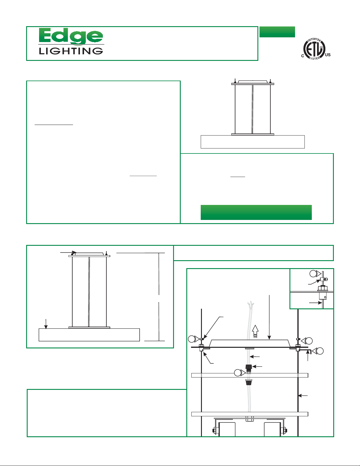
Adjust the Fixture Height
MOUNTING
A
PLATE
GLASS SHADE
2: Loosen the Phillips screw on each of the strain reliefs (Do
Not Remove).
1: Determine the desired fixture height (H), from the bottom of
the glass shade to the top the mounting plate.
B
2
STRAIN
RELIEF
STRAIN RELIEF
BUSHING
4
MOUNTING PLATE
CLEAR CORD
CORD GRIP
STRAIN
RELIEF
AIRCRAFT
CABLE
2
2
3
1.5MM ALLEN
WRENCH
AIRCRAFT
CABLE
3: Loosen the set screws on the strain relief bushings with the
the provided 1.5mm Allen wrench.
4: Loosen the cord grip to adjust the clear cord.
1
Page 2
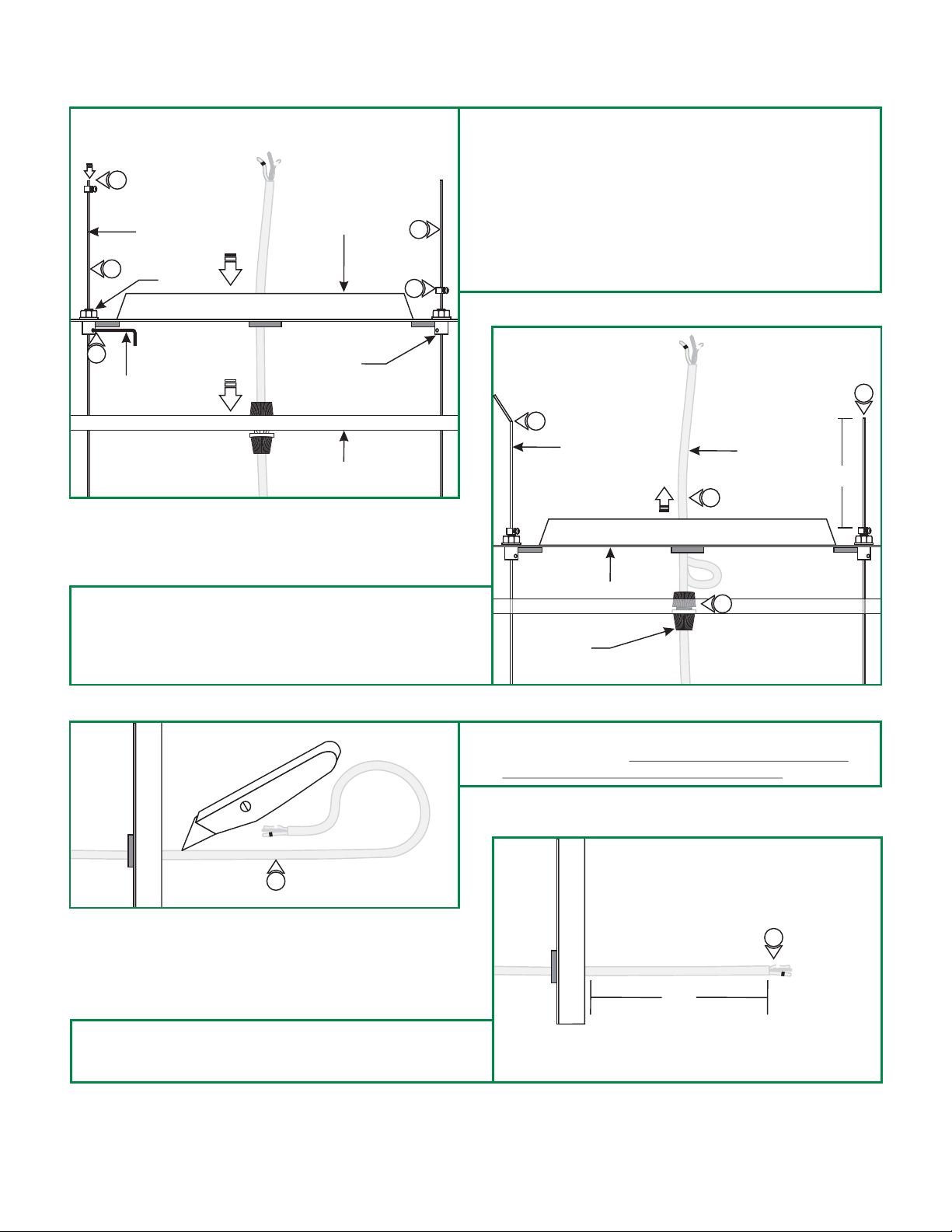
C
7
5
AIRCRAFT
CABLE
NUT
MOUNTING PLATE
5: While holding the aircraft cables slide the mounting plate,
cover and the socket assembly down until the desired height
is achieved.
6: Tighten the set screw on each strain relief bushing with the
1.5mm Allen wrench.
5
7
7: Slide the strain relief down the aircraft cable against the
mounting plate and tighten the Phillips screw. Repeat this
step for the remaining strain reliefs.
6
1.5MM ALLEN
WRENCH
8: Cut the excess aircraft cables off with a sharp cutter (Leave
at least 3" of the cable behind the strain reliefs).
9: Pull the excess clear cord out of the mounting plate and
tighten the cord grip.
STRAIN RELIEF
BUSHING
COVER PLATE
E
D
8
AIRCRAFT
CABLE
MOUNTING PLATE
CORD GRIP
10: From the end of the clear cord, strip the outer insulation
using a sharp knife. Make sure not to nick the inner
wires and trim off the cutout insulation.
CLEAR CORD
3"
9
9
8
10
11: Replace the wires with the black and white tags near the
insulation. Leave 6" of the wire behind the mounting plate
for power connection. Trim off the excess wires.
F
11
6"
2
Page 3

Install the Fixture
G
POWER WIRE
#8-32
SCREW
1
2
3: Make sure the mounting plate and the bare wire is grounded
in accordance with local electrical codes.
4: Connect the clear wire with a white tag to the neutral power
wire with a wire nut.
2
ELECTRICAL
BOX HOLE
MOUNTING
PLATE
NOTE: Make sure the glass shade is detached.
NOTE: Use the provided universal crossbar if the mounting
plate holes do not line up with the electrical box holes.
1: Feed the power wires through the mounting plate center
hole.
2: Secure the mounting plate to the electrical box holes with
the two #8-32 screws provided.
H
3
5
4
5: Connect the clear wire with a black tag to the hot power wire
with a wire nut.
DI
COVER
PLATE
MAGNET
6
6
6
6: Slide the cover plate up against the mounting plate, the
magnets will hold the cover plate in place.
3
Page 4

Install the Lamps and Shade
J
LAMP
1
SOCKET
CAUTION:
lamping, disconnect the power to the fixture.
Use MAX 150 Watt Type T10 Medium Base
Halogen Lamp For Each Socket.
1: Screw each lamp completely into the socket holes.
To reduce risk of a burn or electrical shock during
K
GLASS SHADE
2
GLASS RING
HOLDER
2: Insert the glass ring holder on an angle into the glass shade
center hole and lay the glass shade on the glass ring holder.
L
4
GLASS SHADE
3
HOOK
5: If the glass shade is not leveled horizontally, slide the cover
plate down to expose the mounting plate.
GLASS RING
HOLDER
3
3: To secure the glass shade in place, use the hooks inside the
glass shade and hook them inside of the glass ring holder.
4: Lower the socket assembly into the glass shade.
M
STRAIN
RELIEF
BUSHING
1.5MM ALLEN
WRENCH
CORD GRIP
6: Readjust the uneven aircraft cable by loosening the set
screw on the strain relief bushing with the 1.5mm Allen
wrench. Push the aircraft cable in and re-tighten the set
screw.
7: Slide the cover plate up against the mounting plate.
COVER PLATE
AIRCRAFT
CABLE
CLEAR CORD
4
 Loading...