

Page 1
1718 W. Fullerton Ave
Chicago, IL 60614
Tel: 773-770-1195
Fax: 773-935-5613
www.edgelighting.com
© 2013 Edge Lighting. All Rights Reserved.
info@edgelighting.com
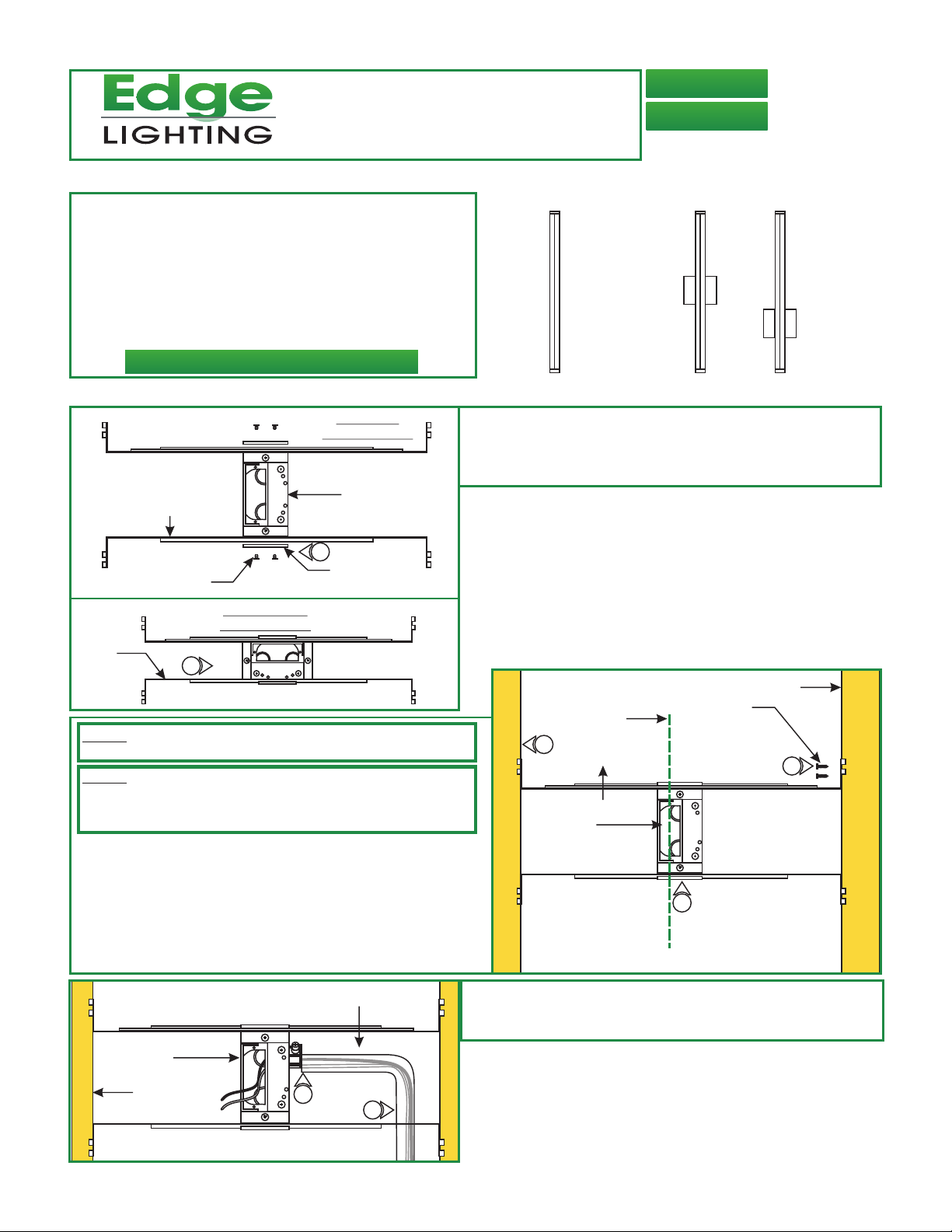
Installation Instructions for Twiggy Square Lens 12 VAC
IMPORTANT INFORMATION
- This instruction shows a typical installation.
- This product is wall mount only.
- This product is dimmable with a low-voltage electronic
dimmer.
- This product must be installed by a qualified electrician.
- The 1RE version mounts to the provided C-1RE-JBOX. The
4SQ version mounts to standard electrical box with plaster
ring or octagon box.
SAVE THESE INSTRUCTIONS!
1RE
Section One: Steps For TW12-1RE Version
A
ADJUSTABLE
MOUNTING BAR
3
2
1
1
2
3
VERTICAL
ORIENTATION
JUNCTION
BOX
1: Determine channel orientation. Mount each adjustable
mounting bar to one side of the junction box and secure
them with the provided mounting brackets and two Phillips
screws.
TW12-S1-1RE-_
TW12-S1-4SQ-_
w/4" SQUARE CANOPY
J-BOX IN
MIDDLE
904-TW12-S1-01
J-BOX
OFFSET
1
PHILLIPS
SCREW
MOUNTING
BRACKET
HORIZONTAL
ORIENTATION
JUNCTION
BOX
1
3
3
2
2
1
1
NOTE: The adjustable mounting bars mount to studs that are spaced
13" to 24" apart.
NOTE: Ensure the opening of the junction box is alinged with the
center of the desired fixture location. If necessary, adjust the junction
box location by loosening the screws and sliding the junction box to
the proper location. Tighten the Phillips screws after adjusting.
Select the location between the two studs for the junction
2:
box to be mounted.
3: Place the adjustable mounting bars between the studs.
4: Make sure the lips on the adjustable mounting bars are
against the studs. Secure the adjustable bars to the studs
with the eight #8 screws.
C
CONDUIT
B
FIXTURE LOCATION
CENTER LINE
#8 SCREW
STUD
3
4
JUNCTION
BOX
3
2
1
1
2
3
2
ADJUSTABLE
MOUNTING BAR
5: Remove a knockout to install the power line conduit.
JUNCTION
BOX
STUD
6: Install the conduit and run the 120V power wires.
3
2
1
1
2
3
5
6
1
Page 2
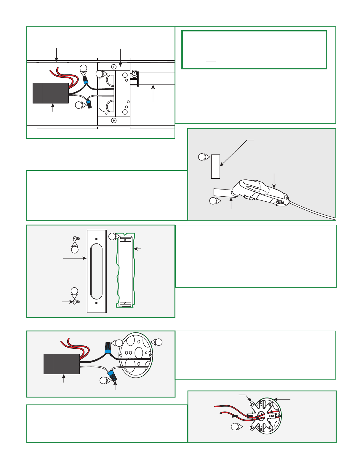
D
ADJUSTABLE
MOUNTING BARS
TRANSFORMER
NOTE: If necessary junction box opening can be adjusted to two
JUNCTION
BOX
8
9
3
2
1
1
2
7
3
CONDUIT
positions: Position 2 at 0.95" (recommended for this installation),
or Position 3 at 1.05". Simply loosen screws and tighten to the
corresponding position labeled on junction box. POSITION ONE
SHOULD NOT BE USED FOR THIS INSTALLATION as it will
not allow access to the LED transformer after installation.
7: Connect the white transformer wire to the neutral power
wire with a wire nut.
8: Connect the black transformer wire to the hot power wire
with a wire nut.
9: Place the transformer and transformer wires inside the
junction box.
Mark a rectangle shape on drywall where the junction box
10:
opening will be located depending on selected position.
11: Cut out the marked rectangle opening, using a "Dremel
Multi-Max" with the "wood & drywall" cutting bit.
12: Install & finish drywall.
F
14
GOOF PLATE
(ONLY USE IF JAGGED
PLASTER EDGE, PAINT
TO MATCH)
14
SCREW
13
JUNCTION BOX
OPENING EDGE
E
10
11
WOOD & DRYWALL
CUTTING BIT
13: Install the drywall and plaster around the junction box
opening. Sand and then paint.
14: If necessary: Use the Goof Plate if the junction box
opening has a lot of imperfection/jagged edges. Install the
provided goof plate (paint to match prior) with the two
screws.
15: Complete installation by following steps in Section Three.
RECTANGLE
OPENING
DREMEL
MULTI-MAX
DRYWALL
Section Two: Steps For TW12-4SQ Version
G
TRANSFORMER
1
WIRE NUT
2
3
1: Connect the white power supply wire to the neutral power
wire with a wire nut.
2: Connect the black power supply wire to the hot power wire
with a wire nut.
3: Place the power supply and wires inside the electrical box.
H
4: Feed the transformer wires from the crossbar center hole
and mount the crossbar to the electrical box holes with the
two #8-32 screws provided.
5: Complete installation by following steps in Section Three.
CROSSBAR
4
ELECTRICAL BOX
#8-32 SCREW
2
Page 3

Section Three: Install Fixture For Both Versions
I
WALL
MARK LOCATION
1
JUNCTION
BOX
CHANNEL
MARK LOCATION
1
NOTE: It is recommended more than one person to assist in
this installation.
NOTE: Fixture can be mounted in a horizontal or vertical
position.
NOTE: The junction box does not need to be in middle of the
channel (could be at either end) but needs to be aligned in the
center of the channel.
1: Align the channel to the junction box opening. Make
markings to each end of the channel and also make a center
line from end to end. Note which side the wires are
located to later install the locking clip to the opposing
side.
NOTE: TW12-S1-1RE shown for demonstration purposes
NOTE: Locking clip must be installed in the opposite direction
of the fixture wire. Fixtures greater than 36" are provided with
two locking clips.
NOTE: The junction box could be offset, but needs to be
aligned to the center of the channel.
2: From the two existing marks, make additional marks by
following drawing H (a typical suggested location with
measurements for the locking clip - longer runs contain two
locking clips) to install the locking & mounting clips properly.
Mounting clips must be installed every 20" from each other.
K
3
CEILING
ANCHOR
4
ANCHOR MUST
BE FLUSH TO WALL
J
LOCKING
CLIP
WALL
NOTE:
if mounting the clips to a wood surface directly.
EXISTING MARK
7 5/8"
6 5/8"
2
JUNCTION
BOX
CENTER LINE
MARK
2
3-3/4"
2-3/4"
EXISTING MARK
Steps 3 and 4 are for drywall mounting. Omit these steps
MOUNTING
CLIP
20" TYP.
3: Tap the anchors onto the marked points up to the threaded
portion with a hammer.
4: Screw in the threaded portion of the anchors with a Phillips
screwdriver.
L
5: Secure the locking clip(s) & mounting clip(s) to the marked
surface or anchors by passing the screws through the clip
holes followed by the washers into the marked points or
anchors. Locking clips mount onto mounting clips.
WALL
LOCKING CLIP
#6 SCREW
WASHER
MARKED
POINT/ANCHOR
5
ELECTRICAL BOX
MOUNTING
CLIP
5
3
Page 4

M
13
13
FIXTURE BODY
CANOPY
#4-40
SCREW
1/16
ALLEN
WRENCH
FIXTURE
BODY
LOCKING CLIP
6: Connect each power supply wire to a fixture body wire with
a wire nut.
7: Place the wires and wire nut connection inside the junction
box.
6
JUNCTION BOX
WALL
8: Carefully snap fixture body onto the locking & mounting
clip(s) then slide into receiving bracket to lock in place.
Make sure not to nick the wires.
NOTE: If the receiving bracket interferes with the electrical box,
then relocate the bracket by loosening the set screws and make
the necessary adjustments.
O
N
RECEIVING BRACKET
BACK VIEW
FIXTURE
BODY
8
LOCKING CLIP
JUNCTION BOX
8
8
MOUNTING CLIP
LOCKING CLIP
WALL
13 (OPTIONAL): For 4" Square Canopy installations, place
each canopy piece against the crossbar and secure it to the
electrical box holes with the provided #4-40 screws using the
1/16 Allen wrench.
WALL
GENERAL WIRING DIAGRAM
INPUT
120VAC
WHITE (NEUTRAL)
BLACK (HOT)
ELECTRONIC LOW
VOLTAGE DIMMER
YELLOW
WHITE (NEUTRAL)
BLACK (HOT)
LED TRANSFORMER
AUDREY CHANNEL
RED (12VAC)
RED (12VAC)
4
 Loading...