

Page 1
904-TWH12-D1-01
2
3
1
2
3
1
2
3
1
2
3
1
2
3
1
2
3
1
2
3
1
2
3
1
© 2014 Edge Lighting. All Rights Reserved.
1718 W. Fullerton Ave
Chicago, IL 60614
Tel: 773-770-1195
Fax: 773-935-5613
www.edgelighting.com
info@edgelighting.com
TWH12-D1-1RE-_
TWH12-D1-4SQ-_
Installation Instructions for Twiggy Hinged 12V AC, Direct Lens with 4"
Square Canopy or 1" Rectangular Canopy
IMPORTANT INFORMATION
- This instruction shows a typical installation.
- This product must be installed by a qualified electrician.
- The 1RE version mounts to the provided C-1RE-JBOX. The
4SQ version mounts to standard electrical box with plaster
ring or octagon box.
- Before beginning any electrical work, ensure that
the power to the installation is turned OFF!
SAVE THESE INSTRUCTIONS!
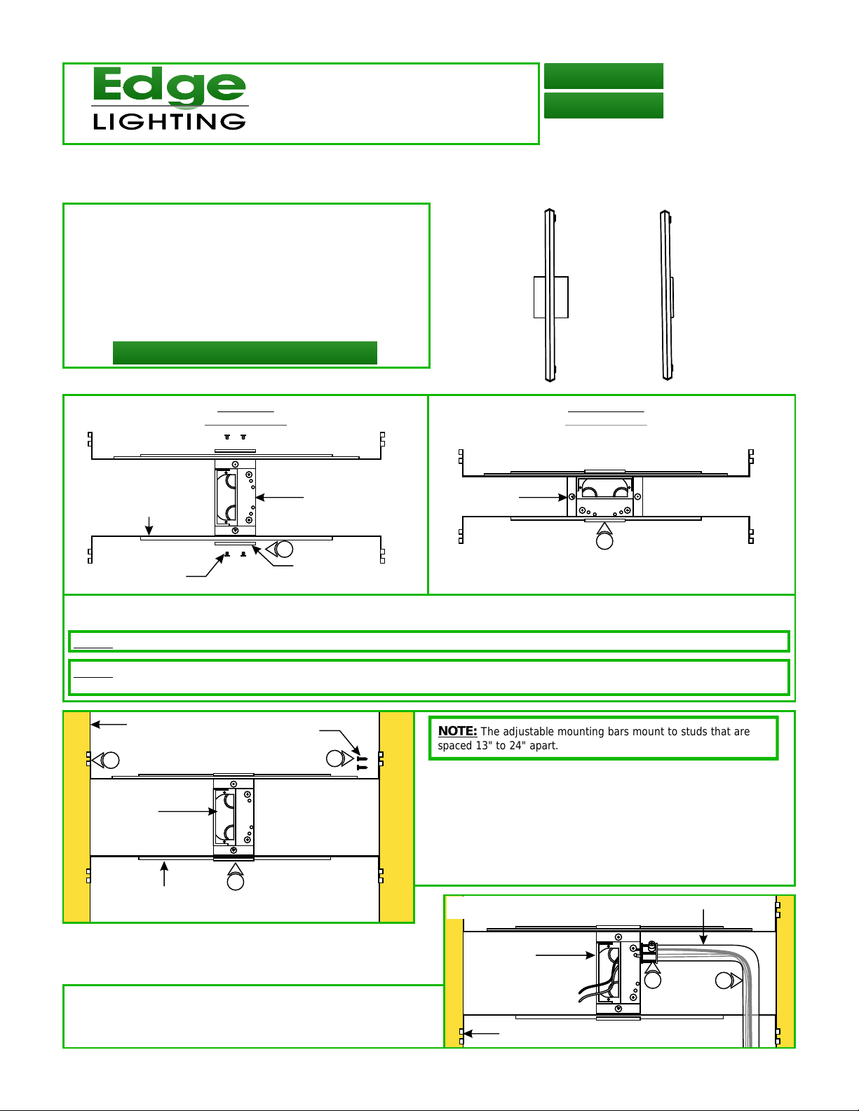
Section One: Steps for TWH12-D1-1RE
A
VERTICAL
ORIENTATION
HORIZONTAL
ORIENTATION
ADJUSTABLE
MOUNTING BAR
PHILLIPS
SCREW
JUNCTION
BOX
1
MOUNTING
BRACKET
JUNCTION
BOX
1
1: Mount each adjustable mounting bar to one side of the junction box (mounts to any side of the housing depending on the
orientation of the channel) and secure them with the mounting brackets and two Phillips screws provided.
NOTE: The adjustable mounting bars mount to studs that are spaced 13" to 24" apart.
NOTE: Ensure the opening of the junction box is alinged with the center of the desired fixture location. If necessary, adjust the junction box
location by loosening the screws and sliding the junction box to the proper location. Tighten the Phillips screws after adjusting.
B
STUD
#8 SCREW
NOTE: The adjustable mounting bars mount to studs that are
spaced 13" to 24" apart.
3
4
Select the location between the two studs for the junction
2:
box to be mounted.
JUNCTION
BOX
3: Place the adjustable mounting bars between the studs.
4: Make sure the lips on the adjustable mounting bars are
against the studs. Secure the adjustable bars to the studs
with the eight #8 screws.
C
CONDUIT
ADJUSTABLE
MOUNTING BAR
2
5: Remove a knockout to install the power line conduit.
6: Ensuring power to the junction box is off, install the conduit
and run the 120V power wires.
JUNCTION
BOX
STUD
5
6
1
Page 2
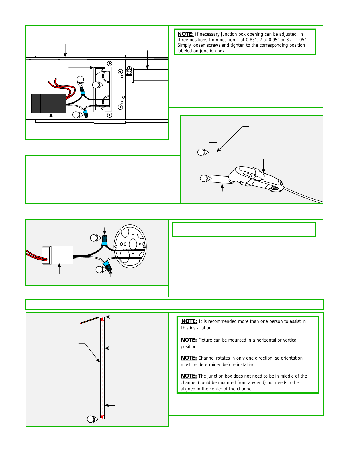
D
2
3
1
2
3
1
TRANSFORMER
ADJUSTABLE
MOUNTING BARS
JUNCTION
BOX
8
7
NOTE: If necessary junction box opening can be adjusted, in
three positions from position 1 at 0.85", 2 at 0.95" or 3 at 1.05".
CONDUIT
9
Simply loosen screws and tighten to the corresponding position
labeled on junction box.
7: Connect the white transformer wire to the neutral power
wire with a wire nut.
8: Connect the black transformer wire to the hot power wire
with a wire nut.
9: Place the transformer and transformer wires inside the
junction box.
E
RECTANGLE
OPENING
DRYWALL
10
Mark a rectangle shape on drywall where the junction box
10:
opening will be located depending on selected position.
11: Cut out the marked rectangle opening, using a "Dremel
Multi-Max" with the "wood & drywall" cutting bit.
12: Follow steps in Section Three to complete installation.
11
Section Two: Steps for TWH12-D1-4SQ
D
TRANSFORMER
Section Three: Install Fixture
NOTE: Twiggy Hinge w/rectangular junction box shown for illustration purposes.
WIRE NUT
2
1
WIRE NUT
NOTE: Low-voltage power wires should be present in the
junction box before completing the steps in this section.
1: Connect the white power supply wire to the neutral power
wire with a wire nut.
2: Connect the black power supply wire to the hot power wire
with a wire nut.
3: Place the power supply and wires inside the electrical box.
4: Follow steps in Section Three to complete installation.
DREMEL
MULTI-MAX
WOOD & DRYWALL
CUTTING BIT
F
WALL
1RE JUNCTION
BOX OPENING
MARK LOCATION
CENTER LINE
CHANNEL
1
NOTE: It is recommended more than one person to assist in
this installation.
NOTE: Fixture can be mounted in a horizontal or vertical
position.
NOTE: Channel rotates in only one direction, so orientation
must be determined before installing.
NOTE: The junction box does not need to be in middle of the
channel (could be mounted from any end) but needs to be
aligned in the center of the channel.
1: Center the channel to the junction box opening. Make
markings to each end of the channel and also make a center
line from end to end.
Page 3

HINGE
BACK OF CHANNEL
MOUNTING
HOLE
G
5
HINGE
CHANNEL
If the junction box is located at one end of the channel, then
NOTE:
loosen the #4-40 set screw with the 0.05 Allen wrench on one of the
back cover moving the opening hole to one end. Pull the wire out of
that end & retighten the #4-40 set screw with the 0.05 Allen wrench.
HINGE LINE (3/16" AWAY
FROM THE CENTER LINE)
2
CENTER LINE
2
HINGE
WALL
2: Unfold the channel hinges. Align the channel between the
marked lines and mark the hinge holes 3/16" away from the
center line.
E
#4-40
SET SCREW
CHANNEL
0.05 ALLEN
WRENCH
BACK COVER
WALL
H
3
CEILING
ANCHOR
4
ANCHOR MUST
BE FLUSH TO WALL
5: Line up the hinge to the anchors and secure it by tightening
the #8 screws to each hinge.
3: Tap the anchors onto the marked points up to the threaded
portion with a hammer.
4: Screw in the threaded portion of the anchors with a Phillips
screwdriver.
J
CHANNEL
HINGE
5
#8 SCREW
5
WALL
2
Page 4

INSULATION
BRAIDED
WIRE
INNER
INSULATION
BARE WIRE
1/8"
COAXIAL CABLE
1/4"
INSULATION
BRAIDED
WIRE
COAXIAL CABLE
1"
K
JUNCTION BOX
CHANNEL
7: Using the 16 AWG hole of a pair of wire strippers, remove 1"
of outer plastic insulation from the coaxial cable.
COVER
6
COAXIAL
CABLE
6: Pull the coaxial cable through center hole of junction box
cover.
L
7
WIRE STRIPPERS
M
8
COAXIAL
CABLE
WIRE STRIPPERS
9
10: Unscrew the coaxial connector covers and remove from the
connector assembly.
O
2MM ALLEN
WRENCH
M4 SET
SCREW
12
M3 SET
SCREW
1.5MM ALLEN WRENCH
11
8: Using the 18 AWG hole of the wire strippers, remove
braided wire leaving 1/4" from the outer plastic insulation.
9: Using the 20 AWG hole of the wire strippers, remove 1/8"
of inner plastic insulation from the end of the coaxial cable.
N
COAXIAL
CONNECTOR
COVER
10
CONNECTOR
ASSEMBLY
COAXIAL
CONNECTOR
COVER
11: Using the provided 1.5mm Allen Wrench, remove the M3
set screw from the coaxial connector assembly.
12: Using the provided 2mm Allen wrench to loosen (do not
remove) the M4 set screw.
13: Slide the connector cover over the coaxial cable.
14: Place the ferrule over the braided wire of the coaxial cable.
P
COAXIAL
CONNECTOR
COVER
13
BRAIDED
WIRE
FERRULE
14
3
Page 5

2
3
1
2
3
1
Q
COAXIAL
COAXIAL
CABLE
CONNECTOR
ASSEMBLY
15
15: Insert the coaxial cable into the coaxial connector until the wires of the center conductor are visible through the M3 set
screw hole.
NOTE: Ensure that the split in the ferrule is aligned 90° from the M4 set screw (see inset).
CABLE
CONNECTOR
ASSEMBLY
FERRULE
R
COAXIAL
CABLE
1.5MM ALLEN
WRENCH
CONNECTOR
ASSEMBLY
16
M3 SET
SCREW
17: Use the provided 2mm Allen wrench to securely tighten the
M4 set screw until it squeezes the wire ferrule tightly to the
coaxial cable.
T
COAXIAL
18
CONNECTOR
COVER
16: Use the provided 1.5mm Allen wrench to replace and
securely tighten the M3 set screw.
S
2MM ALLEN
WRENCH
COAXIAL
CABLE
17
M4 SET
SCREW
CONNECTOR
ASSEMBLY
18: Replace the coaxial connector cover and tighten into
place.
COAXIAL
CABLE
19: Connect the red wire from the coaxial connector to one of
the LED driver wires using a wire nut.
20: Connect the black wire to the remaining LED driver wire
using a wire nut.
21: Place all connections into the junction box.
U
COAXIAL
CONNECTOR
WIRE
NUT
WIRE
NUT
19
20
4
Page 6

ROTATES UP TO 90º
HINGE
BACK OF CHANNEL
TIGHTEN SET
SCREW TO
HOLD
POSITION
V
22
CHANNEL
JUNCTION
BOX
22: Attach the junction box cover to the junction box with the
provided hex screw.
HEX SCREW
COVER
23: If necessary channel can be rotated up to 90º degrees, and
to hold the position, tighten the M2 set screw to each the
hinge with a 0.9mm Allen wrench.
GENERAL WIRING DIAGRAM
INPUT
120VAC
WHITE (NEUTRAL)
BLACK (HOT)
ELECTRONIC LOW
VOLTAGE DIMMER
YELLOW
WHITE (NEUTRAL)
BLACK (HOT)
LED TRANSFORMER
W
RED (12VAC)
RED (12VAC)
COAXIAL
CONNECTOR
23
TWIGGY
COAXIAL
CABLE
5
 Loading...