

Page 1
Installation Instructions For
© 2014 Pure Lighting. All Rights Reserved.
IMPORTANT INFORMATION
- This fixture is wall or ceiling mount.
- This instruction shows a typical installation.
- Consult the configuration notes on Page 1 before
beginning any installation.
- This product is ETL listed for indoor use.
SAVE THESE INSTRUCTIONS!
TruLine .5A 24VDC
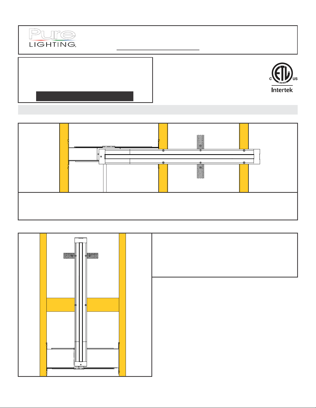
Section One: Basic Configuration Options
Horizontal Configuration
INS# 902-TL.5A-01
1718 W. Fullerton Ave
Chicago, IL 60614
Tel: 773-770-1195
Fax: 773-935-5613
www.purelighting.com
info@purelighting.com
Horizontal installations are linear runs of channel beginning and ending at an end cap and junction/take-up box on a single plane
surface. Runs can be up to 40' in length and the LED strip lays in the bottom of the channel.
Horizontal installations are typically installed perpendicular to wall studs or ceiling joists. Where no stud/joist is present (or in a
remodel installation) a mounting strap may be used to secure the channel to the drywall.
Vertical Configuration
Vertical installations are linear runs of channel beginning and
ending at an end cap and junction/take-up box on a single plane
surface. Runs can be up to 40' in length and the LED strip lays in
the bottom of the channel.
Horizontal installations are typically installed between wall studs
or ceiling joists. Cross-braced stud sections or mounting straps
are suggested to provide additional support every 32".
1
Page 2
Room-Wrapping Configuration
LENS
PLASTER
MOUNTING
STRAP
CHANNEL
DRYWALL
DRYWALL
SCREW
LED
STRIP
Zig Zag Configuration
Room-wrapping configurations are used
for installations that join runs of TruLine
.5A on multiple planes (like a ceiling and a
wall) using miter-cut linear sections of
channel.
For room-wrapping installations, the LED
strip will be installed in the bottom of the
channel.
Zig Zag configurations are used for
installations that join runs of TruLine .5A on a
single plane (like a ceiling or a wall) using
sections of channel joined by L connections.
MOUNTING
STRAP
CHANNEL
DRYWALL
LED
STRIP
PLASTER
LENS
DRYWALL
SCREW
For Zig Zag installations, the LED strip will be
installed in the side of the channel to allow the
strip to follow the channel corners.
Section Two: Standard Horizontal Installation
A
ADJUSTABLE
JUNCTION
BOX
PHILLIPS
SCREW
1: Mount each adjustable mounting bar to one side of the
junction box and secure them with the mounting brackets
and two Phillips screws provided.
1
MOUNTING BAR
INSTALLATION
DIRECTION
MOUNTING
BRACKET
B
NOTE: The adjustable mounting bars mount to studs that
are spaced 13" to 24" apart.
2: Place the lips on the adjustable mounting bars against
the studs. Secure the adjustable bars to the studs with
the eight #8 screws.
3: Install conduit (if required by local electrial code) and run
low-voltage power wires to the junction box.
2
ADJUSTABLE
STUD
MOUNTING BAR
3
CONDUIT W/
LOW-VOLTAGE WIRES
#8 SCREW
JUNCTION
BOX
2
Page 3
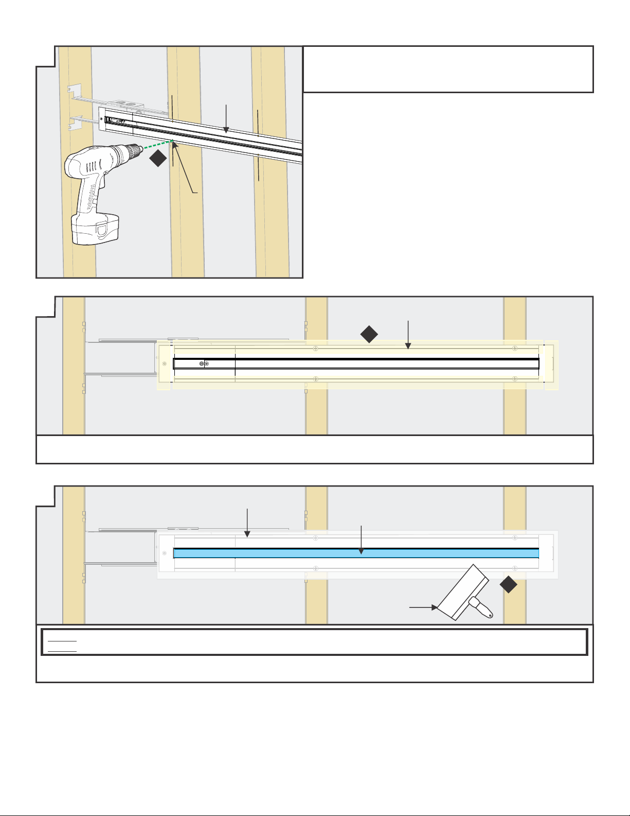
C
6" FIXED
JAB SAW
4
4: Cut a section of drywall using a 6" fixed jab saw or other
appropriate tool to expose the mounting plate area.
D
6
STUD
0.75"
5: Determine the desired length of lit installation area and mark on wall. The total installation length cut will need to be 1 3/4" longer
than the desired lit installation area to account for the fixture end caps. (For example, a desired 48" lit area will require a
drywall cut of 49 3/4" inches). Mark this length on the wall using the junction box mounting plate and a level as a guide.
6: Cut out the marked area using a "Dremel Multi-Max" or a 6" Fixed Jab Saw.
7: Mark the location of the studs to the drywall for future reference.
NOTE: To install channel in a wall without standard-spaced studs, install perforated mounting straps every 32" behind drywall
and secure using two drywall screws. Mark the location of any mounting straps to the drywall.
E
JUNCTION BOX
8
9
7
MARKING
DESIRED LIT LENGTH
5
8: Connect the red power supply (24VDC+) wire to the red
power connector wires with a wire nut.
9: Connect the black power supply (24VDC-) wire to the black
power connector wires with a wire nut.
10: Place the wire nut connections inside junction box.
MOUNTING
STRAP
6
1.05"
1.0"
F
11
TRAP DOOR
FRAME
JOINER
BAR
11: Insert the joiner bars halfway into the channel trap door
frame. Tighten the two #4-40 set screws on each joiner bar
with a 0.05" Allen wrench.
12: Slide the other section of channel onto the joining bars and
tighten the remaining #4-40 set screws with a 0.05" Allen
wrench.
12
G
LENS
13
CHANNEL
TRAP DOOR
FRAME
13: Snap the lens into the assembled trap door frame and
channel BEFORE cutting to length. This ensures a proper
fit after installation.
3
Page 4
H
TRAP DOOR
FRAME
CHANNEL
SECTION
LENS
DESIRED LIT LENGTH
14: Cut the assembled trap door frame, channel, and lens to match the desired lit installation length.
I
END CAP
INSERT
15: Place the power connector into the end cap insert.
16: Slide the assembled end cap insert and power connector into
the end cap.
16
15
END CAP
POWER
CONNECTOR
J K
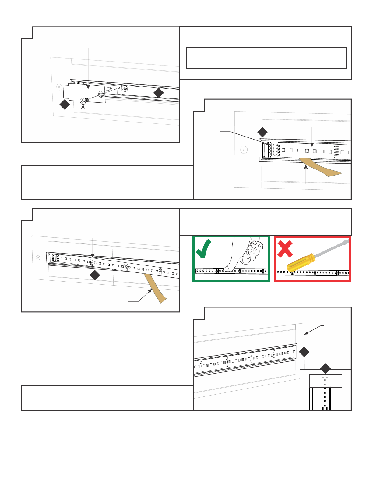
#4-40
SCREW
14
18
17
17: Secure the assembled power connector end cap to the
junction box with the #4-40 screw using a 1.5mm Allen
wrench.
L
19
20
TAKE-UP
BOX
M4 SET
SCREW
CHANNEL
18: Slide the take-up box onto the non-power channel end and
tighten the M4 set screws.
19: Place the assembled channel to the cutout area on the wall
making sure to fully seat it against the power connector end
cap.
20: Attach the assembled trap door frame and channel to the
junction box using the #4-40 screw.
#4-40
SCREW
TRAP DOOR
FRAME
4
Page 5
M
21: Drill and countersink the channel at stud markings.
22: Properly secure the channel to the wall using drywall screws.
Ensure all screw heads are flush with the channel surface.
CHANNEL
21
DRILL AND
COUNTERSINK
N
23: Apply ultra-thin drywall tape along edges of channel to prevent cracking of plaster after installation. DO NOT overlap strips of
drywall tape.
O
PLASTER
CONTRACTOR'S
TAPE
ULTRA-THIN
DRYWALL TAPE
23
24
12" COMPOUND
KNIFE
NOTE: Test the LED strip before any plaster work is done
NOTE: Cover the channel opening with contractor’s tape before plastering.
24: Use a 12" compound knife for a smooth compound spread. Sand, paint, and finish the plaster and drywall before removing the
blue contractor's tape.
5
Page 6
P
TRAP DOOR
26: Remove the blue contractor’s tape from the inside of the
channel. Clean the channel surface with alcohol to remove
any dust or debris before continuing.
IMPORTANT: Soft strip may not properly adhere to channel
surface unless the channel is cleaned with alcohol prior to
application.
27: Attach the trap door to the junction box using the #6-32 screw.
26
27
#6-32
SCREW
28: Carefully remove the backing from the LED soft strip, making
sure not to remove the tape from the soft strip. Line up the red
wire side of the power connector with the “+24VDC” marking
on the Soft Strip. Push the male connector of the Soft Strip
into the female power connector.
R
LED STRIP
29
Q
POWER
CONNECTION
29: Firmly press down the adhesive portion of the soft strip onto
the channel surface while removing the rest of the backing,
making sure there are no air bubbles that can cause surface
irregularities.
28
LED STRIP
PAPER
BACKING
PAPER
BACKING
30: If required, trim the soft strip on the dashed cuttable section,
place the excess soft strip inside the take up box (see inset).
Ensure the entire length of the channel is covered with Soft
Strip to avoid unlit areas.
S
TAKE-UP
BOX
30
30
6
Page 7

T
31
31
CORRECT
31: Snap the lens back onto the channel. Ensure lens is fully seated.
Section Three: Vertical Installation
U
ADJUSTABLE
MOUNTING BAR
PHILLIPS
SCREW
1: Mount each adjustable mounting bar to one side of the
junction box and secure them with the mounting brackets
and two Phillips screws provided.
VERTICAL
ORIENTATION
INSTALLATION
DIRECTION
JUNCTION
BOX
1
MOUNTING
BRACKET
NOT INSTALLED
CORRECTLY
V
STUD
CONDUIT
3
2: Remove a knockout to install the power line conduit (if
required by local electrical code.
3: Install the conduit and run the low voltage 24V DC power
wires coming from the remote power supply to the
junction box.
JUNCTION
BOX
ADJUSTABLE
MOUNTING BAR
W
DRYWALL
4: Refer to the instruction provided with the power supply
along with the wiring diagram for proper wiring.
4: Cut a section of drywall using a 6" fixed jab saw or other
appropriate tool to expose the mounting plate area.
6" FIXED
JAB SAW
3
7
Page 8

X Y
1.0"
DREMEL
MULTI-MAX
DRYWALL
MOUNTING
STRAP
STUD
5
DESIRED LIT LENGTH
6
JUNCTION
BOX
0.75"
1.05"
5: Determine the desired length of lit installation area and
mark on wall. The total installation length cut will need to
be 1 3/4" taller than the desired lit installation area to
account for the fixture end caps. (For example, a desired
48" lit area will require a drywall cut of 49 3/4" inches)
Mark this length on the wall using the junction box
mounting plate and a level as a guide.
6: Cut out the marked area using a "Dremel Multi-Max" or a
6" Fixed Jab Saw.
6" FIXED
JAB SAW
9
10
JUNCTION
BOX
8: Install mounting straps behind the drywall (suggested
spacing is every 32") by threading a drywall screw into
the perforated material.
9: Place the mounting strap behind the cut drywall and rotate
into place using the drywall screw as a handle.
10: Secure the mounting strap to the drywall using two
drywall screws. Mark the location on the drywall.
DRYWALL
SCREW
10
Complete cutting, mounting,
plastering,painting, and LED strip
installation by following Steps 8
through 31 on Pages 3 through 7.
Z
STUD
11
SUPPORT
BRACE
11
ALTERNATE VERTICAL INSTALLATION OPTION:
11: Install 2x4 support braces (suggested spacing is every
32") before installing and finishing drywall.
Section Four: Room-Wrapping
Configuration
Z1
ASSEMBLED
CUTAWAY VIEW
OUTSIDE CORNER
INSIDE CORNER
INSTALLATION NOTES
Room-wrapping installations use LED strip bent 90° for inside
or outside corner configurations. Channel sections will be
miter cut on-site.
8
Page 9

45°
45°
Z2 Z3
1.0"
DESIRED LIT LENGTH
CEILING
WALL
2
DESIRED LIT LENGTH
1
JUNCTION
0.75"
1: Install junction box and low-voltage power.
2: Measure and mark installation length, allowing for 0.75"
extra space at junction box for power end cap and 1.0" inch
at the end of the installation for the take-up box. Cut
out marked areas using appropriate tools.
BOX
3: Insert the joiner bars halfway into the channel trap door
frame. Tighten the two #4-40 set screws on each joiner bar
with a 0.05" Allen wrench.
4: Slide the other section of channel onto the joining bars and
tighten the remaining #4-40 set screws with a 0.05" Allen
wrench.
TRAP DOOR
FRAME
TRAP DOOR
FRAME
5
3
JOINER
BAR
4
LENS
CHANNEL
Z4
MARK DESIRED LIT LENGTH
ASSEMBLED LENS AND CHANNEL w/TRAP DOOR FRAME
ADDITIONAL CHANNEL AND LENS SECTIONS AS REQUIRED
6: Mark the desired lit length on the assembled channel and lens lengths.
Z5
SIDE VIEW
5: Snap the lens into all channel sections BEFORE cutting to
length. This ensures a proper fit after installation.
6
7: Miter cut each section of assembled channel and lens to
match the corner angle. In a 90° inside corner installation
as shown, each channel section is cut at a 45° angle to
form a complete corner.
ANGLE VIEW
7
7
9
Page 10

Z6 Z7
MOUNTING
STRAP
9
JUNCTION
BOX
8
8: Connect the red power supply (24VDC+) wire to the red
power connector wires with a wire nut.
9: Connect the black power supply (24VDC-) wire to the
black power connector wires with a wire nut.
10: Place the wire nut connections inside junction box.
12
13
JUNCTION
BOX
DRYWALL
SCREW
13
11: Install mounting straps behind the drywall (suggested
spacing is every 32") by threading a drywall screw into
the perforated material.
12: Place the mounting strap behind the cut drywall and
rotate into place using the drywall screw as a handle.
13: Secure the mounting strap to the drywall using two
drywall screws. Mark the location on the drywall.
Z8 Z9
END CAP
INSERT
15
END CAP
POWER
CONNECTOR
14: Place the power connector into the end cap insert.
15: Slide the assembled end cap insert and power connector
into the end cap.
14
16: Secure the assembled power connector end cap to the
junction box with the #4-40 screw.
JUNCTION
BOX
#4-40
SCREW
16
10
Page 11

Z10 Z11
CHANNEL
DRYWALL
SCREWS
23
CONTRACTOR'S
TAPE
24
ULTRA-THIN
DRYWALL TAPE
22: Using the marked locations on the drywall, carefully make
holes in the channel flange using the provided square drill
with counter sink bit.
23: Secure the channel using drywall screws. Ensure all
screws are flush to the channel.
24: Apply ultra-thin drywall tape along edges of channel to
prevent cracking of plaster after installation.
Z12 Z13
CONTRACTOR'S
TAPE
12"
COMPOUND
KNIFE
25
PLASTER
NOTE: Test the LED strip before any plaster work is done.
NOTE: Cover the channel opening with contractor’s tape
before plastering.
TRAP
DOOR
FRAME
26
27
#4-40
SCREW
28
TRAP
DOOR
25: Use a 12" compound knife for a smooth compound spread.
Sand, paint, and finish the plaster and drywall before
removing the contractor’s tape.
26: Remove the blue contractor’s tape from the inside of the
channel. Clean the channel surface with alcohol to remove
any dust or debris before continuing.
IMPORTANT: Soft strip may not properly adhere to channel
surface unless the channel is cleaned with alcohol prior to
application.
27: Attach the trap door frame to the junction box using a #4 40 screw.
28: Attach the trap door to the junction box using a #4-40 screw.
11
Page 12

Z14
LED SOFT
STRIP
31
30
PAPER
BACKING
29: Line up the red wire side of the power connector with the
“+24VDC” marking on the Soft Strip. Push the male connector
of the Soft Strip into the female connector of the power cables.
30: Carefully remove the backing from the LED soft strip, making
sure not to remove the tape from the soft strip.
31: Firmly press down the adhesive portion of the soft strip onto
the channel surface while removing the rest of the backing,
making sure there are no air bubbles that can cause surface
irregularities.
POWER
CONNECTOR
29
Z15 Z16
32
BEND SOFT
STRIP TO
FOLLOW
CORNER
33
34
32: Continue removing the paper backing from the soft strip
and installing along channel, pressing adhesive into
place using ONLY a finger.
33: Bend the soft strip to match the installation corner.
34
TAKE-UP
BOX
34: If required, trim the soft strip on the dashed cutting lines
ONLY. Ensure the entire length of the channel is covered
with Soft Strip to avoid unlit areas. Place any excess soft
strip inside the take-up box.
12
Page 13

Z17
35
CORRECT
35: Snap the lens back onto the channel sections. Ensure lens is fully seated.
Section Five: Zig Zag Installation
Z18
JUNCTION
BOX
PHILLIPS
SCREW
1: Mount each adjustable mounting bar to one side of the
junction box and secure them with the mounting brackets
and two Phillips screws provided.
1
ADJUSTABLE
MOUNTING BAR
INSTALLATION
DIRECTION
MOUNTING
BRACKET
35
NOT INSTALLED
CORRECTLY
Z19
STUD
ADJUSTABLE
MOUNTING BAR
#8 SCREW
JUNCTION
BOX
3
CONDUIT W/
LOW-VOLTAGE WIRES
NOTE: The adjustable mounting bars mount to studs that
are spaced 13" to 24" apart.
2: Place the lips on the adjustable mounting bars against
the studs. Secure the adjustable bars to the studs with
the eight #8 screws.
2
Z20
6" FIXED
JAB SAW
4
4: Cut a section of drywall using a 6" fixed jab saw or other
appropriate tool to expose the mounting plate area.
3: Install conduit (if required by local electrial code) and run
low-voltage power wires to the junction box.
Z21
5
TRAP DOOR
FRAME
JOINER
BAR
6
5: Insert the joiner bars halfway into the channel trap door
frame. Tighten the two #4-40 set screws on each joiner bar
with a 0.05" Allen wrench.
6: Slide the other section of channel onto the joining bars and
tighten the remaining #4-40 set screws with a 0.05" Allen
wrench.
13
Page 14

45°
Z22
LENS
7
CHANNEL
TRAP DOOR
FRAME
7: Snap the lens into the assembled trap door frame and
channel BEFORE cutting to length. This ensures a proper
fit after installation.
Z23
LENS
TRAP DOOR
FRAME
DESIRED LIT LENGTH
CHANNEL
SECTION
8: Determine the channel length and cut channel and lens at a 45° angle from the outer corner.
9: Cut additional lens/channel assembly for the opposing 45° angle and any other corners as required for the installation.
Z24
10: Measure and mark installation length, allowing for 0.75"
extra space at junction box for power end cap and 1.0" inch
at the end of the installation for the take-up box. Cut
out marked areas using appropriate tools.
11: Mark the location of the studs to the drywall for future
MARKING
10
reference.
NOTE: To install channel vertically or in a wall without standardspaced studs, install perforated mounting straps every 32"
behind drywall and secure using two drywall screws. Mark the
location of any mounting straps to the drywall.
1.05"
10
1.05"
11
STUD
8
Z25
JUNCTION BOX
12
13
12: Connect the red power supply (24VDC+) wire to the red
power connector wires with a wire nut.
13: Connect the black power supply (24VDC-) wire to the black
power connector wires with a wire nut.
14: Place the wire nut connections inside junction box.
14
Page 15

Z26
TAKE-UP
BOX
15
M4 SET
SCREWS
CHANNEL
15: Slide the take-up box onto the non-power channel end and
tighten the M4 set screws with a 1.5MM Allen wrench.
Z28
90° JOINING
BRACKET
Z27
16
CHANNEL
90° JOINER
BRACKET
16: Insert the 90° joiner bracket halfway into the mitered
channel corner. Tighten the two M4 set screws on each
joiner bar with a 1.5MM Allen wrench.
Z29
19
17
CHANNEL
CHANNEL
17: Slide the other section of mitered channel onto the 90°
joining brackets and tighten the remaining M4 set screws.
Z30
20
#4-40
SCREW
18
18: Rotate the connector and bend power connection wires
to place the power connector into the end cap insert.
19: Slide the assembled end cap insert and power connector
into the end cap.
Z31
#6 SCREW
CHANNEL
TRAP DOOR
21: Using the mark locations on the drywall, carefully make
a hole to channel using the provided square drill with
counter sink bit.
20: Secure the assembled power connector end cap to the
junction box with the #4-40 screw.
22: Secure the channel to the studs/mounting straps through
the drywall with the #6 screws using the provided square
recess bit.
23: Secure the Trap Door frame to the junction box with the
#4-40 screw.
15
Page 16

Z32 Z33
24: Apply ultra-thin drywall tape along edges of channel to
prevent cracking of plaster after installation. DO NOT
overlap strips of drywall tape.
Z34
TRAP DOOR
26
27
#6-32
SCREW
NOTE: Test the LED strip before any plaster work is done.
NOTE: Cover the channel opening with blue contractor’s
tape before plastering.
25: Use a 12" compound knife for a smooth compound spread.
Sand, paint, and finish the plaster and drywall before
removing the blue contractors tape.
26: Remove the blue contractor’s tape from the inside of the
channel. Clean the channel surface with alcohol to remove any
dust or debris before continuing.
IMPORTANT: Soft strip may not properly adhere to channel
surface unless the channel is cleaned with alcohol prior to
application.
27: Attach the trap door to the junction box using a #4-40 screw.
28: Line up the red wire side of the power connector with the
“+24VDC” marking on the Soft Strip. Push the male
connector of the Soft Strip into the female connector of
the power cables.
29: Carefully remove the backing from the LED soft strip, making
sure not to remove the tape from the soft strip. Firmly press
down the adhesive portion of the soft strip onto the channel
surface while removing the rest of the backing, making sure
there are no air bubbles that can cause surface irregularities.
16
Z35
POWER
CONNECTION
28
LED STRIP
PAPER
BACKING
29
Page 17

Z36
30
LED SOFT
STRIP
Z37
31
TAKE-UP
BOX
LED SOFT
STRIP
31
30: Continue applying LED soft strip in the side of channel.
Carefully bend the LED soft strip 90° to match the channel
corner.
Z38
32
CORRECT
32: Snap the lens back onto the channel. Ensure lens is fully seated.
31: If required, trim the soft strip on the dashed cuttable
section, place the excess soft strip inside the take up box
(see inset). Ensure the entire length of the channel is
covered with Soft Strip to avoid unlit areas.
32
NOT INSTALLED
CORRECTLY
17
 Loading...