

Page 1
© 2013 Edge Lighting. All Rights Reserved.
1718 W. Fullerton Ave
Chicago, IL 60614
Tel: 773-770-1195
Fax: 773-935-5613
www.edgelighting.com
info@edgelighting.com
TEB-60L-24DC
904-TEB-60L-24DC-02
Installation Instructions for 24 Volt DC Power Supply
GENERAL INFORMATION
- RISK OF FIRE: This product must be installed by a
qualified electrician. Turn the power to the electrical box off
during installation. Read the "Important Safety Instructions "
before installation.
- This product is not suitable for wet locations. It is approved
for the use at any height above the finished floor.
- A typical installation is shown. Specific installation must be
in accordance with the local electrical codes.
- TO REDUCE RISK OF FIRE, it is important to wire the
power supply for the system as described in this
installation instruction.
SAVE THESE INSTRUCTIONS!
IMPORTANT SAFETY INSTRUCTIONS
- Do not install this power supply in a wet location.
- To reduce the risk of the system overheating and possibly
causing a fire, make sure all the connections are tight.
- Do not install *LED fixture closer than three inches or as
specified in the *LED fixture installation instructions to
curtains or similarly combustible materials. Keep insulation
at least 3" away from the enclosure.
- Turn the electrical power off before modifying the lighting
system in any way.
- The system is "UL" listed for USA and Canada only when
all the products used are supplied by Edge Lighting.
- For dimming options refer to EDGELIGHTING.COM.
* See LED fixture installation instructions for proper
placement.
Install the Power supply
A
1 1
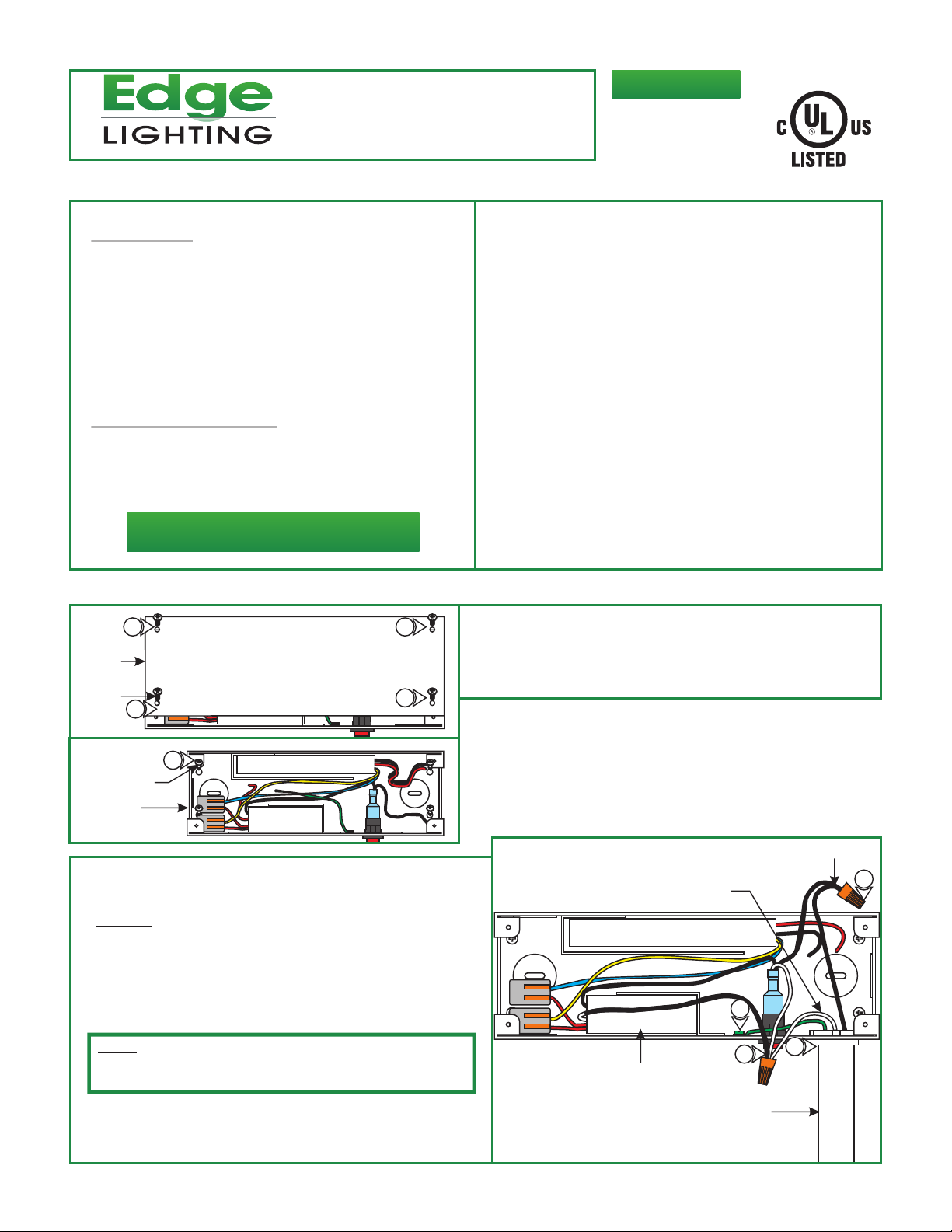
1: Loosen and remove the four Phillips screws on the top of
the power supply to remove the cover.
E360941
COVER
PHILLIPS
SCREW
3: Install a conduit and power wires from the panel to the
power supply.
4: DO NOT connect the power wires to the panel at this time.
5: Ground the power supply housing in accordance with local
electrical codes.
6: Connect the 120 volt hot black wire coming from the power
supply switch to the hot power wire with a wire nut.
7: Connect the 120 volt neutral wire to the white (wraped in
black heat shink) wire coming from the transformer and to
the white wire coming from the power supply switch
(optional) with a wire nut.
1
2
#6 SCREW
POWER
SUPPLY CASE
NOTE: The bottom white wire coming from the switch is for the
switch light. If not using the switch light, cap the wire with a
wire nut.
1
2: Secure the power supply case to the desired location with
the four #6 screws provided.
B
120V NEUTRAL
5
7
TRANSFORMER
CONDUIT
120V HOT
3
6
1
Page 2
C
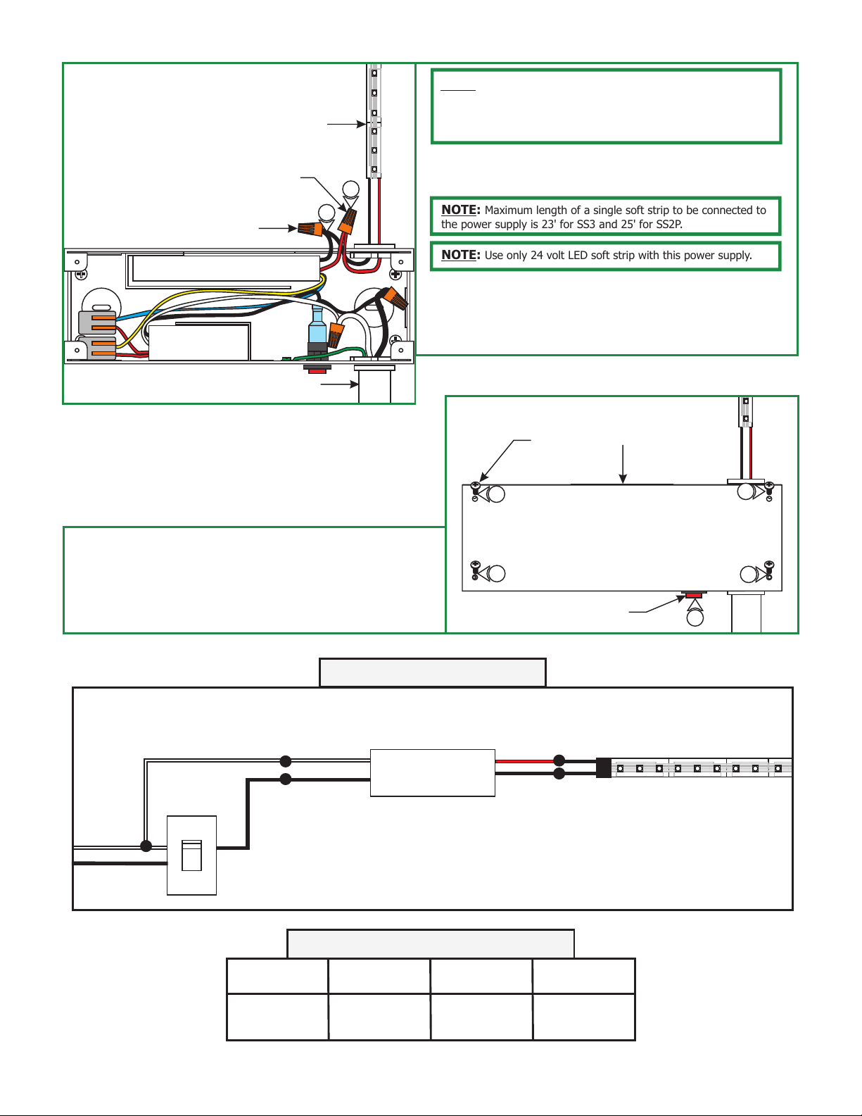
LED SOFT STRIP
24V DC+
24V DC-
CONDUIT
10
NOTE: In order to use small gauge wires from the power
supply to the LED fixture, it is recommended to install the power
supply as near as possible to the LED fixture. See "Low Voltage
Wire Size Chart" below.
8: Use the "Low Voltage Wire Size Chart" below to determine
the proper wire size connecting the power supply wires to
9
the LED soft strip wires.
NOTE: Maximum length of a single soft strip to be connected to
the power supply is 23' for SS3 and 25' for SS2P.
NOTE: Use only 24 volt LED soft strip with this power supply.
9: Connect the red (24V DC+) power supply wire to the red
wire of each LED soft strip with a wire nut.
10: Connect the black (24V DC-) power supply wire to the black
wire of each LED soft strip with a wire nut.
D
PHILLIPS
SCREW
COVER
11: Replace the power supply cover and tighten the four
Phillips screws on top of the cover.
12: Connect the 120 volt power wires at the panel.
13: Turn on the power.
Overall Wiring Diagram
WHITE
BLACK
120V INPUT
NEUTRAL
HOT (OUTPUT)
HOT (INPUT)
ELV
TEB-60L-24DC
11
11
RED
BLACK
SWITCH
11
9
10
11
13
LED SOFT STRIP
24V DC+
24V DC-
LOW VOLTAGE WIRE SIZE CHART
TRANSFORMER
VOLTAGE
24 Volt
WIRE SIZE
UP TO 48 FT
WIRE SIZE
FOR 49-65 FT
WIRE SIZE
FOR 66-107 FT
#14 GA #12 GA #10 GA
2
 Loading...