

Edge Lighting Surface Mount Magnetic Transformer User Manual
© 2012 Edge Lighting. All Rights Reserved.
1718 W. Fullerton Ave
Chicago, IL 60614
Tel: 773-770-1195
Fax: 773-935-5613
www.edgelighting.com
info@edgelighting.com
MT-150-12-P_
PATENT PENDING
904-MT-150-12-P-03
Installation Instructions for Monorail 150
Mount Magnetic Transformer
120 Volt Input to 12 Volt Single
Watt Extended Surface
Feed Output
SAVE THESE INSTRUCTIONS!
P1
GENERAL INFORMATION IMPORTANT SAFETY INSTRUCTIONS
- RISK OF FIRE: This product must be installed by a
qualified electrician. Turn the power to the electrical box off
during installation. Read the "Important Safety Instructions"
before installation.
- This product is suitable only for indoor dry locations and
approved for the use at any height above the finished floor.
- This product contains a magnetic transformer with a built-in
dimming coil.
- Do not install this lighting system in a damp or wet
location.
- Do not conceal or extend bus bar conductor through
building wall.
- To reduce the risk of fire and burns, do not install this
lighting system where the insulated open bus bar
conductors can be shorted or contact any conductive
materials.
- This product may be dimmed only with a low voltage
magnetic dimmer. Using a dimmer other than specified may
work initially, but will eventually cause transformer failure
and void the warranty. The dimmer must be derated as
indicated by the dimmer manufacturer.
- A typical installation is shown. Specific installation must be
in accordance with the local electrical codes.
- Load the circuit of the surface mount transformer to
MAXIMUM 150 Watt.
- To reduce the risk of the system overheating and possibly
causing a fire, make sure all the connections are tight.
- Do not install fixture assemblies closer than six inches, or
as specified in the fixture installation instructions, to
curtains or similarly combustible materials.
- Turn the electrical power off before modifying the lighting
system in any way.
- The fixtures used with the Edge Lighting systems must be
identified for use with the corresponding Edge Lighting
systems.
- Minimum volume of the electrical box must be 6 cubic
inches (98 cubic centimeters).
- The system is "ETL" listed for USA and Canada only when
all the products used are supplied by Edge Lighting.
1
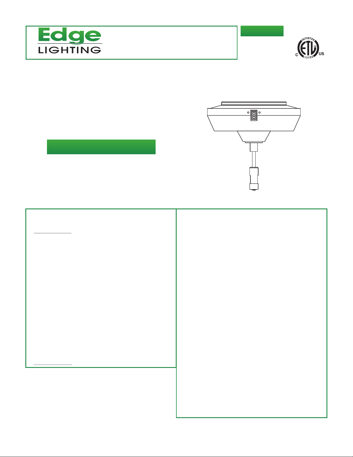
Install the Surface Mount Transformer
A
1
M4 BUTTON
HEAD SCREW
1
2MM ALLEN
WRENCH
1
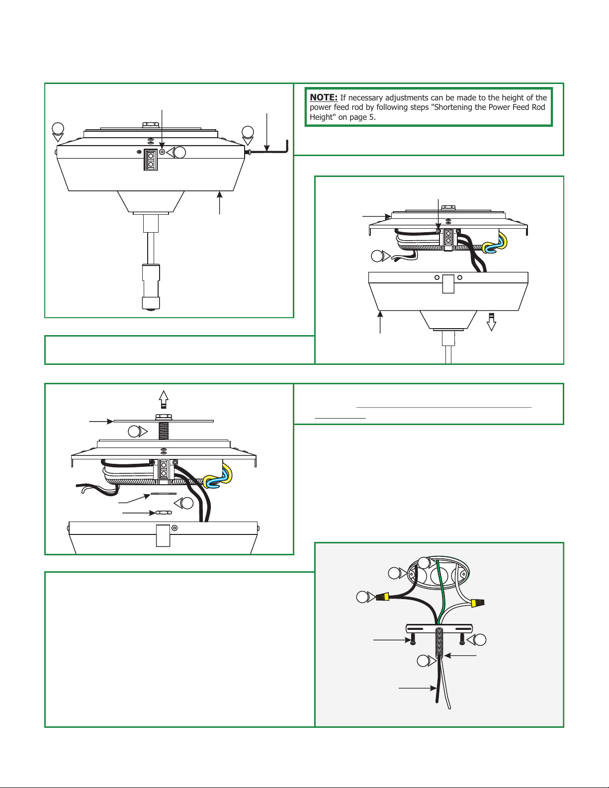
NOTE: If necessary adjustments can be made to the height of the
power feed rod by following steps "Shortening the Power Feed Rod
Height" on page 5.
1: Loosen and remove the five M4 button head screws around
the transformer cover with the provided 2mm Allen wrench.
COVER
P1
2: While holding the transformer, unhook the transformer cover
from the set screw.
C
CROSSBAR
ASSEMBLY
3
B
HOUSING
2
COVER
3: Remove the inside nut and washer to remove the crossbar
assembly. DO NOT DISASSEMBLE THE CROSSBAR
ASSEMBLY.
SET SCREW
P1
WASHER
INSIDE NUT
4: Connect the provided white and black extension wires to the
neutral and hot power wires respectively with the wire nuts
provided.
5: Feed the wires through the crossbar assembly nipple.
6: Place all wires and wire nut connections inside the electrical
box.
7: Mount the crossbar assembly to the electrical box with the
two provided #8-32 screws.
8: Make sure the crossbar assembly is grounded in accordance
with local electrical codes.
3
D
4
#8-32 SCREW
EXTENSION WIRES
8
6
7
5
CROSSBAR ASSEMBLY
NIPPLE
2
 Loading...