

Edge Lighting Sun3C Ceiling LED Downlight Components User Manual
© 2012 Edge Lighting. All Rights Reserved.
1718 W. Fullerton Ave
Chicago, IL 60614
Tel: 773-770-1195
Fax: 773-935-5613
www.edgelighting.com
info@edgelighting.com
SUN3C-_
Installation Instructions for Sun 3 Ceiling LED (Ceiling or Wall)
IMPORTANT INFORMATION
- This product is ETL listed for indoor dry locations.
- This fixture is for wall and ceiling mount only.
SAVE THESE INSTRUCTIONS!
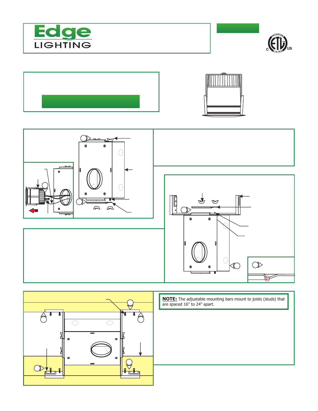
Install the Sun3 Ceiling Housing
904-SUN3C-03
A
TETHER
TERMINAL
TRIM
2
1
2
SCREW
WING
NUT
HOUSING
THREADED
STUD
MOUNTING
BRACKET
3: Mount one adjustable mounting bar to the top of the housing
by sliding it completely under the housing lip.
4: Replace the mounting bracket onto the threaded studs so
that the flange faces the adjustable mounting bar. Tighten
the wing nuts to secure the adjustable mounting bar in
place.
5: Repeat steps 2 through 4 for the bottom of the housing.
1: Carefully pull the trim out of the housing, and remove the
Phillips screw on the tether terminal (safety cable) to release
the trim.
2: Loosen the two top and bottom wing nuts on the housing to
remove the two mounting brackets.
B
WING NUT
3
ADJUSTABLE
MOUNTING BAR
THREADED STUD
HOUSING LIP
5
MOUNTING
BRACKET
4
MOUNTING
BRACKET
FLANGE
C
ADJUSTABLE
MOUNTING
BAR
8
#8 SCREW
8
7
7
STUD
(JOIST)
NOTE: The adjustable mounting bars mount to joists (studs) that
are spaced 16" to 24" apart.
Select the location between the two studs (joist) for the
6:
housing to be mounted.
7: Place the adjustable mounting bars between the studs
(joist).
8: Make sure the lips on the adjustable mounting bars are
against the studs (joist). Secure the adjustable bars to the
8
studs (joist) with the provided eight #8 screws.
1
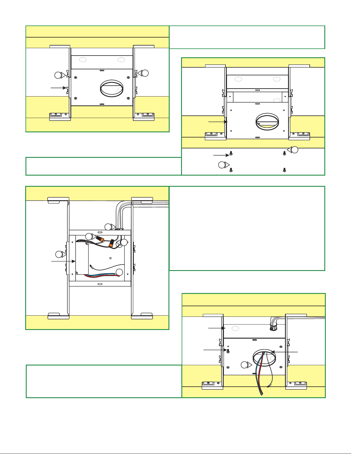
D
WING NUT
9: Slide the housing to desired position. If necessary loosen the
wing nuts to ease the sliding. After the desired position is
achieved tighten all the wing nuts.
E
9
9
COVER
10: Loosen the four #8-32 screws on the front of the housing,
to remove the cover.
F
11
14
15
LED POWER
SUPPLY
13
#8-32
SCREW
10
11: Remove a knock out to install the power line conduit.
12: Install the conduit and run the power line wires to the
housing.
13: Make sure that the housing is grounded in accordance
with local electrical codes.
14: Connect the white LED power supply wire to the neutral
power line wire with a wire nut.
15: Connect the black LED power supply wire to the hot power
line wire with a wire nut.
10
G
16: Feed the black & red output wires from the LED driver
along with the tether through the cover hole. Mount the
cover to the housing with the four #8-32 screws. The hole
should be over the tether and the solid side will
cover the LED driver.
HOUSING
#8-32
SCREW
16
10
COVER
OPENING
2
 Loading...