

Edge Lighting Crystal Spirits User Manual
© 2011 Edge Lighting. All Rights Reserved.
1718 W. Fullerton Ave
Chicago, IL 60614
Tel: 773-770-1195
Fax: 773-935-5613
www.edgelighting.com
info@edgelighting.com
CRYSTALSP-S-_
Installation Instructions for Crystal Spirit Suspension
IMPORTANT INFORMATION
- This product is suitable for indoor locations.
- This product can mount to either a 4" square electrical box
with round plaster ring or an octagon electrical box.
- This product is dimmable with a standard incandescent
dimmer.
SAVE THESE INSTRUCTIONS!
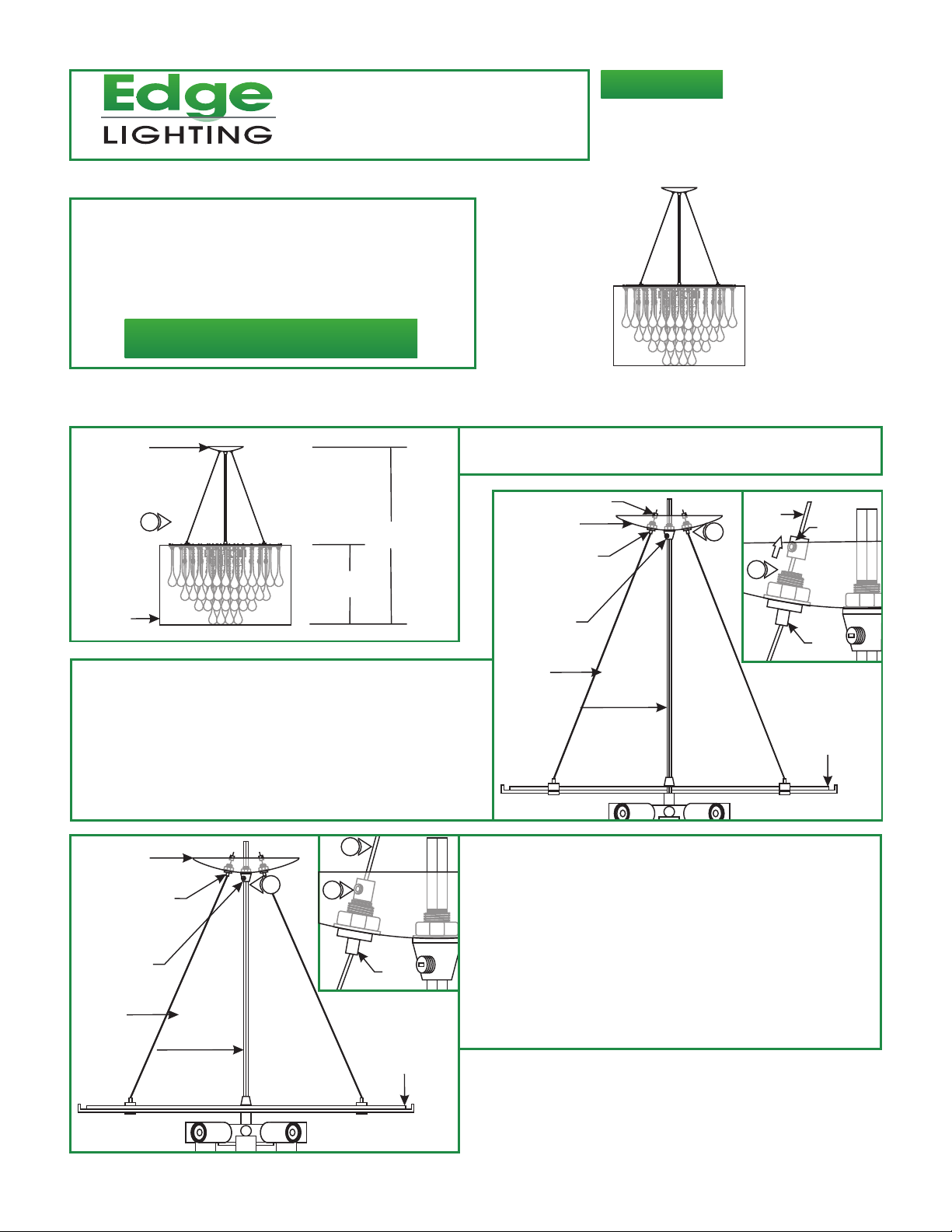
Install the fixture
904-CRYSTALSPIRIT-02
CANOPY
A
1
14.5"
FABRIC
SHADE
H
2: Slide the canopy up and down by pushing the tab on each
aircraft cable grip until desired height is achieved. Release
the tab to lock the aircraft cable in place.
Loosen the M3 set screws on each strain relief with a 1.5mm
3:
Allen wrench.
Slide the strain relief down the aircraft cable behind the cable
4:
grip.
C
CANOPY
9
CABLE GRIP
7
5
1: Determine the desired fixture height (H), from the bottom of
the fabric shade to the top of the canopy.
STRAIN RELIEF
B
CANOPY
CABLE GRIP
CORD GRIP
AIRCRAFT
CABLE
CLEAR CORD
5: T
ighten the set screws on each strain relief.
6:
Repeat steps 4 and 5 for remaining strain reliefs.
2
AIRCRAFT
CABLE
4
M3 SET
SCREW
CABLE
GRIP
SOCKET
PLATE
7: Trim off excess aircraft cable behind the strain reliefs with a
sharp cutter.
CORD GRIP
AIRCRAFT
CABLE
CLEAR CORD
CABLE
GRIP
SOCKET
PLATE
8: Loosen the slotted set screw on the cord grip and push the
excess clear cord into the canopy.
9: Tighten the slotted set screw on the cord grip to lock the
clear cord in place.
1

D
10: Leave 8" of the clear cord exposed behind the canopy for
power connection. Trim off the excess clear cord.
11: From the end of the clear cord, separate the wires from the
cord web for 4" and strip the ends.
11
8"
10
12: Mount the crossbar assembly to the electrical box holes
with the two #8-32 screws provided.
F
CROSSBAR
ASSEMBLY
16
14
15
E
CROSSBAR
ASSEMBLY
12
#8-32 SCREW
NOTE: It is recommended a person to hold the fixture while the
electrician connects the power to the fixture.
13: Make sure the power to the electrical box is off.
14: Make sure that the canopy is grounded in accordance with
local electrical codes.
15: Connect the grooved surface clear wire to the neutral
power wire with a wire nut.
17: Place all wires and wire nut connections inside the canopy.
18: Align and slide the canopy holes onto the threaded studs.
While holding the canopy, tighten the two thumb nuts to
secure the canopy in place.
16: Connect the smooth surface clear wire to the hot power
wire with a wire nut.
G
18
17
CANOPY
THREADED
STUD
18
THUMB NUTS
2
 Loading...