

Page 1
© 2010 Edge Lighting. All Rights Reserved.
1718 W. Fullerton Ave
Chicago, IL 60614
Tel: 773-770-1195
Fax: 773-935-5613
www.edgelighting.com
info@edgelighting.com
CRYSTALSHADOW-S-_
Installation Instructions for Crystal Shadow Suspension
IMPORTANT SAFETY INSTRUCTIONS
To reduce the risk of fire, electrical shock, exposure to
excessive UV radiation, or injury to persons:
- Do not look directly at the lamp while the fixture is on.
- RISK OF FIRE: Use only the type of lamp and maximum
wattage indicated in this instruction manual.
- Never cover the halogen lamp with anything other than a
lamp shield provided by Edge Lighting and never place
flammable material close to the fixture.
- Never turn the fixture on and off by connecting and
disconnecting the halogen lamp.
- Do not touch the fixture head, shade or lamp shield while
the fixture is on. These surfaces may be VERY HOT.
- Do not touch lamp at anytime. Use a soft cloth instead as oil
from skin may damage lamp.
- It is normal for a new halogen lamp to produce minor
smoke when first turned on.
- Do not operate the luminaire with a missing or damaged
shield.
- Turn power off and allow to cool before replacing lamp.
IMPORTANT INFORMATION
- This product is suitable for indoor locations.
- This product can mount to either a 4" square electrical box
with round plaster ring or an octagon electrical box.
- This product is dimmable with a standard incandescent
dimmer.
SAVE THESE INSTRUCTIONS!
904-CRYSTALSHADOW-01
Install the fixture
A
CANOPY
1
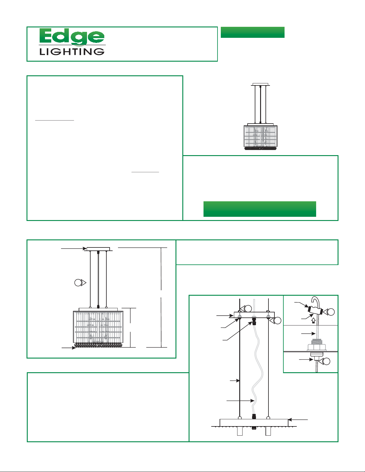
H
12"
CRYSTAL
2: Slide the canopy up and down by pushing the tab on each
aircraft cable grip until desired height is achieved. Release
the tab to lock the aircraft cable in place.
Loosen the slotted set screws on both sides of each strain
3:
relief with a flat head screwdriver.
Pull the end of the aircraft cable out of one strain relief hole.
4:
Slide the strain relief down the aircraft cable behind the cable
grip.
1: Determine the desired fixture height (H), from the bottom of
the crystals to the top of the canopy. The shade height from
top of the socket plate to bottom of the crystals is 12".
2
SET
SCREW
STRAIN
RELIEF
AIRCRAFT
CABLE
CABLE
GRIP
3
2
SOCKET
PLATE
B
4
CANOPY
CABLE GRIP
CORD GRIP
AIRCRAFT CABLE
CLEAR CORD
1
Page 2
C
AIRCRAFT CABLE
CANOPY
5:
AIRCRAFT CABLE
9
STRAIN
RELIEF
7
5
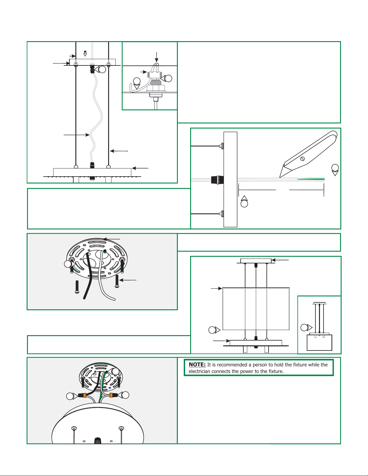
Loop the end of the aircraft cable into the other strain relief
hole and tighten the set screws.
Repeat steps 4 and 5 for remaining strain reliefs.
6:
7: Trim off excess aircraft cable behind the strain reliefs with a
sharp cutter.
8: Loosen the cord grip and push the excess clear cord into the
canopy.
9: Tighten the cord grip to lock the clear cord in place.
CLEAR CORD
AIRCRAFT CABLE
SOCKET
ASSEMBLY
PLATE
10: Leave 8" of the clear cord exposed behind the canopy for
power connection. Trim off the excess clear cord.
11: From the end of the clear cord, strip 4" of the outer
insulation using a sharp knife. Make sure not to nick the
inner wires. Trim off the cut out insulation.
E
12
CROSSBAR ASSEMBLY
#8-32 SCREW
D
8"
10
12: Mount the crossbar assembly to the electrical box holes
with the two #8-32 screws provided.
F
FABRIC
SHADE
CANOPY
11
13: Slide the fabric shade down the fixture and lay it onto the
socket plate.
G
15
17
16
13
SOCKET
PLATE
NOTE: It is recommended a person to hold the fixture while the
electrician connects the power to the fixture.
14: Make sure the power to the electrical box is off.
15: Make sure that the canopy is grounded in accordance with
local electrical codes.
16: Connect the clear wire with a white strip to the neutral
power wire with a wire nut.
17: Connect the other clear wire to the hot power wire with a
wire nut.
13
2
Page 3

H
18
CANOPY
18: Place all wires and wire nut connections inside the canopy.
19: Align and slide the canopy holes onto the threaded studs.
While holding the canopy, tighten the two thumb nuts to
secure the canopy in place.
19
16
CAUTION:
lamping, disconnect the power to the fixture.
NOTE: The G9 lamp has an integral glass envelope and is thus
safe to be used without a lamp shield.
NOTE: Use only fingers and a soft cloth to install the lamps.
Use MAX 50 Watt Type T4, G9 Base, Bi-Pin
Halogen Lamp, For Each Socket.
1: Lift the shade up and lay it crooked onto the socket plate.
For each socket, push the lamp pins completely into the
2:
socket holes.
To reduce risk of a burn or electrical shock during
THREADED STUD
THUMB NUTS
Install the Lamps & Crystals
I
FABRIC
SHADE
1
SOCKET PLATE
2
2
SOCKET
LAMP
J
3
4: Screw the support post onto the threaded nipple in the
middle of the socket plate.
5: Place the glass disk center hole onto the threaded cap
followed by large and small washers.
6: Tighten the threaded cap completely onto the support post
threaded nipple.
SUPPORT POST
THREADED NIPPLE
LARGE SPACER
SMALL SPACER
GLASS DISK
THREADED CAP
3: Remove the threaded cap from the socket glass support post
to remove the glass disk and the washers.
K
FABRIC SHADE
SOCKET PLATE
THREADED NIPPLE
GLASS DISK
SUPPORT
POST
LARGE SPACER
THREADED CAP
4
SMALL SPACER
5
6
3
Page 4

L
SOCKET
ASSEMBLY
HOOP
10
NOTE:
10 to install the crystals in correct position and orientation.
7
7:
Follow step 7 to install all crystals. Follow steps 8 through
To install a crystal, hang the crystal hook into the
designated hoop.
8:
Install each crystal marked "3" into one of the eight hoops
7
HOOK
CRYSTAL
patterned as a square in the center of the socket plate.
9:
Install each crystal marked "2" into one of the eight hoops
patterned as a circle in the middle of the socket plate.
10: Install each crystal marked "1" into one of the twenty five
CRYSTAL 1 : 25pc
hoops patterned as a circle near the edge of the socket
plate.
CRYSTAL 2 : 8pc
9
8
SOCKET
CRYSTAL 3 : 8pc
SOCKET PLATE
11: Carefully lower the fabric shade to rest onto the socket
plate.
SOCKET PLATE : HOOP PATTERN
CRYSTAL 3 : 8pc
CRYSTAL 2 : 8pc
CRYSTAL 1 : 25pc
Carefully lift the glass shade up to expose the socket.
1:
2:
Reach the burnt lamp through the crystals.
3: .
Remove the burnt lamp
4:
Push the new lamp pins completely into the socket holes.
CRYSTAL NAME:QUANTITY
5: Carefully lower the fabric shade to rest onto the socket
assembly.
Replacing the Lamp
M
1
SOCKET
3
FABRIC SHADE
SOCKET PLATE
LAMP
5
4
 Loading...