

Page 1
904-CRYGA-01
© 2014 Edge Lighting. All Rights Reserved.
1718 W. Fullerton Ave
Chicago, IL 60614
Tel: 773-770-1195
Fax: 773-935-5613
www.edgelighting.com
info@edgelighting.com
CRYGA__-12-__SN
CRYGA__-12-__-DL-SN
Installation Instructions for Crystal Galaxy Suspension
and Crystal Galaxy Suspension with Downlight
SAVE THESE INSTRUCTIONS!
GENERAL INFORMATION IMPORTANT SAFETY INSTRUCTIONS
- This product is ETL listed for indoor dry locations and
approved to be used at any height above the finished
floor.
- Do not install fixture assemblies closer than six inches, or
as specified in the fixture installation instructions, to
curtains or similarly combustible materials.
- This product is suitable only for indoor dry locations and
approved for the use at any height above the finished floor.
- This product contains a magnetic transformer with a built-in
dimming coil.
- This product may be dimmed only with a low voltage
magnetic dimmer. Using a dimmer other than specified may
work initially, but will eventually cause transformer failure
and void the warranty. The dimmer must be derated as
indicated by the dimmer manufacturer.
- Load the circuit of the surface mount transformer to
rated capacity only.
- Ensure that power to the junction box is OFF before
beginning any electrical work.
- RISK OF FIRE: This product must be installed by a
qualified electrician. Turn the power to the electrical box
off during installation.
- RISK OF FIRE: Use only the type of lamp and maximum
wattage indicated in this instruction manual.
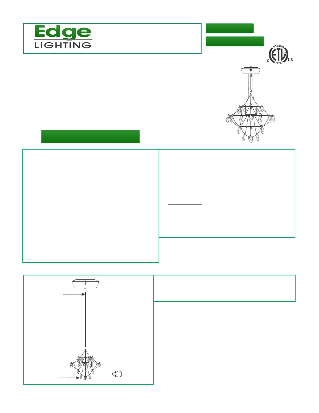
Determine and Adjust Fixture Height
A
SUSPENSION
CABLE
H
1: Push the suspension cable into the center mounting standoff
to determine the desired height from the mounting surface
of the power supply to the bottom of the fixture. Refer to
Figure H for more details.
CRYSTAL
1
1
Page 2
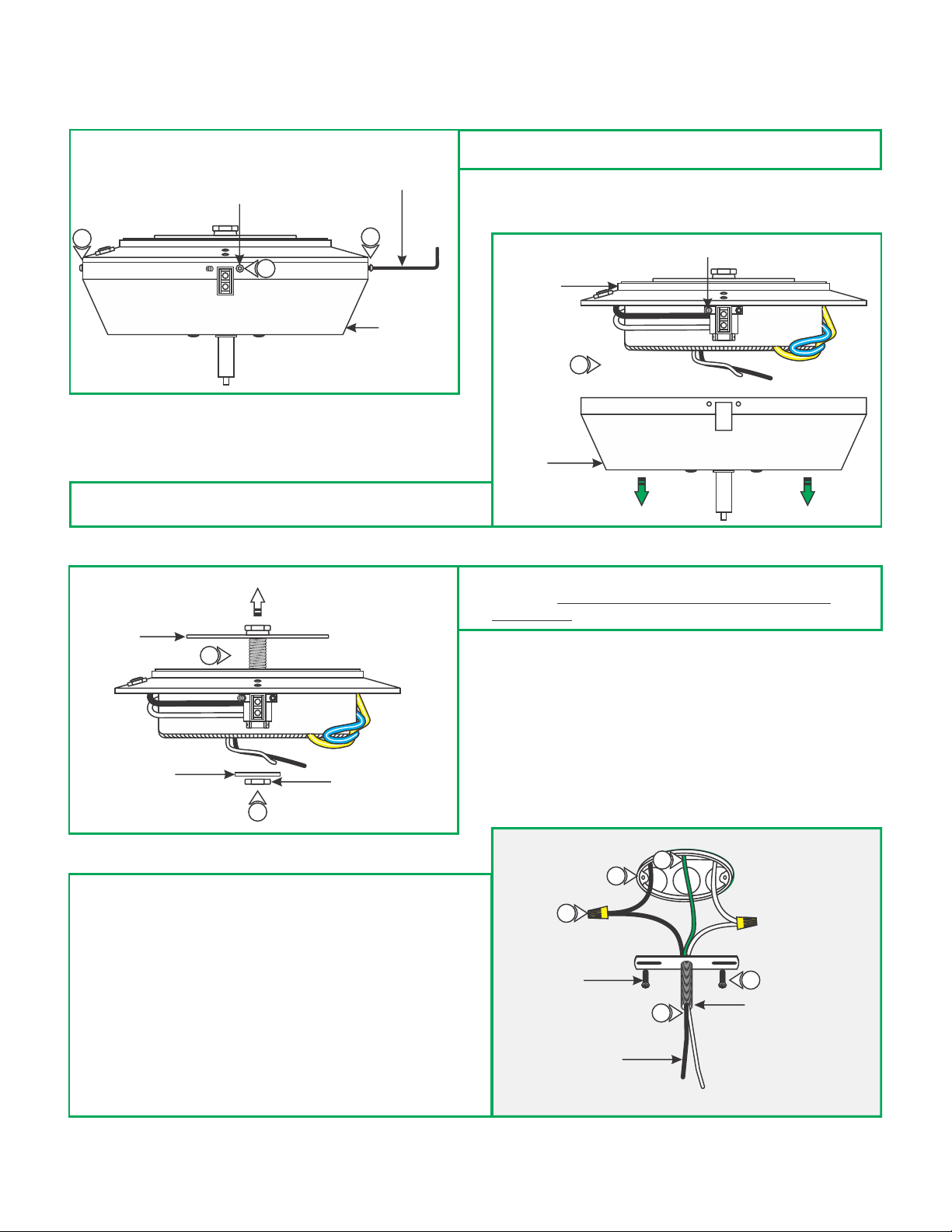
Install the Surface Mount Transformer
B
M4 BUTTON
HEAD SCREW
2MM ALLEN WRENCH
1: Loosen and remove the five M4 button head screws around
the transformer cover with the provided 2mm Allen wrench.
1
1
2: Unhook the transformer cover from the set screw and
remove it from the transformer housing.
1
COVER
D
CROSSBAR
ASSEMBLY
3
C
HOUSING
2
COVER
3: Remove the inside nut and washer to remove the crossbar
assembly. DO NOT DISASSEMBLE THE CROSSBAR
ASSEMBLY.
SET SCREW
WASHER
3
4: Connect the provided white and black extension wires to the
neutral and hot power wires respectively with the wire nuts
provided.
5: Feed the wires through the crossbar assembly nipple.
6: Place all wires and wire nut connections inside the electrical
box.
7: Mount the crossbar assembly to the electrical box with the
two provided #8-32 screws.
8: Make sure the crossbar assembly, canopy, and power supply
are grounded in accordance with local electrical codes.
INSIDE NUT
E
4
#8-32 SCREW
EXTENSION WIRES
8
6
7
5
CROSSBAR ASSEMBLY
NIPPLE
2
Page 3

F
ELECTRICAL
BOX
HOUSING
9: Feed the extension wires through the transformer housing
center hole. Slide the transformer housing onto the
crossbar assembly nipple and secure it in place by
tightening the washer and inside nut.
CROSSBAR ASSEMBLY
NIPPLE
9
EXTENSION WIRES
WASHER
INSIDE NUT
10: Connect the white transformer wire to the neutral power
wire with a wire nut.
11: Connect the black transformer wire to the hot power wire
with a wire nut.
H
G
11
10
NOTE: It is recommended that more than one person assist in
installing this fixture to avoid damage or injury.
12: Press the tab on the end of the center mounting standoff in
to feed the fixture suspension cable through. Adjust the
fixture height to desired position. Trim excess suspension
cable close to center mounting standoff.
CENTER
MOUNTING STANDOFF
TAB
13: Feed one fixture power cable through each grommet
opening in the power supply canopy.
14: Trim power cables after WARNING! RISK OF FIRE:
adjusting fixture height. Leave only enough power cable
inside the canopy to complete electrical connections. DO
NOT coil excess power cable inside canopy!
12
12
SUSPENSION CABLE
I
Trim excess
cable. DO NOT
COIL!
Trim excess
cable. DO NOT
COIL!
1313
POWER CABLEPOWER CABLE
3
Page 4

J
15
12VAC
NEU
15: Connect one fixture power wire to the white 12VAC neutral
wire from the power supply.
16: Connect the remaining fixture power wire to the yellow and
white 12VAC hot wire from the power supply.
12VAC
HOT
16
17: Place the transformer cover onto the transformer housing.
Replace and tighten the five M4 button head screws with
the 2mm Allen wrench.
Install the Lamps and Crystals
L
METAL FRAME
K
17
M4 BUTTON
HEAD SCREW
CAUTION: To reduce risk of a burn or electrical shock during
lamping, disconnect the power to the fixture.
NOTE: Use a soft cloth and fingers to install the lamp.
Use MAX 2W Type E10 Miniature or MAX 0.5W
LED lamp for each socket. Reference product specification
sheet.
Use MAX 20W or MAX 3W LED Type AR11
bayonet base halogen or lamp for Downlight version.
HOUSING
17
2MM ALLEN
WRENCH
COVER
17
SOCKET
LAMP
1
1: Screw each lamp completely into the sockets.
2: For Downlight version, install the AR11 bayonet base lamp
by pushing the lamp into the downlight socket and turning to
secure.
4
Page 5

M
CRYSTAL
2: Secure each crystal loop to a threaded post on the metal
frame. Repeat until all crystals have been mounted to the
metal frame.
METAL FRAME
2
4
 Loading...