

Page 1
1718 W. Fullerton Ave
Chicago, IL 60614
Tel: 773-770-1195
Fax: 773-935-5613
www.edgelighting.com
© 2014 Edge Lighting. All Rights Reserved.
info@edgelighting.com
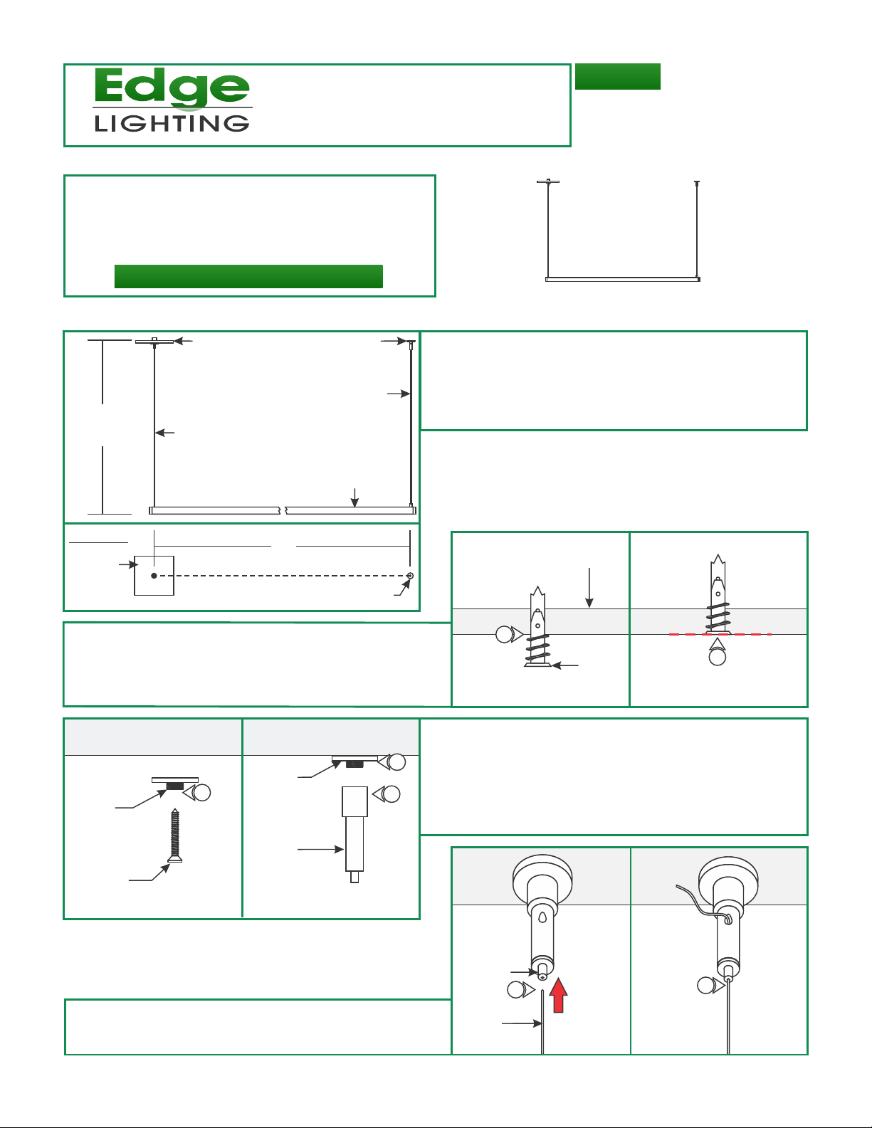
Installation Instructions for Cirrus Float End Feed
IMPORTANT INFORMATION
- This product is suitable for indoor locations.
- This instruction shows a typical installation.
- Ensure that power to the junction box is OFF before
beginning any electrical work.
SAVE THESE INSTRUCTIONS!
Install the Fixture
A
CANOPY
H
COAXIAL CABLE
STANDOFF
AIRCRAFT CABLE
1: Measure the distance between the coaxial cable and the
aircraft cable mounted on the channel. This measurement
varies on the fixture length.
2: Mark the standoff location from the center of the electrical
box for the distant achieved on step 1.
CF-D1-E-_
904-CF-D1-E-02
CHANNEL
TOP VIEW
CANOPY
3: Tap the anchors onto the marked points up to the threaded
portion with a hammer.
4: Screw in the threaded portion of the anchors with a Phillips
screwdriver.
L
STANDOFF
C
6
7
WASHER
W/THREADED
NIPPLE
#8 SCREW
WASHER
5
W/THREADED
NIPPLE
STANDOFF
POST
B
3
5: Feed the #8 screw through the washer w/threaded
nipple into the anchor.
6: Tighten the #8-32 screw completely into the anchor.
7: Tighten the standoff posts completely onto the threaded
nipple.
CEILING
ANCHOR
4
ANCHOR MUST
BE FLUSH TO CEILING
D
8: Push the tab on standoff and feed the aircraft cable from
the channel into a standoff, to hold the one end of the fixture
in place.
STANDOFF
POST TAB
AIRCRAFT
CABLE
8
8
1
Page 2
E
BRAIDED
WIRE
INNER
INSULATION
BARE WIRE
1/8"
COAXIAL CABLE
POWER
CANOPY
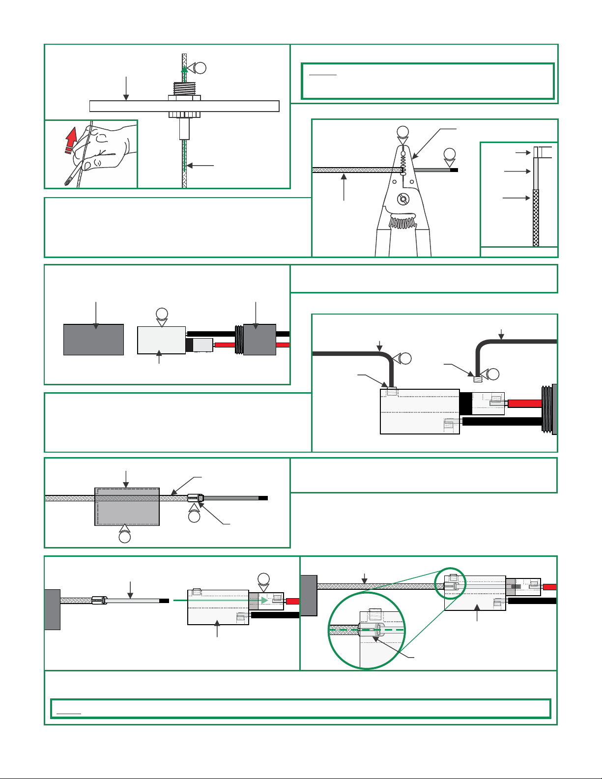
9: Feed the coaxial cable through the power feed canopy.
9
NOTE: If cable is curled or kinked, straighten by holding
between the shaft of a screwdriver and thumb and pulling the
cable through (see inset K1)
COAXIAL
CABLE
K1
10: Using the 18 AWG hole of the wire strippers, remove 1" of
the outer braided wire.
11: Using the 20 AWG hole of the wire strippers, remove 1/8"
of inner plastic insulation from the end of the coaxial cable.
G
COAXIAL
CONNECTOR
COVER
12
CONNECTOR
ASSEMBLY
13: Using the provided 1.5mm Allen Wrench, remove the M3
set screw from the coaxial connector assembly.
COAXIAL
CONNECTOR
COVER
F
10
COAXIAL
CABLE
WIRE STRIPPERS
11
12: Unscrew the coaxial connector covers and remove from the
connector assembly.
H
M4 SET
SCREW
2MM ALLEN
WRENCH
13
M3 SET
SCREW
1.5MM ALLEN WRENCH
14
14: Using the provided 2mm Allen wrench to loosen (do not
remove) the M4 set screw.
I
J
COAXIAL CONNECTOR COVER
15
COAXIAL
CABLE
17: Insert the coaxial cable into the coaxial connector until the wires of the center conductor are visible through the M3 set
BRAIDED
WIRE
16
CONNECTOR
ASSEMBLY
FERRULE
17
15: Slide the connector cover over the coaxial cable.
16: Place the ferrule over the braided wire of the coaxial cable.
COAXIAL
CABLE
CONNECTOR
ASSEMBLY
FERRULE
screw hole.
NOTE: Ensure that the split in the ferrule is aligned 90° from the M4 set screw (see inset).
2
Page 3

K
1.5MM ALLEN
WRENCH
18
M3 SET
SCREW
18: Use the provided 1.5mm Allen wrench to replace and
securely tighten the M3 set screw.
L
19
COAXIAL
CABLE
19: Use the provided 2mm Allen wrench to securely tighten the
M4 set screw until it squeezes the wire ferrule tightly to the
coaxial cable.
M
COAXIAL
CABLE
NOTE: Ensure that power to the junction box is OFF before
beginning any electrical work.
21: Connect the white transformer wire to the neutral power
wire with a wire nut.
CONNECTOR
ASSEMBLY
COAXIAL CONNECTOR
COVER
20
2MM ALLEN
WRENCH
COAXIAL
CABLE
CONNECTOR
ASSEMBLY
20: Replace the coaxial connector cover and tighten into
place.
M4 SET
SCREW
N
22
21
22: Connect the black transformer wire to the hot power wire
with a wire nut.
23: Place the transformer and transformer wires inside the
junction box.
O
25
24
26: Place all connections into the junction box.
24: Connect one red transformer wire (either one) to the black
coaxial connector wire using a wire nut
25: Connect the other red transformer wire to the red coaxial
connector wire using a wire nut.
P
POWER
CANOPY
27
CANOPY POST
#8-32
SCREWS
27: Secure the power canopy to the junction box using two #8 32 screws.
3
Page 4

Height Adjustments
Q
CANOPY
COAXIAL CABLE
GENERAL WIRING DIAGRAM
INPUT
120VAC
WHITE (NEUTRAL)
BLACK (HOT)
1
ELECTRONIC LOW
VOLTAGE DIMMER
CANOPY
POST TAB
STANDOFF
POST TAB
AIRCRAFT
CABLE
YELLOW
WHITE (NEUTRAL)
BLACK (HOT)
1: Adjust the fixture height by pushing the aircraft cable &
coaxial cable in to the standoff posts & canopy post.
2: If necessary push the tab on the standoffs & canopy post
to release the wire.
1
CHANNEL
COAXIAL
COAXIAL
CABLE
LED TRANSFORMER
RED (24VAC)
RED (24VAC)
CONNECTOR
4
 Loading...