

Page 1
1718 W. Fullerton Ave
Chicago, IL 60614
Tel: 773-770-1195
Fax: 773-935-5613
www.edgelighting.com
© 2013 Edge Lighting. All Rights Reserved.
info@edgelighting.com
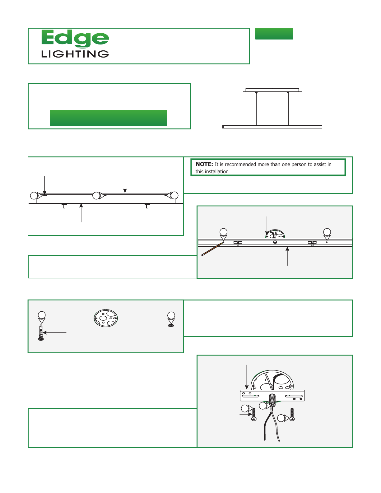
Installation Instructions for Cirrus Float Center Feed
IMPORTANT INFORMATION
- This product is suitable for indoor locations.
- This instruction shows a typical instruction.
SAVE THESE INSTRUCTIONS!
Install the Fixture
CF-D1-C-_
904-CF-D1-C-01
A
PHILLIPS SCREW
1
CANOPY
:
2 Align the mounting plate holes with the electrical box holes
and mark a point through the mounting plate holes onto the
ceiling. These points are used for the anchors.
MOUNTING PLATE
1
1
C
3
ANCHOR
4
NOTE: It is recommended more than one person to assist in
this installation
1: Loosen and remove the six Phillips screws from the canopy
to remove the mounting plate.
B
3: Tap the anchors onto the marked points up to the threaded
portion with a hammer.
4: Screw in the threaded portion of the anchors with a Phillips
screwdriver.
ELECTRICAL BOX HOLE
2 2
MOUNTING PLATE
5: Feed the power wires through the crossbar assembly
center hole.
6: Mount the crossbar assembly to the electrical box holes with
the provided #8-32 screws.
D
#8-32 SCREW
CROSSBAR ASSEMBLY
5
6
6
1
Page 2
E
MOUNTING PLATE
ELECTRICAL BOX
COVER
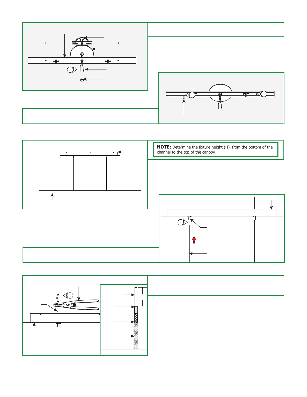
7:
Slide the cover and mounting plate center hole onto the
crossbar threaded nipple and secure it with the nut provided.
7
Secure the mounting plate to the anchors with the provided
8:
#8 screws.
POWER WIRE
NUT
G
CANOPY
H
CHANNEL
F
8
#8 SCREW
NOTE: Determine the fixture height (H), from the bottom of the
channel to the top of the canopy.
H
8
CANOPY
9: Push each coaxial cable through each cord grip inside the
canopy. Push the tab cord grip to release the cord.
I
COAXIAL
CABLE
CANOPY
WIRE STRIPPER
10
BARE WIRE
INNER
INSULATION
BREADED
WIRE
INSULATION
COAXIAL CABLE
9
STANDOFF TAB
COAXIAL CABLE
10: Use the #16 gauge hole of the AWG wire strippers to strip
1/2" of the insulation along with breaded wire and inner
wire insulation.
1/2"
2
Page 3

J
11
POWER SUPPLY
11: Connect each coaxial cable bare wire to the low voltage red
power supply wires with a wire nut.
CANOPY
COAXIAL CABLE
12: Make sure the mounting plate is grounded in accordance
with local electrical codes.
13: Connect the white transformer wire to the neutral power
wire with a wire nut.
14: Connect the black transformer wire to the hot power
wire with a wire nut.
L
16
15
#8-32 SCREW
16
K
12
13
15: Place all the wires and wire nut connections inside the
canopy.
16: Align and secure the canopy to the mounting plate by
tightening the six #8-32 screws.
M
14
CANOPY
17: To make any adjustments to the fixture height, push the
tabs on the canopy to slide the fixture up and down until
the desired height is achieved. Release the tab to lock the
coaxial cable in place.
GENERAL WIRING DIAGRAM
INPUT
120VAC
WHITE (NEUTRAL)
BLACK (HOT)
ELECTRONIC LOW
VOLTAGE DIMMER
YELLOW
WHITE (NEUTRAL)
BLACK (HOT)
LED TRANSFORMER
RED (24VAC)
RED (24VAC)
17
STANDOFF TAB
COAXIAL CABLE
CHANNEL
COAXIAL
CABLE
3
 Loading...