

Page 1
© 2012 Edge Lighting. All Rights Reserved.
1718 W. Fullerton Ave
Chicago, IL 60614
Tel: 773-770-1195
Fax: 773-935-5613
www.edgelighting.com
info@edgelighting.com
CC-WW-_
Installation Instructions for Cirrus Channel, Wall Wash Lens
IMPORTANT INFORMATION
- This instruction shows a typical installation.
SAVE THESE INSTRUCTIONS!
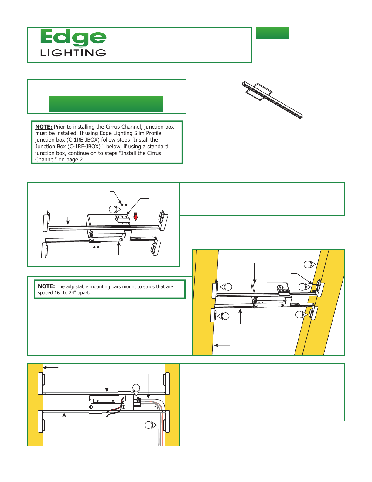
NOTE: Prior to installing the Cirrus Channel, junction box
must be installed. If using Edge Lighting Slim Profile
junction box (C-1RE-JBOX) follow steps "Install the
Junction Box (C-1RE-JBOX) " below, if using a standard
junction box, continue on to steps "Install the Cirrus
Channel" on page 2.
Install the Junction Box (C-1RE-JBOX)
: Mount each adjustable mounting bar to one side of the
A
PHILLIPS SCREW
ADJUSTABLE
MOUNTING BAR
MOUNTING
BRACKET
1
1
electrical box (mounts to any side of the housing depending
on the orientation of the channel) and secure them with the
mounting brackets and two Phillips screws provided.
904-CC-WW-01
ELECTRICAL BOX
NOTE: The adjustable mounting bars mount to studs that are
spaced 16" to 24" apart.
2:
Select the location between the two studs for the electrical
box to be mounted.
3: Place the adjustable mounting bars between the studs.
4: Make sure the lips on the adjustable mounting bars are
against the studs. Secure the adjustable bars to the
studs with the eight #8 screws.
C
STUD
ADJUSTABLE
MOUNTING BAR
ELECTRICAL
BOX
CONDUIT
5
6
B
4
4
5: Remove a knockout to install the power line conduit.
6: Install the conduit and run the low voltage 24V DC power
wires coming from the remote power supply to the
electrical box.
7: Refer to the instruction provided with the power supply to
properly wiring diagram.
ELECTRICAL
BOX
ADJUSTABLE
MOUNTING BAR
STUD
2
#8 SCREW
4
4
1
Page 2
D
4"
9
0.7"
DRYWALL
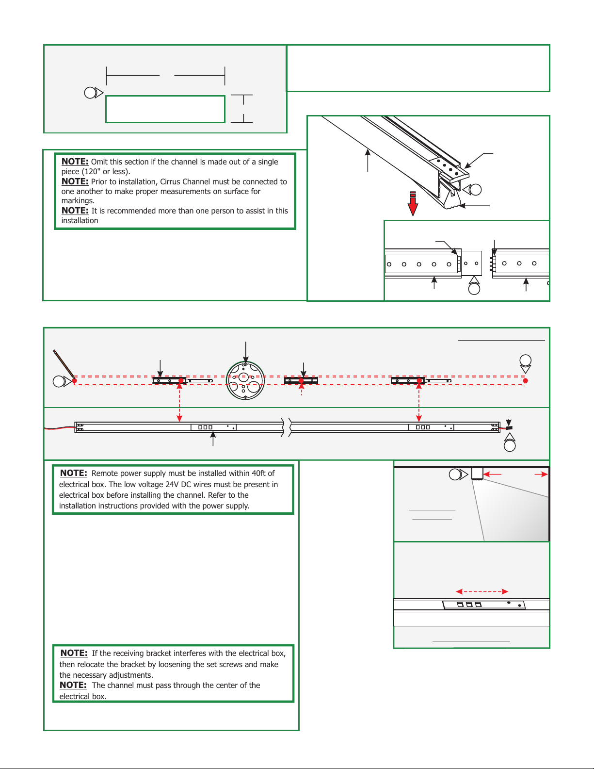
Omit this section if the channel is made out of a single
NOTE:
piece (120" or less).
NOTE: Prior to installation, Cirrus Channel must be connected to
one another to make proper measurements on surface for
markings.
NOTE: It is recommended more than one person to assist in this
installation
1: Lift a section of the lens at the end of the channels where
the connectors are visible. Slide the channel over the joiner
bracket make sure that the male & female connectors mate
properly.
8: Mark a 4" x 0.7" rectangle on drywall where the electrical
box opening will be located.
9: Cut out the marked square(s) and install the drywall.
Connecting the Channel
E
JOINER
BRACKET
CHANNEL
1
LENS
FEMALE
CONNECTOR
MALE
CONNECTOR
2: Push the lens back into the channel.
Install the Channel
F
1
POWER FEED END
OF CHANNEL
BOTTOM OF CHANNEL
NOTE: Remote power supply must be installed within 40ft of
electrical box. The low voltage 24V DC wires must be present in
electrical box before installing the channel. Refer to the
installation instructions provided with the power supply.
1: Wall wash channel mounts in one direction, 24" away
from the wall to properly light the desired area.
Choose the cord on one end that is closest to the electrical
box. Cut the unused cord leaving 2" exposed. Wrap the
end of the unused cord with electrical tape.
2: Lay the channel to the desired location & make all
necessary markings which will consist of the channel ends,
locking clips and mounting clips. Mounting clips must be
installed every 20" from each locking clip, locking
mounting clips are not necessary for channels
under 2ft.
NOTE: If the receiving bracket interferes with the electrical box,
then relocate the bracket by loosening the set screws and make
the necessary adjustments.
NOTE: The channel must pass through the center of the
electrical box.
3: After all markings and required measurements are done,
take apart channels from each other.
RECEIVING BRACKET
JUNCTION BOX
MOUNTING
CLIP (C-MCL)
EVERY 20 INCHES
CHANNEL
LOCKING CLIPLOCKING CLIP
INSTALLED
CHANNEL
IF NECESSARY, RECEIVING
BRACKET CAN BE ADJUSTED
BY LOOSENING THE SET SCREWS.
MOVE BRACKET TO THE DESIRED POSITION
AND TIGHTEN THE SET SCREWS.
BACK OF CHANNEL
1
MARKING LOCATION
1
JOINER CHANNEL
1
CHANNEL
END
TAPE
1
24" AWAY
FROM WALL
2
Page 3

G
SURFACE
Steps 4 and 5 are for drywall mounting. Omit these steps
NOTE:
if mounting the clips to a wood surface directly.
4: Tap the anchors onto the marked points up to the threaded
portion with a hammer.
4
ANCHOR
BE FLUSH TO WALL
5
ANCHOR MUST
H
JUNCTION BOX
6: If using the standard Junction box only, mount the
crossbar to the electrical box holes with the two #8-32
screws provided.
I
#6 SCREW &
WASHER
LOCKING CLIP
5: Screw in the threaded portion of the anchors with a Phillips
screwdriver.
CROSSBAR
6
6
MOUNTING
CLIP (C-MCL)
#8-32 SCREW
7
7: Line up the locking clips & mounting clips to anchor holes
and secure them by tightening the two #6 screws with
washers under the head into each clip.
7
J
LOCKING CLIP
8: Connect the red power supply (24VDC+) wire to red strip
wire with a wire nut inside the electrical box.
9: Connect the black power supply (24VDC+) wire to black
strip wire with a wire nut inside the electrical box.
8
MOUNTING
CLIP (C-MCL)
9
7
WIRE
MANAGEMENT
CLIP
CORD
CHANNEL
10
10: Snap the wire management clip to hold the cable in place if
necessary.
3
Page 4

K
LOCKING CLIP
11
BACK OF CHANNEL
LOCKING
CLIP
11: Carefully snap fixture body into the locking/mounting clips
then slide (2") into receiving bracket to lock in place. Make
sure not to nick the wires.
12: If applicable, connect the remaining channels by following
"Connecting the Channel" on page 2. Then secure by
repeating step 11 (above).
RECEIVING BRACKET
MOUNTING
CLIP (C-MCL)
L
CHANNEL
SCREW
13
13: If using the standard Junction box, Place each canopy
piece against the crossbar and secure it to the electrical box
holes with the provided screws.
CHANNEL
CANOPY
13
 Loading...