

Page 1
© 2014 Edge Lighting. All Rights Reserved.
1718 W. Fullerton Ave
Chicago, IL 60614
Tel: 773-770-1195
Fax: 773-935-5613
www.edgelighting.com
info@edgelighting.com
CCS-R1-_
Installation Instructions for Cirrus Channel Suspension R1,
Rectangular 1" Lens
IMPORTANT INFORMATION
- This product is suitable for indoor locations.
- This instruction shows a typical installation.
SAVE THESE INSTRUCTIONS!
Connecting the Channel
904-CCS-R1-03
A
CHANNEL
TOP OF CHANNEL
FEMALE
CONNECTOR
FRONT
VIEW
3: Position the joiner bracket where the two channels meet.
Tighten four #6-32 set screws using the 1/16 Allen wrench.
CHANNEL
JOINER
BRACKET
1
LENS
MALE
CONNECTOR
JOINER CHANNEL
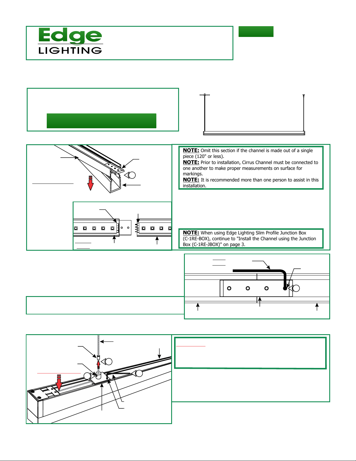
NOTE: Omit this section if the channel is made out of a single
piece (120" or less).
NOTE: Prior to installation, Cirrus Channel must be connected to
one another to make proper measurements on surface for
markings.
NOTE: It is recommended more than one person to assist in this
installation.
1: Lift a section of the lens at the end of the channels where
the connectors are visible. Slide the channel over the joiner
bracket make sure that the male & female connectors mate
properly.
2: Push the lens back into the channel.
NOTE: When using Edge Lighting Slim Profile Junction Box
(C-1RE-BOX), continue to "Install the Channel using the Junction
Box (C-1RE-JBOX)" on page 3.
B
CHANNEL CHANNEL
BACK
VIEW
1/16 ALLEN
WRENCH
JOINER BRACKET
#6-32 SET
SCREW
3
Adjusting Cable Position
C
STRAIN RELIEF
#4-40 SET SCREW
HOLD CABLE HERE
4
SLIDING POST
COAXIAL CABLE
5
0.05" ALLEN WRENCH
#4-40 SET SCREW
4
CHANNEL
WARNING: To avoid damaging the coaxial cable electrical
connection, make sure that the end of the coaxial cable coming
out of the fixture is held with thumb before relocating sliding
posts.
1: Loosen (DO NOT REMOVE) the #4-40 set screw on the
sliding post bushing and bed with a 0.05" Allen wrench.
2: Slide the strain relief tube out of the sliding post using a pair
of needle-nose pliers.
1
Page 2
D
COAXIAL CABLE
3
SLIDING
POST
!CAUTION! Tightening the strain relief set screw CANNOT
BE REVERSED. Only tighten the set screw AFTER the cable
location is set properly.
4: Insert the strain relief tube back inside the sliding post
bushing and tighten the #4-40 set screw with the 0.05"
Allen wrench.
CHANNEL
3
0.05" ALLEN
WRENCH
#4-40 SET
SCREW
3: Carefully move the sliding post to the predetermined location
on channel and tighten the #4-40 set screw on the sliding
post bed with the 0.05" Allen wrench.
E
0.05" ALLEN
WRENCH
4
#4-40 SET
SCREW
STRAIN RELIEF
4
SLIDING
POST
F
0.05"ALLEN
WRENCH
#4-40 SET SCREW
5
5
5
SLIDING
POST
Install the Fixture
G
H
CANOPY
COAXIAL CABLE
AIRCRAFT CABLE
STRAIN RELIEF
STANDOFF
AIRCRAFT CABLE
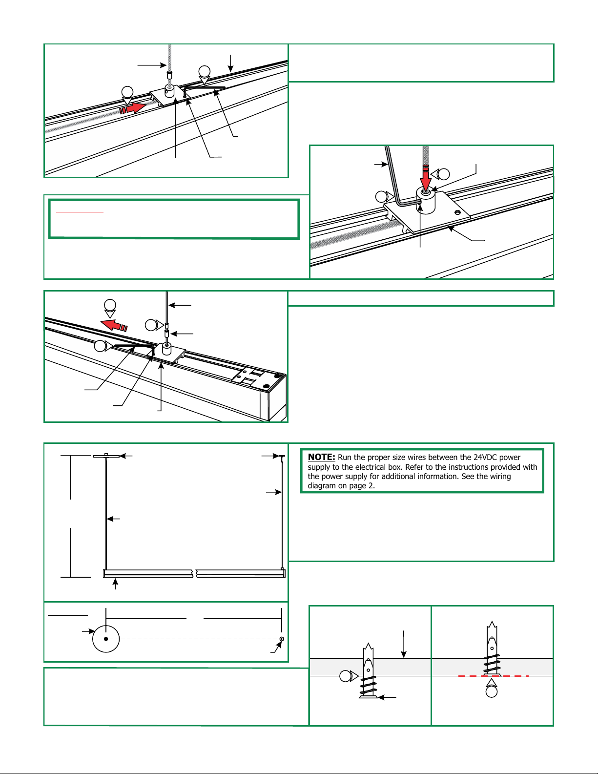
5: Repeat Steps 1 through 4 for aircraft cable side.
NOTE: Run the proper size wires between the 24VDC power
supply to the electrical box. Refer to the instructions provided with
the power supply for additional information. See the wiring
diagram on page 2.
1: Measure the distance between the coaxial cable and the
aircraft cable mounted on the channel. This measurement
varies on the fixture length.
2: Mark the standoff location from the center of the electrical
box for the distant achieved on step 1.
CHANNEL
TOP VIEW
L
CANOPY
STANDOFF
3: Tap the anchors onto the marked points up to the threaded
portion with a hammer.
4: Screw in the threaded portion of the anchors with a Phillips
screwdriver.
H
CEILING
3
ANCHOR
BE FLUSH TO WALL
4
ANCHOR MUST
2
Page 3

I
BRAIDED
WIRE
INNER
INSULATION
BARE WIRE
1/8"
COAXIAL CABLE
WASHER
WASHER
5
W/THREADED
NIPPLE
#8 SCREW
W/THREADED
NIPPLE
STANDOFF
POST
8: Push the tab on standoff while feeding the aircraft cable
coming from the channel into a standoff so that it holds one
end of the fixture in place.
6
7
5: Feed the #8 screw through the washer w/threaded
nipple into the anchor.
6: Tighten the #8 screw completely into the anchor.
7: Tighten the standoff posts completely onto the threaded
nipple.
J
STANDOFF
POST TAB
8
AIRCRAFT
CABLE
8
K
POWER
CANOPY
9
COAXIAL
CABLE
K1
10: Using the 18 AWG hole of the wire strippers, remove 1" of
the outer braided wire.
11: Using the 20 AWG hole of the wire strippers, remove 1/8"
of inner plastic insulation from the end of the coaxial cable.
M
COAXIAL
CONNECTOR
COVER
12
COAXIAL
CONNECTOR
COVER
9: Feed the coaxial cable through the power feed canopy.
NOTE: If cable is curled or kinked, straighten by holding
between the shaft of a screwdriver and thumb and pulling the
cable through (see inset K1)
L
10
COAXIAL
CABLE
WIRE STRIPPERS
11
12: Unscrew the coaxial connector covers and remove from the
connector assembly.
N
2MM ALLEN
WRENCH
1.5MM ALLEN WRENCH
CONNECTOR
ASSEMBLY
13: Using the provided 1.5mm Allen Wrench, remove the M3
set screw from the coaxial connector assembly.
14: Using the provided 2mm Allen wrench to loosen (do not
remove) the M4 set screw.
M4 SET
SCREW
13
M3 SET
SCREW
14
3
Page 4

O
COAXIAL
CONNECTOR
COVER
15
BRAIDED
WIRE
FERRULE
15: Slide the connector cover over the coaxial cable.
16: Place the ferrule over the braided wire of the coaxial cable.
16
P
COAXIAL
COAXIAL
CABLE
CONNECTOR
ASSEMBLY
17: Insert the coaxial cable into the coaxial connector until the wires of the center conductor are visible through the M3 set
screw hole.
NOTE: Ensure that the split in the ferrule is aligned 90° from the M4 set screw (see inset).
Q
1.5MM ALLEN
WRENCH
18
17
18: Use the provided 1.5mm Allen wrench to replace and
securely tighten the M3 set screw.
M3 SET
SCREW
R
COAXIAL
CABLE
CONNECTOR
ASSEMBLY
CABLE
2MM ALLEN
WRENCH
CONNECTOR
ASSEMBLY
FERRULE
19
M4 SET
SCREW
19: Use the provided 2mm Allen wrench to securely tighten the
M4 set screw until it squeezes the wire ferrule tightly to the
coaxial cable.
S
COAXIAL
20
COAXIAL
CABLE
CONNECTOR
COVER
COAXIAL
CABLE
CONNECTOR
ASSEMBLY
20: Replace the coaxial connector cover and tighten into
place.
4
Page 5

T
NOTE: Ensure remote DC power supply wires are present in
the junction box before continuing.
21: Connect the black remote power supply wire to the black
coaxial connector wire using a wire nut.
21
22
23: Place all connections into the junction box.
24: Secure the power canopy to the junction box using two #8-
32 screws.
Height Adjustments
V
1
CANOPY
CANOPY
POST TAB
22: Connect the black remote power supply wire to the black
coaxial connector wire using a wire nut.
U
POWER
CANOPY
24
1: Adjust the fixture height by pushing the aircraft cable &
coaxial cable in to the standoff posts & canopy post.
2: If necessary push the tab on the standoffs & canopy post
to release the wire.
CANOPY POST
#8-32
SCREWS
COAXIAL CABLE
GENERAL WIRING DIAGRAM
WHITE (NEUTRAL)
INPUT
120VAC
RED 120VAC (HOT)
PURPLE 1-10V
GRAY 1-10V
DIMMING
BLACK (HOT)
GND
PHILIPS:
SUNRISE
SR1200ZTUNV
STANDOFF
POST TAB
VOLTAGE
DROP
AIRCRAFT
CABLE
1
96W, 24VDC LOW VOLTAGE WIRE SIZE CHART
WIRE LENGTH
IN FT
WIRE SIZE 14 AWG
VOLTAGE AT END
OF THE WIRE
UP TO 33FT3%34FT-52FT
12 AWG 10 AWG 8 AWG
23.28 VDC 23.29 VDC 23.28 VDC
53FT-86FT 87FT-130FT
PSB-96W-010-24VDC
input 120VAC
WH (N)
BK (L)
input 0-10V
PUR
GRY
RED (24VDC+)
BLUE (RETURN-)
YELLOW (DIM RETURN-)
RED 24VDC+
BLACK 24VDC-
24VDC
23.28 VDC
COAXIAL
CONNECTOR
COAXIAL
CABLE
CHANNEL
5
 Loading...