

Page 1
© 2013 Edge Lighting. All Rights Reserved.
1718 W. Fullerton Ave
Chicago, IL 60614
Tel: 773-770-1195
Fax: 773-935-5613
www.edgelighting.com
info@edgelighting.com
CC-D1-2WDC-_
CC-D1-5WDC-_
Installation Instructions for Cirrus Channel, Direct 1" Lens, 24VDC
IMPORTANT INFORMATION
- This instruction shows a typical installation.
- Per NEC Article 410.16(A)(1)(3) & 410.16(C)(5). Approved
for Closet Storage Areas.
SAVE THESE INSTRUCTIONS!
Connecting the Channel
A
CHANNEL
FEMALE
CONNECTOR
TOP OF CHANNEL
JOINER BRACKET
1
LENS
MALE
CONNECTOR
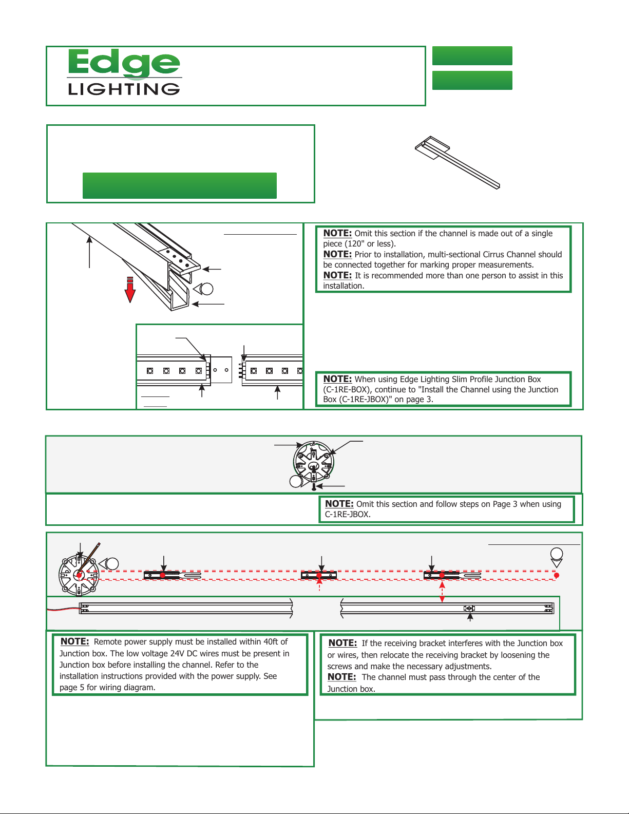
NOTE:
Omit this section if the channel is made out of a single
piece (120" or less).
NOTE: Prior to installation, multi-sectional Cirrus Channel should
be connected together for marking proper measurements.
NOTE: It is recommended more than one person to assist in this
installation.
1: Lift a section of the lens at the end of the channels where
the connectors are visible. Slide the channel over the joiner
bracket make sure that the male & female connectors mate
properly.
2: Push the lens back into the channel.
904-CC-D1-02
NOTE:
When using Edge Lighting Slim Profile Junction Box
FRONT
VIEW
CHANNEL
JOINER CHANNEL
(C-1RE-BOX), continue to "Install the Channel using the Junction
Box (C-1RE-JBOX)" on page 3.
Install Channel on Standard Junction Box W/Plaster Ring or Octagon Box
B
JUNCTION BOX
1
1: Mount the crossbar to the Junction box holes with the two
#8-32 screws provided.
JUNCTION BOX
C
2
BOTTOM OF CHANNEL
LOCKING CLIP
MOUNTING
CLIP (C-MCL)
EVERY 20 INCHES
NOTE: Remote power supply must be installed within 40ft of
Junction box. The low voltage 24V DC wires must be present in
Junction box before installing the channel. Refer to the
installation instructions provided with the power supply. See
page 5 for wiring diagram.
2: Begin installation using side of the channel with power wire.
Lay channel to the desired location & make all necessary
markings which will consist of the channel ends, locking clips
and mounting clips. Mounting clips must be installed 20"
from each other. Locking clips are not necessary for
channels under 2ft.
NOTE:
C-1RE-JBOX.
NOTE: If the receiving bracket interferes with the Junction box
or wires, then relocate the receiving bracket by loosening the
screws and make the necessary adjustments.
NOTE: The channel must pass through the center of the
Junction box.
3: After all markings and required measurements are done,
take the channels apart from each other.
CROSSBAR
#8-32 SCREW
Omit this section and follow steps on Page 3 when using
MARKING LOCATION
LOCKING CLIP
CHANNEL END
RECEIVING BRACKET
3
1
Page 2
D
SURFACE
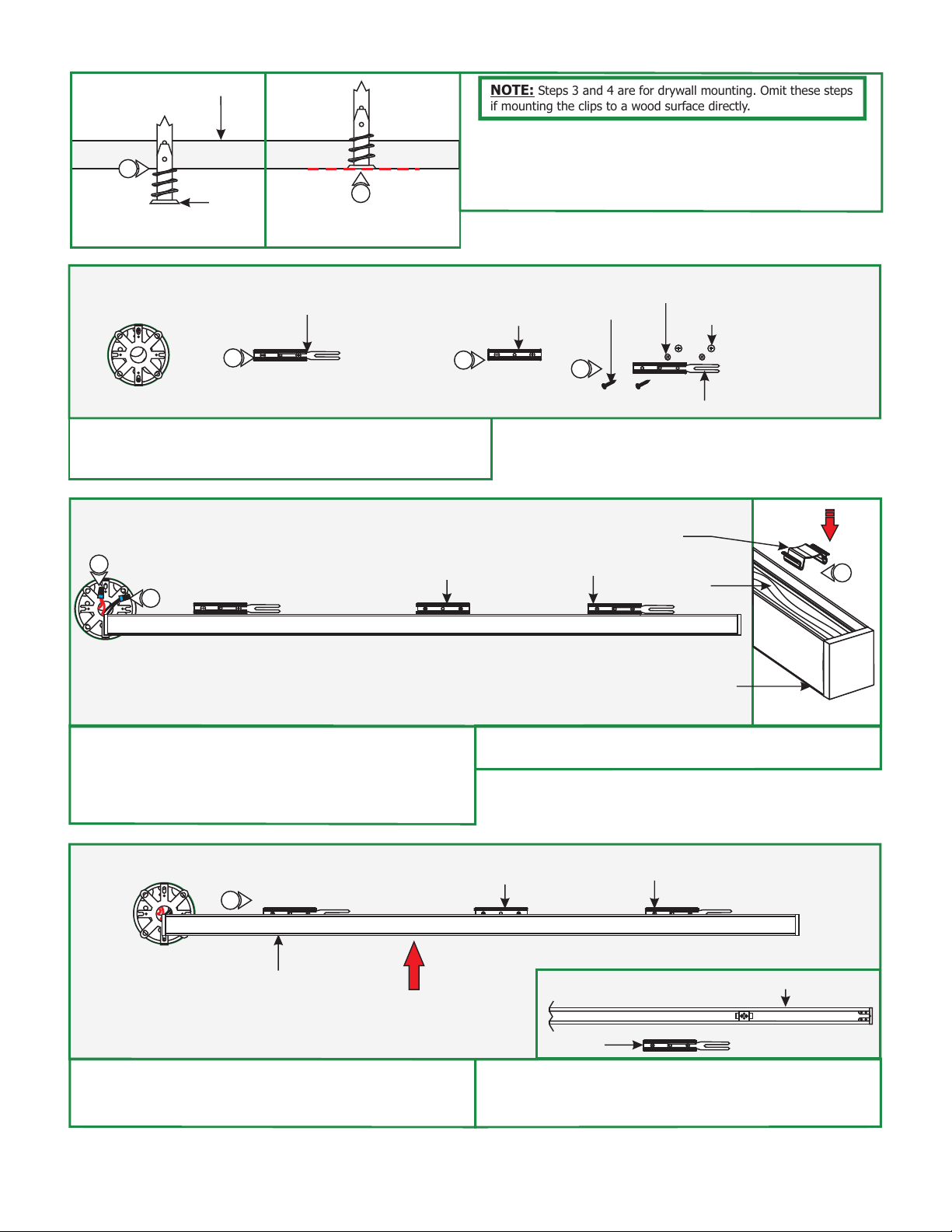
NOTE:
Steps 3 and 4 are for drywall mounting. Omit these steps
if mounting the clips to a wood surface directly.
4: Tap the anchors onto the marked points up to the threaded
portion with a hammer.
4
5: Screw in the threaded portion of the anchors with a Phillips
screwdriver.
ANCHOR
5
ANCHOR MUST
BE FLUSH TO WALL
E
LOCKING CLIP
6
6: Line up the locking clips & mounting clips to anchor holes
and secure them by tightening the two #6 screws through
the clip holes followed by the washers into the anchors.
F
7
8
MOUNTING
CLIP (C-MCL)
MOUNTING
CLIP (C-MCL)
6
#6 SCREW
6
LOCKING CLIP
WASHER
(OPTIONAL)
ANCHOR
LOCKING CLIP
WIRE
MANAGEMENT
CLIP
9
CORD
CHANNEL
7: Connect the red power supply (24VDC+) wire to red strip
wire with a wire nut inside the Junction box.
8: Connect the black power supply (24VDC+) wire to black
strip wire with a wire nut inside the Junction box.
G
10
CHANNEL
10: Carefully snap channel onto the locking/mounting clips
then slide 2" into receiving bracket to lock in place. Make
sure not to nick the wires.
9: Snap the wire management clip to hold the cable in place if
necessary.
MOUNTING
CLIP (C-MCL)
BACK OF CHANNEL
LOCKING CLIP
RECEIVING BRACKET
LOCKING
CLIP
11: If applicable, connect the remaining channels by following
"Connecting the Channel" on page 1. Then secure by
repeating step 10 (above).
2
Page 3

H
12
12
ALLEN
WRENCH
SCREW
CHANNEL
CANOPY
12: Place each canopy piece against the channel & line up the
canopy hole with the crossbar hole. Secure the canopy in
place with the screw & Allen wrench provided.
Install the Channel using the Junction Box (C-1RE-JBOX)
I
ADJUSTABLE
MOUNTING BAR
VERTICAL
ORIENTATION
PHILLIPS
SCREW
3
2
1
1
2
3
JUNCTION
BOX
1
MOUNTING
BRACKET
1: Mount each adjustable mounting bar to one side of the
junction box (mounts to any side of the housing depending
on the orientation of the channel) and secure them with the
mounting brackets and two Phillips screws provided.
HORIZONTAL
ORIENTATION
JUNCTION
BOX
1
3
3
2
2
1
1
NOTE: The adjustable mounting bars mount to studs that are
spaced 16" to 24" apart.
Select the location between the two studs for the Junction
2:
box to be mounted.
3: Place the adjustable mounting bars between the studs.
4: Make sure the lips on the adjustable mounting bars are
against the studs. Secure the adjustable bars to the
studs with the eight #8 screws.
K
CONDUIT
JUNCTION BOX
5
STUD
J
JUNCTION BOX
4
4
ADJUSTABLE
MOUNTING BAR
STUD
2
#8 SCREW
4
4
5: Remove a knockout to install the power line conduit.
6: Install the conduit and run the low voltage 24V DC power
wires coming from the remote power supply to the
Junction box.
ADJUSTABLE
MOUNTING BAR
NOTE: Remote power supply must be installed within 40ft of
Junction box. The low voltage 24V DC wires must be present in
Junction box. See wiring diagram on page 5 for more information.
3
Page 4

L
7:
RECTANGLE
OPENING
DRYWALL
Mark a rectangle shape on drywall where the junction box
opening will be located depending on selected position.
8: Cut out the marked rectangle opening, using a "Dremel
7
8
WOOD & DRYWALL
CUTTING BIT
DREMEL
MULTI-MAX
Multi-Max" with the "wood & drywall" cutting bit.
9: Install & finish drywall.
M
POWER FEED END
BOTTOM OF CHANNEL
JUNCTION BOX
OPENING
10
OF CHANNEL
MOUNTING
CLIP (C-MCL)
EVERY 20 INCHES
10: Start off the installation using the channel with the power
wire. Lay the channel to the desired location & make all
necessary markings which will consist of the channel ends,
locking clips and mounting clips. Mounting clips must be
installed every 20" from each locking clip, locking
mounting clips are not necessary for channels under
2ft.
N
LOCKING CLIP
MOUNTING
CLIP (C-MCL)
12
LOCKING CLIP
RECEIVING BRACKET
MARKING LOCATION
10
CHANNEL
END
NOTE: If the receiving bracket interferes with the Junction box,
then relocate the bracket by loosening the set screws and make
the necessary adjustments.
NOTE: The channel must pass through the center of the
Junction box.
11: After all markings and required measurements are done,
take the channels apart from each other.
WASHER
#6 SCREW
(OPTIONAL)
ANCHOR
12
12: Line up the locking clips & mounting clips to anchor holes
and secure them by tightening the two #6 screws through
the clip holes followed by the washers into the anchors.
JUNCTION BOX
O
OPENING EDGE
PLASTER THE EDGE OF
THE JUNCTION BOX
13
13
SCREW
GOOF PLATE
(ONLY USE IF JAGGED
PLASTER EDGE, PAINT
TO MATCH)
LOCKING CLIP
13: Optional: Use the Goof Plate if the junction box
opening has a lot of imperfection/jagged edges. Install the
provided goof plate (paint to match prior) with the two
screws.
4
Page 5

P
14
15
LOCKING CLIP
MOUNTING
CLIP (C-MCL)
LOCKING
BRACKET
WIRE
MANAGEMENT
CLIP
CORD
CHANNEL
16
14: Connect the red power supply (24VDC+) wire to red strip
wire with a wire nut inside the Junction box.
15: Connect the black power supply (24VDC+) wire to black
strip wire with a wire nut inside the Junction box.
96W, 24VDC LOW VOLTAGE WIRE SIZE CHART
3%
VOLTAGE
DROP
GENERAL WIRING DIAGRAM
WHITE (NEUTRAL)
INPUT
120VAC
GND
BLACK (HOT)
LIGHTOLIER:
ZP600FAM120
CONTROLLER
RED 120VAC (HOT)
PURPLE 1-10V
GRAY 1-10V
DIMMING
WIRE LENGTH
IN FT
WIRE SIZE
VOLTAGE AT END
OF THE WIRE
PSB-96W-010-24VDC
UP TO 33FT
14 AWG
23.28 VDC
input 120VAC
WH (N)
BK (L)
input 0-10V
PUR
GRY
16: Snap the wire management clip to hold the cable in place if
necessary.
34FT-52FT
12 AWG
23.29 VDC
RED (24VDC+)
BLUE (RETURN-)
YELLOW (DIM RETURN-)
53FT-86FT 87FT-130FT
10 AWG 8 AWG
23.28 VDC 23.28 VDC
24VDC
RED 24VDC+
BLACK 24VDC-
CIRRUS CHANNEL
5
 Loading...