

Page 1
© 2009 Edge Lighting. All Rights Reserved.
1718 W. Fullerton Ave
Chicago, IL 60614
Tel: 773-770-1195
Fax: 773-935-5613
www.edgelighting.com
info@edgelighting.com
M-BOX-_
M2- -_BOX
FJ- -_BOX
904-BOX-02
Installation Instructions for
Box Pro-Aim
IMPORTANT SAFETY INSTRUCTIONS
To reduce the risk of fire, electrical shock, exposure to
excessive UV radiation, or injury to persons:
- Use this fixture indoors only.
- Do not look directly at the lamp while the fixture is on.
- RISK OF FIRE: Use only the type of lamp and maximum
wattage indicated in this instruction manual.
- Never cover the halogen lamp with anything other than a
lamp shield provided by Edge Lighting and never place
flammable material close to the fixture.
- Never turn the fixture on and off by connecting and
disconnecting the halogen lamp.
- Do not touch the fixture head, shade or lamp shield while
the fixture is on. These surfaces may be VERY HOT.
- Do not touch lamp at anytime. Use a soft cloth. Oil from skin
may damage lamp.
- It is normal for a new halogen lamp to produce minor
smoke when first turned on.
- Do not operate the luminaire with a missing or damaged
shield.
- Turn power off and allow to cool before replacing lamp.
IMPORTANT INFORMATION
- This product is ETL listed for indoor dry locations.
- This product is not restricted to certain height installation.
It is approved to be used at any height above the floor.
- Applicable accessories are Hexcell Louver, Glass Lenses &
MR16 Snout.
SAVE THESE INSTRUCTIONS!
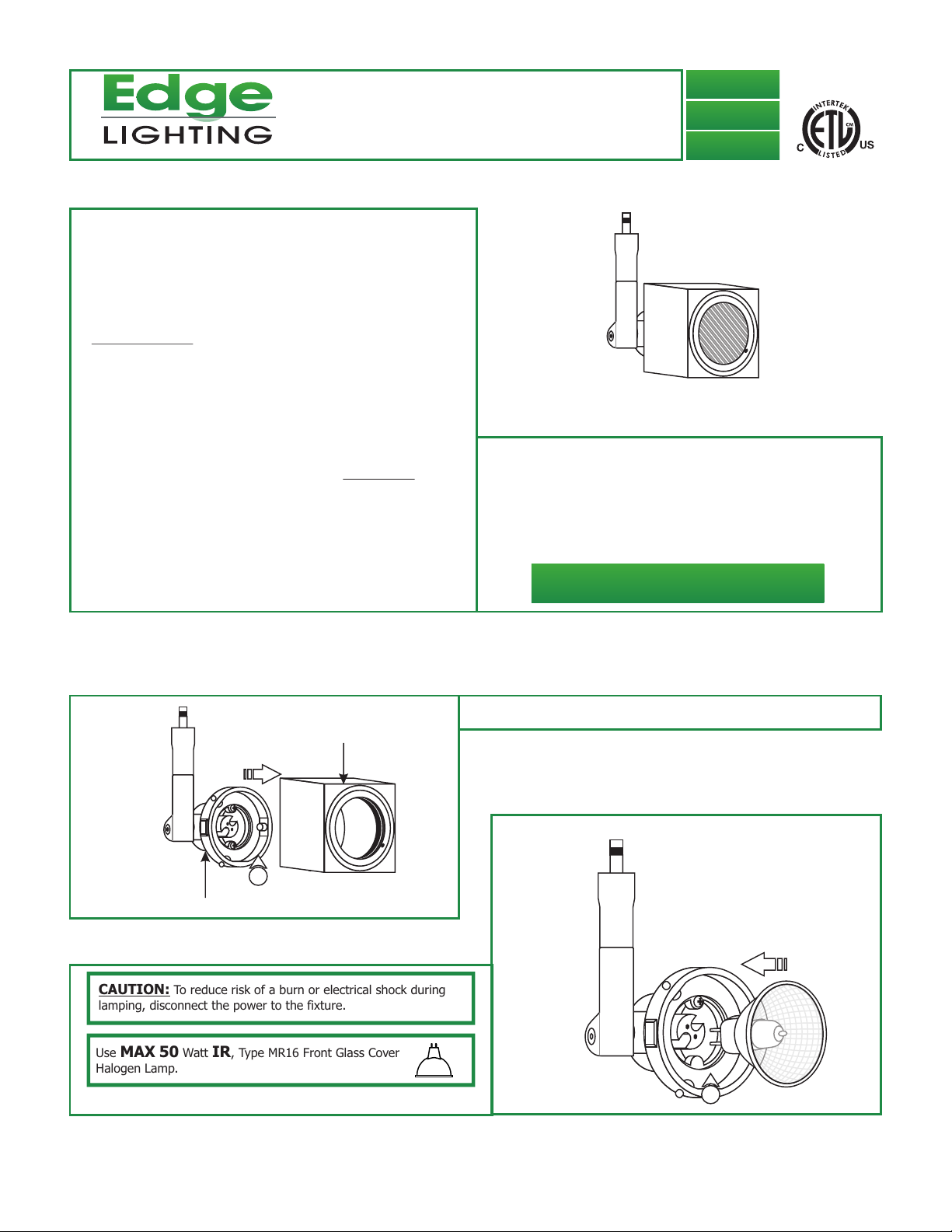
Install the Lamp & Lens Accessory
A
SHADE
1
FIXTURE BODY
CAUTION: To reduce risk of a burn or electrical shock during
lamping, disconnect the power to the fixture.
Use MAX 50 Watt IR, Type MR16 Front Glass Cover
Halogen Lamp.
2: Push the lamp pins completely into the socket holes.
1: Pull the shade completely off of the fixture body.
B
2
1
Page 2
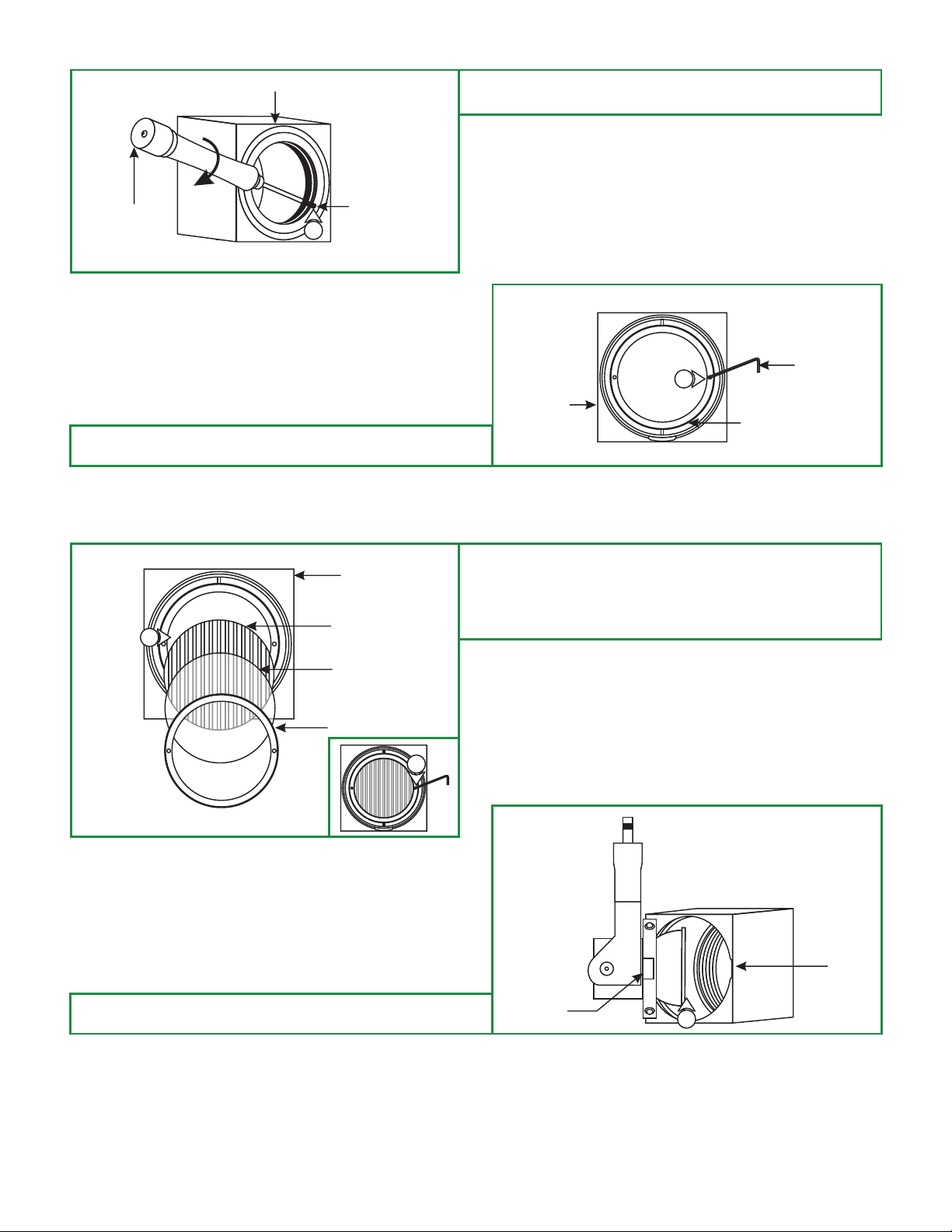
C
SHADE
3: ighten the M4 set screw on the front of the shade with the
T
2mm Allen driver provided.
2MM ALLEN
DRIVER
4:
From the inside of the shade, use a small Allen wrench or a
pen point to loosen and remove the lens holder ring.
E
5
M4 SET SCREW
3
SHADE
LENS
D
SMALL ALLEN
4
4
SHADE
LENS HOLDER RING
Place the lens(es), or a combination of a lens and hexcell
5:
louver into the shade.
6: Replace and tighten the lens holder ring to secure the lenses
in place.
WRENCH
LENS
LENS HOLDER RING
6
Line up the notch on the shade with the tabs on the fixture
7:
body and push it completely until it snaps in place properly.
F
FIXTURE
BODY TAB
SHADE
NOTCH
7
2
Page 3

Install the Box to the Monorail (MC-FJ-_)
G
MONORAIL FAST
JACK HOUSING
HOUSING
CONNECTOR
(DISCARD)
2: Place the Monorail Fast Jack housing onto the Monorail and
use fingers to tighten the Box housing connector to the Fast
Jack housing. Make sure that the Box housing
connector is not cross threaded.
1
1: Remove the Monorail housing connector from the Monorail
Fast Jack housing and discard it.
MONORAIL FAST
H
JACK HOUSING
2
MONORAIL
BOX HOUSING
CONNECTOR
Install the Box to Monorail 2 Circuit Connector (M2C-FJ-_)
I
HOUSING
CONNECTOR
(DISCARD)
MONORAIL 2 CIRCUIT
FAST JACK HOUSING
1
1: Remove the Monorail 2 Circuit housing connector from the
Monorail 2 Circuit Fast Jack housing and discard it.
MONORAIL 2 CIRCUIT
J
FAST JACK HOUSING
MONORAIL 2 CIRCUIT
2
2: Place the Monorail 2 Circuit Fast Jack housing onto the
Monorail 2 Circuit and use fingers to tighten the Box housing
connector to the Fast Jack housing. Make sure that the
Box housing connector is not cross threaded.
CIRCUIT #1 CIRCUIT #2
K
0.05 ALLEN
WRENCH
3
#4-40 SET
SCREW
1
2
N
4
1
2
N
1
3: To power the Box from circuit #1, top and bottom
(neutral) rails, tighten the #4-40 set screw on top of the
housing with the 0.05 Allen wrench. Make sure this set
screw connection is very tight.
4: To power the fixture from circuit #2, middle and bottom
(neutral) rails, remove the #4-40 set screw from top of the
housing and tighten it into the side threaded hole with the
0.05 Allen wrench. Make sure this set screw connection
is very tight.
To avoid shorting the system, do not use more than one
NOTE:
set screw to select a circuit on the Monorail 2 Circuit connector.
NOTE: Do not load either circuit over the maximum system
rating.
BOX HOUSING
CONNECTOR
1
3
Page 4

Install the Fixture to Fast Jack Canopy (FJP-2SQ-_, FJP-4SQ-_,
FJP-4RD-_)
L
BOX HOUSING
CONNECTOR
(DISCARD)
3: Use fingers to tighten the Fast Jack fixture connector into
the Fast Jack canopy connector.
4: Tighten the top M4 set screw with the 2mm Allen driver to
secure the fixture in place.
TOP M4 SET
SCREW
1
2MM ALLEN
DRIVER
1: Loosen the top M4 set screw on the Box arm with the 2MM
Allen driver.
2: Remove and discard the Box housing connector.
M
2
FAST JACK CANOPY
CONNECTOR
FAST JACK FIXTURE
CONNECTOR
Pro-Aim Positioning and Locking the Box
: Rotate the fixture to the desired position and lock it in place
N
BOTTOM M4
SET SCREW
1
2MM ALLEN
DRIVER
1
by tightening the bottom M4 set screw with the 2mm Allen
driver.
O
TOP M4 SET
3
SCREW
4
2MM ALLEN
DRIVER
2: Use the 2mm Allen driver on the bottom of the Box arm to
tilt the head up or down.
P
SHADE
3
2MM ALLEN DRIVER
2
2MM ALLEN DRIVER
3
: Place the 2mm Allen driver into the M4 set screw on the
front of the shade to rotate the lens to the desired position.
Tighten the M4 set screw to lock the lens in position.
4
 Loading...