

Page 1
1718 W. Fullerton Ave
Chicago, IL 60614
Tel: 773-770-1195
Fax: 773-935-5613
www.edgelighting.com
© 2010 Edge Lighting. All Rights Reserved.
info@edgelighting.com
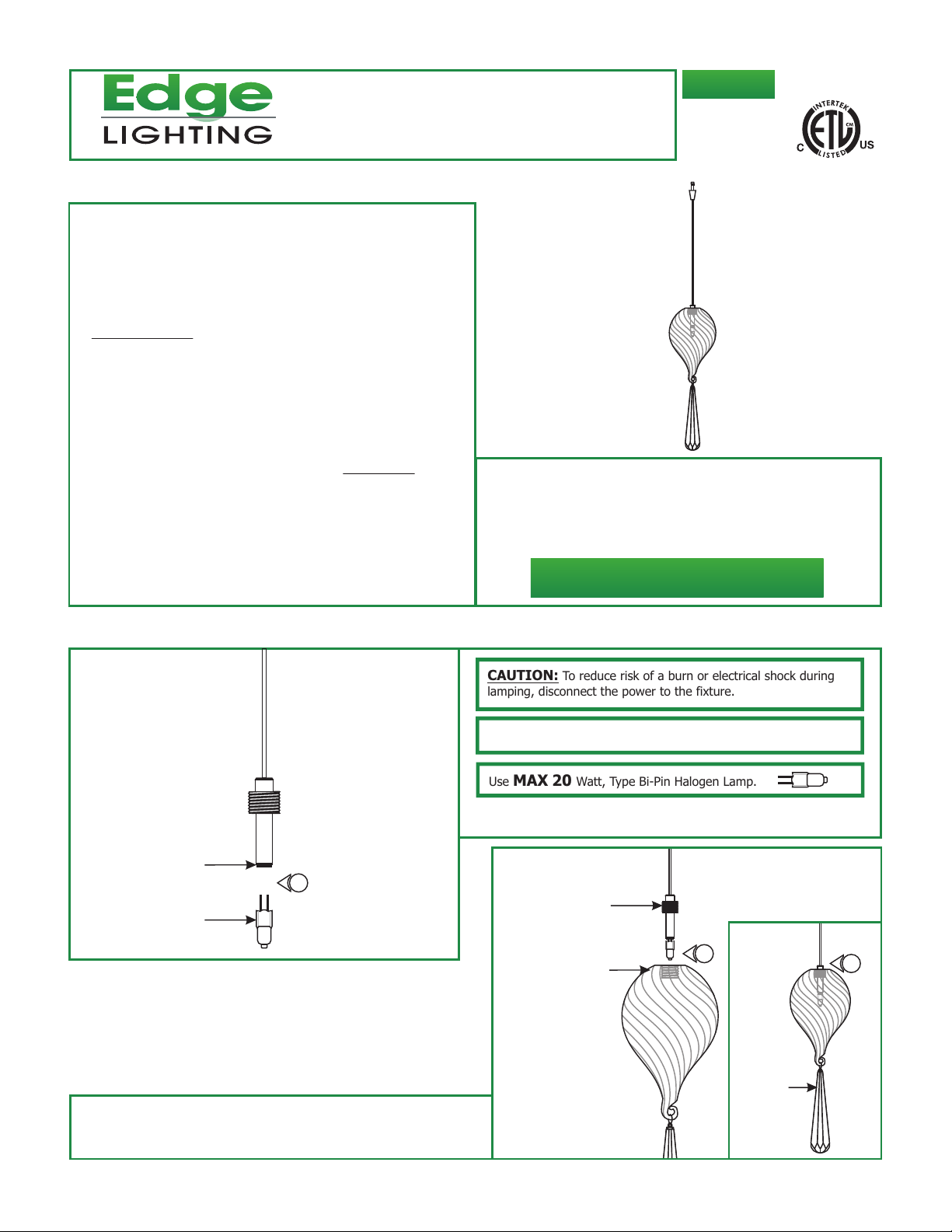
Installation Instructions for Fast Jack Bloom Pendant
IMPORTANT SAFETY INSTRUCTIONS
To reduce the risk of fire, electrical shock, exposure to
excessive UV radiation, or injury to persons:
- Use this fixture indoors only.
- Do not look directly at the lamp while the fixture is on.
- RISK OF FIRE: Use only the type of lamp and maximum
wattage indicated in this instruction manual.
- Never cover the halogen lamp with anything other than a
lamp shield provided by Edge Lighting and never place
flammable material close to the fixture.
- Never turn the fixture on and off by connecting and
disconnecting the halogen lamp.
- Do not touch the fixture head, shade or lamp shield while
the fixture is on. These surfaces may be VERY HOT.
- Do not touch lamp at anytime. Use a soft cloth instead as oil
from skin may damage lamp.
- It is normal for a new halogen lamp to produce minor
smoke when first turned on.
- Do not operate the luminaire with a missing or damaged
shield.
- Turn power off and allow to cool before replacing lamp.
IMPORTANT INFORMATION
- This product is ETL listed for indoor dry locations and
approved to be used at any height above the finished
floor.
SAVE THESE INSTRUCTIONS!
FJ-BLOOM-_
904-FJ-BLOOM-01
Install the Fixture
A
SOCKET
LAMP
CAUTION: To reduce risk of a burn or electrical shock during
lamping, disconnect the power to the fixture.
NOTE: Use only fingers and a soft cloth to install the lamps.
Use MAX 20 Watt, Type Bi-Pin Halogen Lamp.
1: Push the lamp pins completely into the socket holes.
B
1
SOCKET ASSEMBLY
2
GLASS SHADE
2
2: Gently place the glass shade onto the socket assembly.
Rotate the glass shade to secure it to the socket thread until
the top of the socket thread is flush with the glass shade.
CRYSTAL
1
Page 2
C
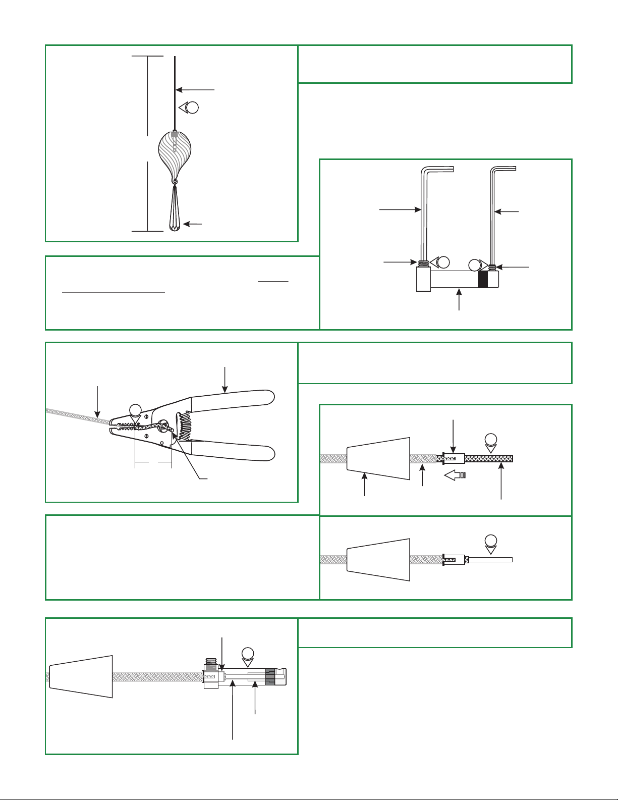
3: Cut the coaxial cable to the desired length (H) with a sharp
cutter. The overall fixture height is measured from the
bottom of the glass shade to the end of the coaxial cable.
COAXIAL CABLE
3
H
D
CRYSTAL
4: Loosen the M4 set screw on base of the coaxial fixture
connector with the 2mm Allen wrench provided. Do not
remove this set screw.
5: Remove the M3 set screw on tip of the connector with the
1.5mm Allen wrench provided.
E
INSULATION
6
1"
WIRE STRIPPER
COAXIAL CABLE
2MM ALLEN
WRENCH
M4 SET SCREW
COAXIAL FIXTURE CONNECTOR
6: Use the #12 gauge hole of the AWG wire strippers to strip
1" of the insulation cover from the end so that the bare
coaxial cable is exposed.
F
INSULATION
CONICAL NIPPLE
4
STRAIN RELIEF TUBE
5
OUTER METAL JACKET
7
1.5MM ALLEN
WRENCH
M3 SET
SCREW
7: Feed the coaxial cable through the conical nipple and flared
side of the strain relief tube. Slide the conical nipple down
the coaxial cable. Slide the strain relief tube against the
insulation.
8: Use the #14 gauge hole of the AWG wire strippers to strip
the outer metal jacket exposed behind the strain relief tube.
G
STRAIN RELIEF TUBE
9
FIXTURE
CONNECTOR
INNER WIRE
8
9: Feed the inner coaxial cable along with strain relief tube
into the coaxial fixture connector.
2
Page 3

H
1.5MM ALLEN WRENCH
M3 SET SCREW
OUTER METAL JACK INNER WIRE
10: Keep feeding the coaxial cable in until the inner wire is
visible in the screw hole of the fixture connector tip.
11: Hold the fixture connector and coaxial cable in place.
Replace and tighten the M3 set screw on fixture connector
tip with the 1.5mm Allen wrench.
11
10
I
12: Make sure the strain relief tube is completely into the
coaxial fixture connector and the slot on the strain relief
tube is not inline with the M4 set screw.
13: Tighten the M4 set screw with the 2mm Allen wrench.
J
14
14
14
14
2MM ALLEN WRENCH
M4 SET SCREW
STRAIN RELIEF TUBE
14: Use fingers to tighten the Fast Jack fixture connector into
the Fast Jack system connector (Monorail, Monorail 2
Circuit, or canopy connector - Refer to the instructions
provided with the system connector or canopy).
15: Refer to the instructions provided with the Monorail 2
Circuit fixture connector to choose Circuit #1 or Circuit #2.
COAXIAL FIXTURE
CONNECTOR
13
12
14
CIRCUIT #1
14
15
CIRCUIT #2
1
2
N
15
1
2
N
3
 Loading...