

Page 1
ALPHA-4-L1-_
ALPHA-7-L1-_
ALPHA-16-L1-_
ALPHA-24-L1-_
© 2014 Edge Lighting. All Rights Reserved.
1718 W. Fullerton Ave
Chicago, IL 60614
Tel: 773-770-1195
Fax: 773-935-5613
www.edgelighting.com
info@edgelighting.com
Installation Instructions for Alpha 4, 7, 16, and 24 LED
IMPORTANT INFORMATION
- Use this fixture indoors only.
- This product is ETL listed for indoor dry locations.
- This product is wall mounted only.
- This product can mount to either a 4" square junction box
with round plaster ring or an octagon junction box.
- This product can be dimmed with a standard low-voltage
electronic dimmer.
- This product must be installed by a qualified electrician.
- Before beginning any electrical work, ensure that
power to the junction box is turned OFF.
SAVE THESE INSTRUCTIONS!
Install the Fixture
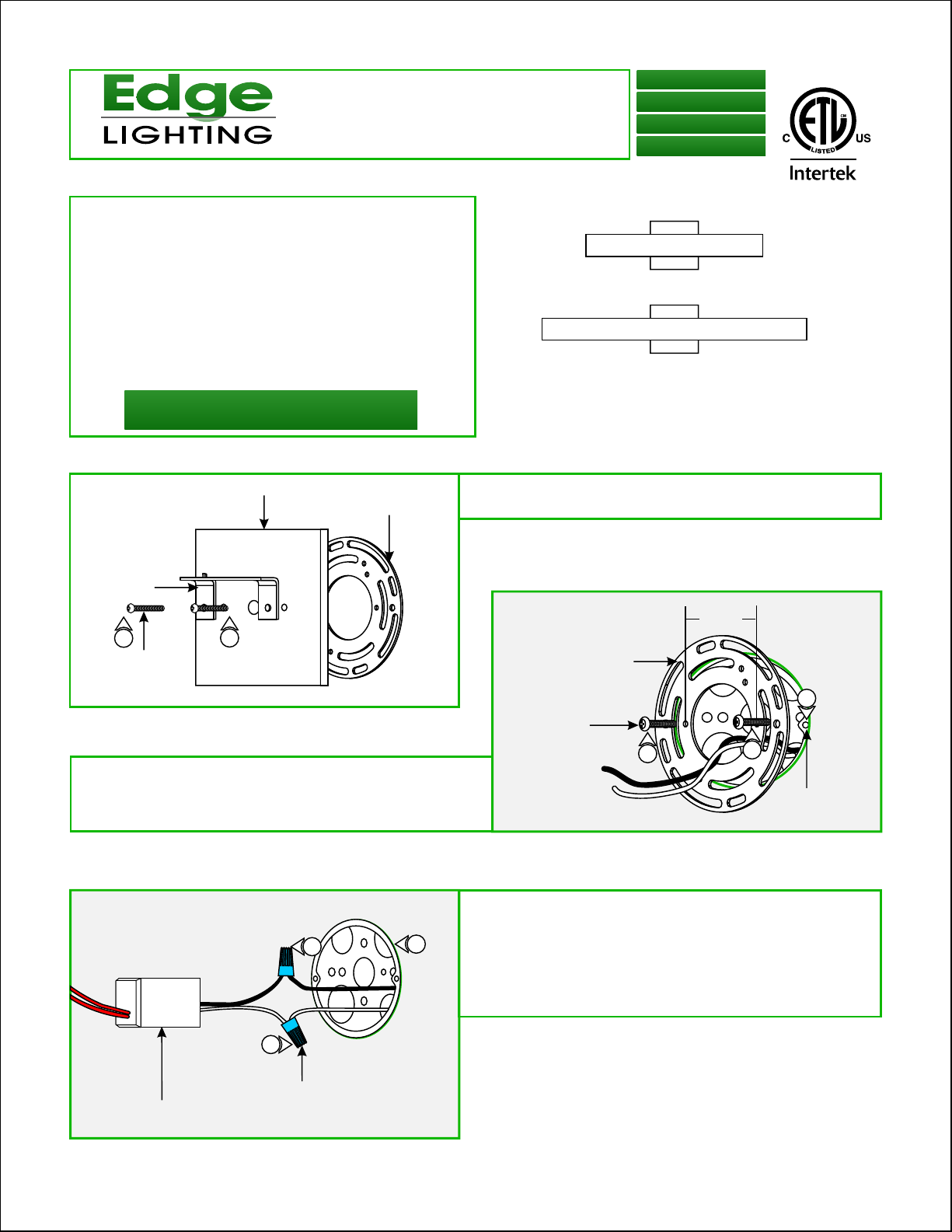
1:
A
CANOPY
UNIVERSAL
CROSSBAR
Loosen the two #8-32 screws from the canopy to remove
the universal crossbar.
904-ALPHA-L1-01
MOUNTING
BRACKET
1
#8-32 SCREW
Mount the universal crossbar to the electrical box holes with
2:
the provided #8-32 screws so that the two inner threaded
holes (spaced 2-1/8" apart) on crossbar are leveled
horizontally.
1
C
4
5
B
UNIVERSAL CROSSBAR
#8-32 SCREW
2
3: Connect the white power supply wire to the neutral power
wire with a wire nut.
4: Connect the black power supply wire to the hot power wire
with a wire nut.
5: Place the power supply and wires inside the electrical box.
2-1/8"
APART
2
2
ELECTRICAL
BOX HOLE
POWER SUPPLY
3
WIRE NUT
1
Page 2

D
MOUNTING
BRACKET
6: Feed the power wires through the canopy center hole.
7: Make sure that the canopy is grounded in accordance with
local electrical codes.
6
#8-32 SCREW
CANOPY
9: Connect each power supply wire to a fixture body wire
(either one) with a wire nut.
F
FIXTURE
BODY HOLE
POWER
WIRES
MOUNTING BRACKET TAB
11
8
8: Secure the canopy to the universal crossbar by tightening
the two #8-32 screws through the mounting bracket holes
into the two inner threaded crossbar holes.
E
9
9
10: Place all wires and wire nut connections behind the fixture
body.
11: Place the left fixture body hole onto the mounting bracket
tab.
10
12: Secure the right fixture body hole with the flat head
Phillips screw provided.
H
SPRING CLIP
13
GLASS COVER
13
G
CANOPY
13: Loosen the screws on the spring clips (Do Not Remove)
to insert the glass cover under the clips. Slightly tighten the
spring clip screws to secure the glass cover in place.
12
FIXTURE BODY
FLAT HEAD
PHILLIPS SCREW
2
 Loading...