

Edge Lighting Alpha User Manual
© 2009 Edge Lighting. All Rights Reserved.
1718 W. Fullerton Ave
Chicago, IL 60614
Tel: 773-770-1195
Fax: 773-935-5613
www.edgelighting.com
info@edgelighting.com
ALPHA-4-H1-_
M2-IND-_
Installation Instructions for Alpha 4 (Halogen Version)
IMPORTANT SAFETY INSTRUCTIONS
To reduce the risk of fire, electrical shock, exposure to
excessive UV radiation, or injury to persons:
- Use this fixture indoors only.
- Do not look directly at the lamp while the fixture is on.
- RISK OF FIRE: Use only the type of lamp and maximum
wattage indicated in this instruction manual.
- Never cover the halogen lamp with anything other than a
lamp shield provided by Edge Lighting and never place
flammable material close to the fixture.
- Never turn the fixture on and off by connecting and
disconnecting the halogen lamp.
- Do not touch the fixture head, shade or lamp shield while
the fixture is on. These surfaces may be VERY HOT.
- Do not touch lamp at anytime. Use a soft cloth instead as oil
from skin may damage lamp.
- It is normal for a new halogen lamp to produce minor
smoke when first turned on.
- Turn power off and allow to cool before replacing lamp.
IMPORTANT INFORMATION
- This product is ETL listed for indoor dry locations.
- This product is wall mounted only.
- This product can mount to either a 4" square electrical box
with round plaster ring or an octagon electrical box.
- This product can be dimmed with a standard incandescent
dimmer.
SAVE THESE INSTRUCTIONS!
904-ALPHA-4-H1-04
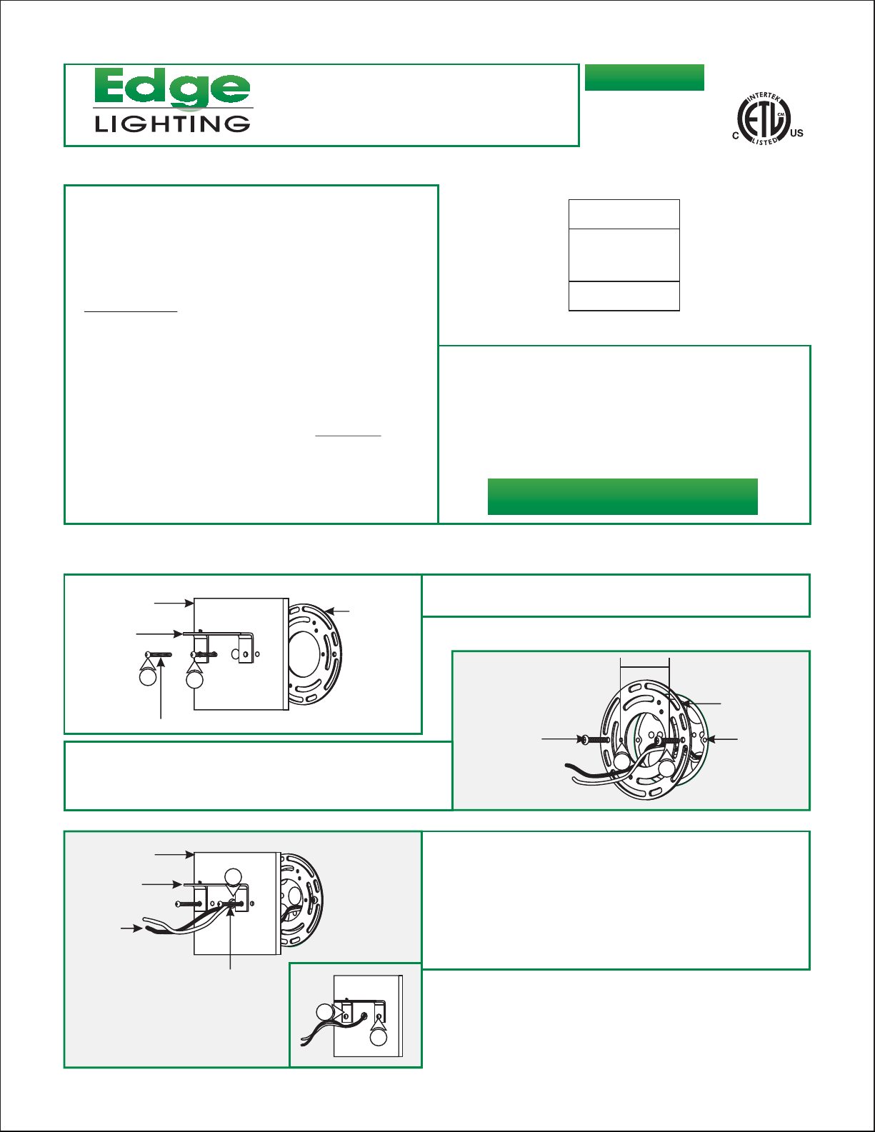
Install the Fixture
A
CANOPY
MOUNTING
BRACKET
1
#8-32 SCREW
2:
Mount the universal crossbar to the electrical box holes with
the provided #8-32 screws so that the two inner threaded
holes (spaced 2-1/8" apart) on crossbar are leveled
horizontally.
C
CANOPY
MOUNTING
BRACKET
POWER
WIRES
1
3
UNIVERSAL
CROSSBAR
1:
Loosen the two #8-32 screws from the canopy to remove
the universal crossbar.
B
#8-32 SCREW
3: Feed the power wires through the canopy center hole.
4: Make sure that the canopy is grounded in accordance with
local electrical codes.
5: Secure the canopy to the universal crossbar by tightening
the two #8-32 screws through the mounting bracket holes
into the two inner threaded crossbar holes.
2-1/8" APART
UNIVERSAL
CROSSBAR
ELECTRICAL
BOX HOLE
2
2
#8-32 SCREW
5
5
1
D
6: Connect the white fixture wire to the neutral power wire with
a wire nut.
6
7
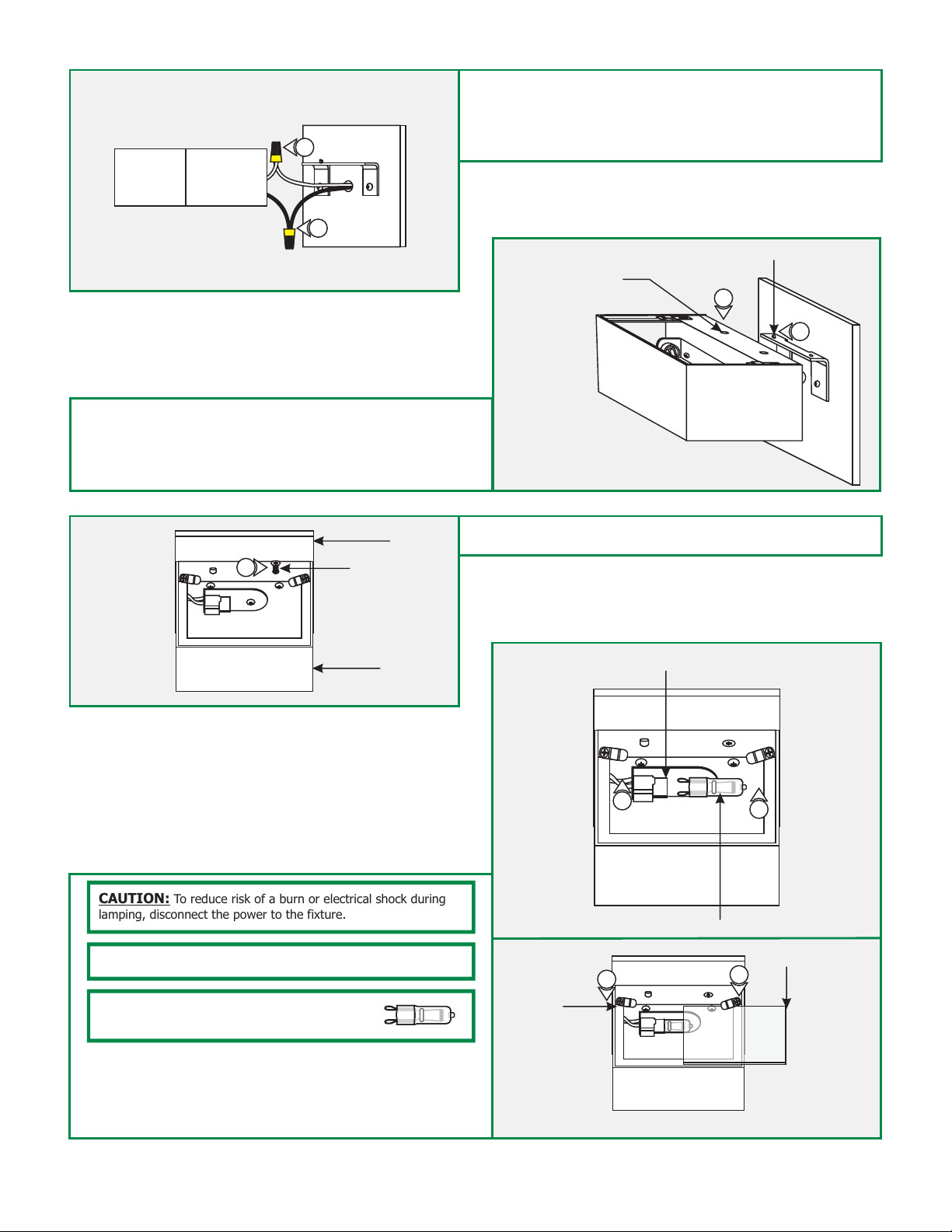
8: Place all wires and wire nut connections behind the fixture
body.
9: Place the left fixture body hole onto the mounting bracket
tab.
F
10
CANOPY
FLAT HEAD
PHILLIPS SCREW
7: Connect the black fixture wire to the hot power wire with a
wire nut.
E
FIXTURE BODY HOLE
10: Secure the other fixture body hole with the flat head
Phillips screw provided.
MOUNTING BRACKET TAB
8
9
FIXTURE
BODY
CAUTION: To reduce risk of a burn or electrical shock during
lamping, disconnect the power to the fixture.
NOTE: Use only fingers and a soft cloth to install the lamps.
Use MAX 60 Watt Type T4, G9 Base, Bi-Pin
Halogen Lamp.
11: Push the lamp pins completely into the socket holes.
12: Loosen the screws on the spring clips to insert the glass
cover under the clips. Slightly tighten the spring clip screws
to secure glass cover in place.
G
SPRING
CLIP
12
11
SOCKET
LAMP
11
GLASS COVER
12
2
 Loading...