

Page 1

© 2011 Edge Lighting. All Rights Reserved.
1718 W. Fullerton Ave
Chicago, IL 60614
Tel: 773-770-1195
Fax: 773-935-5613
www.edgelighting.com
info@edgelighting.com
M2P-4RD-SL-_
Installation Instructions for Monorail 2 Circuit Sloped 4" Round
Extended Single Power Feed Canopy
IMPORTANT INFORMATION
- This product is ETL listed for indoor dry locations.
- This product can be installed to a 4" electrical box with
round plaster ring, or to an octagon electrical box.
- Minimum electrical box volume must be 6 cubic inches
(98 cubic centimeters).
- This product should be installed by a qualified electrician.
SAVE THESE INSTRUCTIONS!
Install the Canopy
904-M2P-4RD-SL-03
A
SIDE WIRE
COM
4
TOP CONTACT
WIRE
HOT 2
3
HOT 1
2
MIDDLE
CONTACT WIRE
NOTE: If necessary adjustments can be made to the height of the
power feed rod by following step "Shortening the Power Feed Rod
Height" on page 3.
NOTE: Use the universal round crossbar (provided) if the electrical
box holes are not spaced 2-3/4" apart.
NOTE: The low voltage wires should be present in the electrical
box. Refer to the instructions provided with the remote
transformer to install the transformer and the low voltage wires
before proceeding with the steps below.
1: Turn the power to electrical box off.
2: Connect the top contact wire (black wire) to the low voltage
wire marked "HOT 1" with a wire nut.
3: Connect the middle contact wire (coming out of the
cylindrical connector) to the low voltage marked "HOT 2"
with a wire nut.
4: Connect the remaining side wire to the low voltage wire
marked "COM" with a wire nut.
B
5
CYLINDRICAL
CONNECTOR
5: Place all wires inside the electrical box.
6: Secure the power feed canopy to the electrical box by
tightening the two provided #8-32 screws with the 3/32
Allen wrench.
#8-32
SCREW
3/32 ALLEN
WRENCH
6
6
Page 2
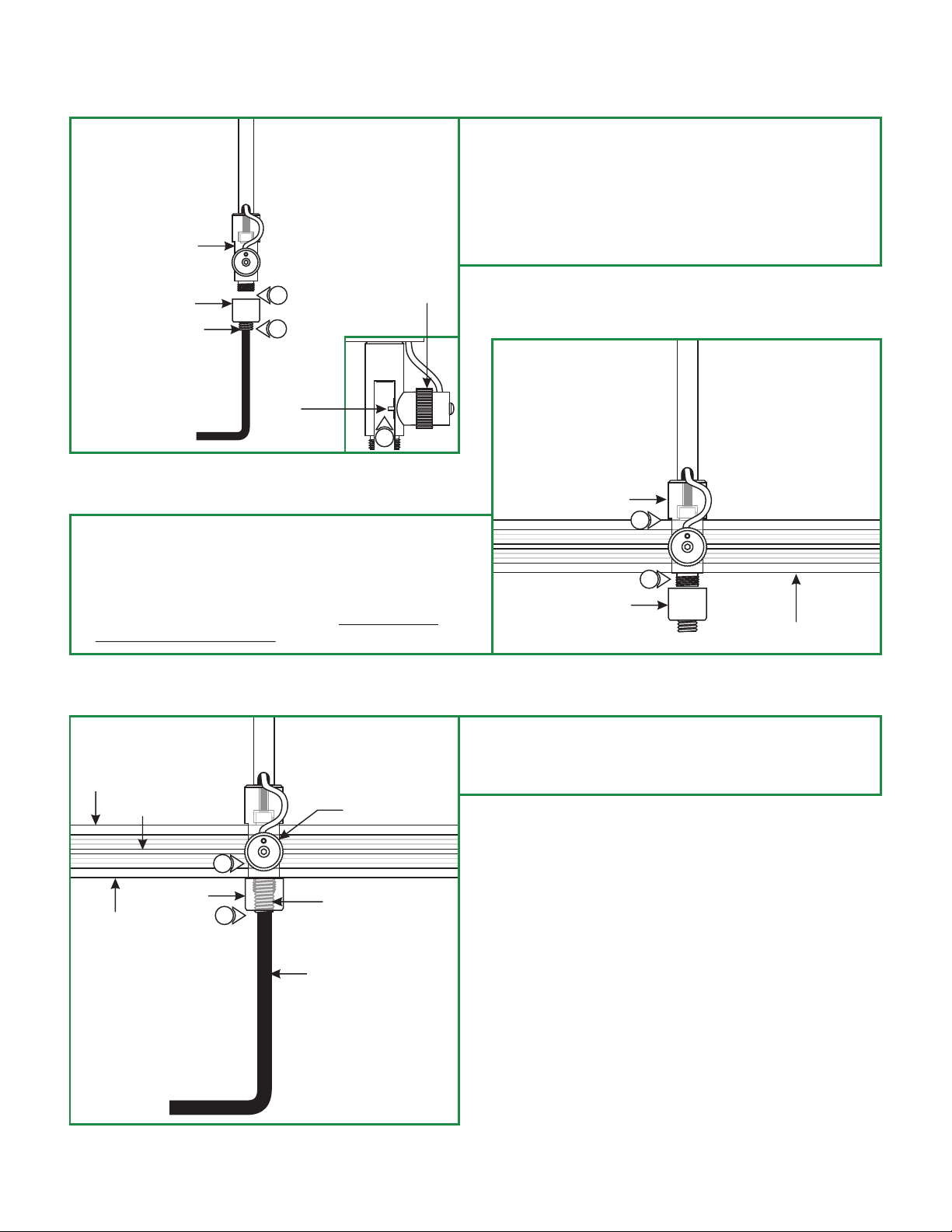
Install the Monorail 2 Circuit to the Power Feed Canopy
C
POWER HOUSING
CAP
3/8-24 SETSCREW
4: Place the a section of Monorail 2 Circuit into the power
housing. Make sure that the Monorail 2 Circuit is supported
by the sloped standoffs. Refer to the instructions provided
with the standoffs.
5: Tighten the cap to the power housing. Make sure the
cap is not cross threaded.
sloped
1
2
MIDDLE
CONTACT
KNURLED
NUT
3
1: Unscrew the cap from the power housing.
2: Slightly loosen the 3/8-24 set screw on the cap with the
3/16 Allen wrench provided, (DO NOT REMOVE IT).
3: Slightly loosen the knurled nut on the power housing so that
the middle contact moves back and clears the power housing
opening.
D
POWER HOUSING
4
5
CAP
MONORAIL 2 CIRCUIT
E
HOT 1
CAM
HOT 2
CAP
6: Tighten the 3/8-24 set screw on the cap with the 3/16
Allen wrench for proper power connection.
7: Tighten the knurled nut for proper power connection.
KNURLED NUT
7
3/8-24 SET SCREW
6
3/16 ALLEN WRENCH
2
Page 3

Shortening the Power Feed Rod Height
F
BUSHING
2
POWER FEED ROD
3: From the end of the power feed rod mark the rod to the
amount that needs to be shorten. For example to resize 24"
standoff to 17", mark 7" from the end of the power feed rod.
1
2MM ALLEN
WRENCH
M4 SET SCREW
1: Remove the wire nut from the center wire.
2: Loosen (DO NOT REMOVE) the bottom M3 set screw on
the bushing and carefully pull out the power feed rod along
with the center wire.
G
3
POWER FEED ROD
H
PIPE CUTTER
4
POWER FEED ROD
POWER HOUSING
POWER FEED CAP
5: Feed the center wire through the bushing inserting the
power feed rod completely inside the bushing. Tighten
the bottom M3 set screw with the 1.5mm Allen wrench.
4: Use a pipe cutter to cut out the excess rod.
I
BUSHING
5
POWER FEED ROD
M4 SET SCREW
2MM ALLEN
WRENCH
6: Follow the "Install the Canopy" steps on page 1.
3
 Loading...