

Page 1

OAP6626A
Powered by Accton
Dual-Band Outdoor
Access Point / Bridge
User Guide
www.edge-core.com
Page 2

Page 3

User Guide
Dual-Band Outdoor Access Point/Bridge
IEEE 802.11a/b/g Access Point / Bridge
With External Antenna Options and Integrated High-Gain Antenna
Page 4

OAP6626A-38
E022006-R01
Page 5

Compliances
Federal Communication Commission Interference Statement
This equipment has been tested and found to comply with the limits for a Class B digital
device, pursuant to Part 15 of the FCC Rules. These limits are designed to provide
reasonable protection against harmful interference in a residential installation. This
equipment generates, uses and can radiate radio frequency energy and, if not installed
and used in accordance with the instructions, may cause harmful interference to radio
communications. However, there is no guarantee that interference will not occur in a
particular installation. If this equipment does cause harmful interference to radio or
television reception, which can be determined by turning the equipment off and on, the
user is encouraged to try to correct the interference by one of the following measures:
• Reorient or relocate the receiving antenna
• Increase the separation between the equipment and receiver
• Connect the equipment into an outlet on a circuit different from that to which the receiver
is connected
• Consult the dealer or an experienced radio/TV technician for help
Warnings: 1.Wear an anti-static wrist strap or take other suitable measures to prevent
2.When connecting this device to a power outlet, connect the field ground
IMPORTANT NOTE: FCC Radiation Exposure Statement
This equipment complies with FCC radiation exposure limits set forth for an uncontrolled
environment. This equipment should be installed and operated with a minimum distance
of 20 centimeters (8 inches) between the radiator and your body. This transmitter must
not be co-located or operating in conjunction with any other antenna or transmitter.
electrostatic discharge when handling this equipment.
lead on the tri-pole power plug to a valid earth ground line to prevent
electrical hazards.
Wireless 5 GHz Band Statement:
As the access point can operate in the 5150-5250 MHz frequency band it is limited by the
FCC, Industry Canada and some other countries to indoor use only so as to reduce the
potential for harmful interference to co-channel Mobile Satellite systems.
High power radars are allocated as primary users (meaning they have priority) of the
5250-5350 MHz and 5650-5850 MHz bands. These radars could cause interference and/
or damage to the access point.
i
Page 6

EC Conformance Declaration
Marking by the above symbol indicates compliance with the Essential Requirements of
the R&TTE Directive of the European Union (1999/5/EC). This equipment meets the
following conformance standards:
• EN 60950 (IEC 60950) - Product Safety
• EN 301 893 - Technical requirements for 5 GHz radio equipment
• EN 300 328 - Technical requirements for 2.4 GHz radio equipment
• EN 301 489-1 / EN 301 489-17 - EMC requirements for radio equipment
0560
Countries of Operation & Conditions of Use in the European
Community
This device is intended to be operated in all countries of the European Community.
Requirements for indoor vs. outdoor operation, license requirements and allowed
channels of operation apply in some countries as described below:
Note: The user must use the configuration utility provided with this product to ensure the
channels of operation are in conformance with the spectrum usage rules for
European Community countries as described below.
• This device requires that the user or installer properly enter the current country of
operation in the command line interface as described in the user guide, before operating
this device.
• This device will automatically limit the allowable channels determined by the current
country of operation. Incorrectly entering the country of operation may result in illegal
operation and may cause harmful interference to other system. The user is obligated to
ensure the device is operating according to the channel limitations, indoor/outdoor
restrictions and license requirements for each European Community country as
described in this document.
• This device employs a radar detection feature required for European Community
operation in the 5 GHz band. This feature is automatically enabled when the country of
operation is correctly configured for any European Community country. The presence of
nearby radar operation may result in temporary interruption of operation of this device.
The radar detection feature will automatically restart operation on a channel free of
radar.
• The 5 GHz Turbo Mode feature is not allowed for operation in any European Community
country. The current setting for this feature is found in the 5 GHz 802.11a Radio Settings
Window as described in the user guide.
• The 5 GHz radio's Auto Channel Select setting described in the user guide must always
remain enabled to ensure that automatic 5 GHz channel selection complies with
European requirements. The current setting for this feature is found in the 5 GHz
802.11a Radio Settings Window as described in the user guide.
ii
Page 7

• This device may be operated indoors or outdoors in all countries of the European
Community using the 2.4 GHz band: Channels 1 - 13, except where noted below.
- In Italy the end-user must apply for a license from the national spectrum authority to
operate this device outdoors.
- In Belgium outdoor operation is only permitted using the 2.46 - 2.4835 GHz band:
Channel 13.
- In France outdoor operation is only permitted using the 2.4 - 2.454 GHz band:
Channels 1 - 7
Operation Using 5 GHz Channels in the European Community
The user/installer must use the provided configuration utility to check the current channel
of operation and make necessary configuration changes to ensure operation occurs in
conformance with European National spectrum usage laws as described below and
elsewhere in this document.
Allowed 5GHz Channels in Each European Community Country
Allowed Frequency Bands Allowed Channel Numbers Countries
5.15 - 5.25 GHz* 36, 40, 44, 48 Austria, Belgium
5.15 - 5.35 GHz* 36, 40, 44, 48, 52, 56, 60, 64 France, Switzerland,
Liechtenstein
5.15 - 5.35* & 5.470 - 5.725
GHz
5 GHz Operation Not Allowed None Greece
* Outdoor operation is not allowed using 5.15-5.35 GHz bands (Channels 36 - 64).
Channels 36 - 64 are currently not available for use.
36, 40, 44, 48, 52, 56, 60, 64,
100, 104, 108, 112, 116, 120,
124, 128, 132, 136, 140
Denmark, Finland,
Germany, Iceland,
Ireland, Italy,
Luxembourg,
Netherlands, Norway,
Portugal, Spain,
Sweden, U.K.
iii
Page 8

Declaration of Conformity in Languages of the European
Community
English Hereby, Edgecore, declares that this Radio LAN device is in compliance
Finnish Valmistaja Edgecore vakuuttaa täten että Radio LAN device tyyppinen
Dutch Hierbij verklaart Edgecore dat het toestel Radio LAN device in overeen-
French Par la présente Edgecore déclare que l'appareil Radio LAN device est
Swedish Härmed intygar Edgecore att denna Radio LAN device står I överens-
Danish Undertegnede Edgecore erklærer herved, at følgende udstyr Radio LAN
German Hiermit erklärt Edgecore, dass sich dieser/diese/dieses Radio LAN de-
Greek με την παρουσα E
Italian Con la presente Edgecore dichiara che questo Radio LAN device è con-
Spanish Por medio de la presente Edgecore declara que el Radio LAN device
Portuguese Edgecore declara que este Radio LAN device está conforme com os req-
with the essential requirements and other relevant provisions of Directive
1999/5/EC.
laite on direktiivin 1999/5/EY oleellisten vaatimusten ja sitä koskevien
direktiivin muiden ehtojen mukainen.
stemming is met de essentiële eisen en de andere relevante bepalingen
van richtlijn 1999/5/EG
Bij deze Edgecore dat deze Radio LAN device voldoet aan de essentiële
eisen en aan de overige relevante bepalingen van Richtlijn 1999/5/EC.
conforme aux exigences essentielles et aux autres dispositions pertinentes de la directive 1999/5/CE
stämmelse med de väsentliga egenskapskrav och övriga relevanta bestämmelser som framgår av direktiv 1999/5/EG.
device overholder de væsentlige krav og øvrige relevante krav i direktiv
1999/5/EF
vice in Übereinstimmung mit den grundlegenden Anforderungen und den
anderen relevanten Vorschriften der Richtlinie 1999/5/EG befindet". (BMWi)
Hiermit erklärt Edgecore die Übereinstimmung des Gerätes Radio LAN
device mit den grundlegenden Anforderungen und den anderen relevanten Festlegungen der Richtlinie 1999/5/EG. (Wien)
DGECORE δηλωνει οτι radio LAN device συμμορφωνεται
προσ τισ ουσιωδεισ απαιτησεισ και τισ λοιπεσ σΧετικεσ διαταξεισ τησ
οδηγιασ 1999/5/εκ
forme ai requisiti essenziali ed alle altre disposizioni pertinenti stabilite
dalla direttiva 1999/5/CE.
cumple con los requisitos esenciales y cualesquiera otras disposiciones
aplicables o exigibles de la Directiva 1999/5/CE
uisitos essenciais e outras disposições da Directiva 1999/5/CE.
iv
Page 9

Safety Compliance
Power Cord Safety
Please read the following safety information carefully before installing the device:
Warning:Installation and removal of the unit must be carried out by qualified personnel
• The unit must be connected to an earthed (grounded) outlet to comply with international
• Do not connect the unit to an A.C. outlet (power supply) without an earth (ground)
• The appliance coupler (the connector to the unit and not the wall plug) must have a
• The socket outlet must be near to the unit and easily accessible. You can only remove
• This unit operates under SELV (Safety Extra Low Voltage) conditions according to IEC
France and Peru only
This unit cannot be powered from IT
must be powered by 230 V (2P+T) via an isolation transformer ratio 1:1, with the
secondary connection point labelled Neutral, connected directly to earth (ground).
†
Impédance à la terre
Important! Before making connections, make sure you have the correct cord set. Check
it (read the label on the cable) against the following:
only.
safety standards.
connection.
configuration for mating with an EN 60320/IEC 320 appliance inlet.
power from the unit by disconnecting the power cord from the outlet.
60950. The conditions are only maintained if the equipment to which it is connected also
operates under SELV conditions.
†
supplies. If your supplies are of IT type, this unit
Power Cord Set
U.S.A. and
Canada
The cord set must be UL-approved and CSA certified.
The minimum specifications for the flexible cord are:
- No. 18 AWG - not longer than 2 meters, or 16 AWG.
- Type SV or SJ
- 3-conductor
The cord set must have a rated current capacity of at least 10 A
The attachment plug must be an earth-grounding type with
NEMA 5-15P (15 A, 125 V) or NEMA 6-15P (15 A, 250 V)
configuration.
Denmark The supply plug must comply with Section 107-2-D1, Standard
DK2-1a or DK2-5a.
Switzerland The supply plug must comply with SEV/ASE 1011.
U.K. The supply plug must comply with BS1363 (3-pin 13 A) and be
fitted with a 5 A fuse which complies with BS1362.
The mains cord must be <HAR> or <BASEC> marked and be of
type HO3VVF3GO.75 (minimum).
v
Page 10

Power Cord Set
Europe The supply plug must comply with CEE7/7 (“SCHUKO”).
The mains cord must be <HAR> or <BASEC> marked and be of
type HO3VVF3GO.75 (minimum).
IEC-320 receptacle.
Veuillez lire à fond l'information de la sécurité suivante avant d'installer l’appareil:
AVERTISSEMENT: L’installation et la dépose de ce groupe doivent être confiés à un
personnel qualifié.
• Ne branchez pas votre appareil sur une prise secteur (alimentation électrique) lorsqu'il
n'y a pas de connexion de mise à la terre (mise à la masse).
• Vous devez raccorder ce groupe à une sortie mise à la terre (mise à la masse) afin de
respecter les normes internationales de sécurité.
• Le coupleur d’appareil (le connecteur du groupe et non pas la prise murale) doit
respecter une configuration qui permet un branchement sur une entrée d’appareil EN
60320/IEC 320.
• La prise secteur doit se trouver à proximité de l’appareil et son accès doit être facile.
Vous ne pouvez mettre l’appareil hors circuit qu’en débranchant son cordon électrique
au niveau de cette prise.
• L’appareil fonctionne à une tension extrêmement basse de sécurité qui est conforme à
la norme IEC 60950. Ces conditions ne sont maintenues que si l’équipement auquel il
est raccordé fonctionne dans les mêmes conditions.
France et Pérou uniquement:
Ce groupe ne peut pas être alimenté par un dispositif à impédance à la terre. Si vos
alimentations sont du type impédance à la terre, ce groupe doit être alimenté par une
tension de 230 V (2 P+T) par le biais d’un transformateur d’isolement à rapport 1:1, avec
un point secondaire de connexion portant l’appellation Neutre et avec raccordement
direct à la terre (masse).
Cordon électrique - Il doit être agréé dans le pays d’utilisation
Etats-Unis et
Canada:
Danemark: La prise mâle d’alimentation doit respecter la section 107-2 D1
vi
Le cordon doit avoir reçu l’homologation des UL et un certificat
de la CSA.
Les spe'cifications minimales pour un cable flexible sont AWG
No. 18, ouAWG No. 16 pour un cable de longueur infe'rieure a`
2 me'tres.
- type SV ou SJ
- 3 conducteurs
Le cordon doit être en mesure d’acheminer un courant nominal
d’au moins 10 A.
La prise femelle de branchement doit être du type à mise à la
terre (mise à la masse) et respecter la configuration NEMA
5-15P (15 A, 125 V) ou NEMA 6-15P (15 A, 250 V).
de la norme DK2 1a ou DK2 5a.
Page 11

Cordon électrique - Il doit être agréé dans le pays d’utilisation
Suisse: La prise mâle d’alimentation doit respecter la norme SEV/ASE
Europe La prise secteur doit être conforme aux normes CEE 7/7
Bitte unbedingt vor dem Einbauen des Geräts die folgenden
Sicherheitsanweisungen durchlesen
WARNUNG: Die Installation und der Ausbau des Geräts darf nur durch Fachpersonal
erfolgen.
• Das Gerät sollte nicht an eine ungeerdete Wechselstromsteckdose angeschlossen
werden.
• Das Gerät muß an eine geerdete Steckdose angeschlossen werden, welche die
internationalen Sicherheitsnormen erfüllt.
• Der Gerätestecker (der Anschluß an das Gerät, nicht der Wandsteckdosenstecker) muß
einen gemäß EN 60320/IEC 320 konfigurierten Geräteeingang haben.
• Die Netzsteckdose muß in der Nähe des Geräts und leicht zugänglich sein. Die
Stromversorgung des Geräts kann nur durch Herausziehen des Gerätenetzkabels aus
der Netzsteckdose unterbrochen werden.
• Der Betrieb dieses Geräts erfolgt unter den SELV-Bedingungen
(Sicherheitskleinstspannung) gemäß IEC 60950. Diese Bedingungen sind nur gegeben,
wenn auch die an das Gerät angeschlossenen Geräte unter SELV-Bedingungen
betrieben werden.
1011.
(“SCHUKO”)
LE cordon secteur doit porter la mention <HAR> ou <BASEC> et
doit être de type HO3VVF3GO.75 (minimum).
(Germany):
vii
Page 12

Stromkabel. Dies muss von dem Land, in dem es benutzt wird geprüft werden:
U.S.A und Canada Der Cord muß das UL gepruft und war das CSA beglaubigt.
Das Minimum spezifikation fur der Cord sind:
- Nu. 18 AWG - nicht mehr als 2 meter, oder 16 AWG.
- Der typ SV oder SJ
- 3-Leiter
Der Cord muß haben eine strombelastbarkeit aus wenigstens
10 A
Dieser Stromstecker muß hat einer erdschluss mit der typ
NEMA 5-15P (15A, 125V) oder NEMA 6-15P (15A, 250V)
konfiguration.
Danemark Dieser Stromstecker muß die ebene 107-2-D1, der standard
Schweiz Dieser Stromstecker muß die SEV/ASE 1011Bestimmungen
Europe Das Netzkabel muß vom Typ HO3VVF3GO.75
DK2-1a oder DK2-5a Bestimmungen einhalten.
einhalten.
(Mindestanforderung) sein und die Aufschrift <HAR> oder
<BASEC> tragen.
Der Netzstecker muß die Norm CEE 7/7 erfüllen (”SCHUKO”).
viii
Page 13

Contents
Chapter 1: Introduction 1-1
Package Checklist 1-2
Hardware Description 1-3
Integrated High-Gain Antenna 1-3
External Antenna Options 1-3
Ethernet Port 1-4
Power Injector Module 1-4
Receive Signal Strength Indicator (RSSI) BNC Connector 1-5
Grounding Point 1-5
Wall- and Pole-Mounting Bracket Kits 1-5
System Configuration 1-6
Features and Benefits 1-6
System Defaults 1-7
Chapter 2: Network Configuration 2-1
Access Point Topologies 2-1
Ad Hoc Wireless LAN (no Access Point or Bridge) 2-1
Infrastructure Wireless LAN 2-2
Infrastructure Wireless LAN for Roaming Wireless PCs 2-3
Bridge Link Topologies 2-4
Point-to-Point Configuration 2-4
Point-to-Multipoint Configuration 2-4
Chapter 3: Bridge Link Planning 3-1
Data Rates 3-1
Radio Path Planning 3-2
Antenna Height 3-4
Antenna Position and Orientation 3-5
Radio Interference 3-6
Weather Conditions 3-6
Ethernet Cabling 3-7
Grounding 3-7
Chapter 4: Hardware Installation 4-1
Testing Basic Link Operation 4-1
Mount the Unit 4-1
Using the Pole-Mounting Bracket 4-1
Using the Wall-Mounting Bracket 4-4
Connect External Antennas 4-5
Connect Cables to the Unit 4-6
Connect the Power Injector 4-7
ix
Page 14

Contents
Align Antennas 4-8
Appendix A: Troubleshooting A-1
Appendix B: Specifications B-1
General Specifications B-1
Antenna Specifications B-3
17 dBi Integrated Panel B-3
8 dBi Omnidirectional (2.4 GHz) B-4
8 dBi Omnidirectional (5 GHz) B-6
13.5 dBi 120-Degree Sector B-7
16.5 dBi 60-Degree Sector B-9
23 dBi High-Gain Panel B-11
Appendix C: Cables and Pinouts C-1
Twisted-Pair Cable Assignments C-1
10/100BASE-TX Pin Assignments C-2
Straight-Through Wiring C-2
Crossover Wiring C-3
8-Pin DIN Connector Pinout C-3
8-Pin DIN to RJ-45 Cable Wiring C-4
Glossary
Index
x
Page 15

Chapter 1: Introduction
The Dual-band Outdoor Access Point / Bridge system provides point-to-point or
point-to-multipoint bridge links between remote Ethernet LANs, and wireless access
point services for clients in the local LAN area.
• OAP6626A – Includes an integrated high-gain antenna for the 802.11a radio and
can be configured to operate as a “Master” or “Slave” bridge in point-to-multipoint
configurations, or provide a high-speed point-to-point wireless link between two
sites that can be up to 15.4 km (9.6 miles) apart. Up to two 5 GHz and two 2.4 GHz
antennas con be connected to the uinit. The 802.11b/g radio requires an external
antenna option. It supports wireless bridge connections to as many as 16
OAP6626A units configured as slaves.
The unit is housed in a weatherproof enclosure for mounting outdoors and includes
its own brackets for attaching to a wall, pole, radio mast, or tower structure. It is
powered through its Ethernet cable connection from a power injector module that is
installed indoors.
The wireless bridge system offers a fast, reliable, and cost-effective solution for
connectivity between remote Ethernet wired LANs or to provide Internet access to
an isolated site. The system is also easy to install and operate, ideal for situations
where a wired link may be difficult or expensive to deploy. The wireless bridge
connection provides data rates of up to 108 Mbps.
In addition, both wireless bridge models offer full network management capabilities
through an easy-to-use web interface, a command-line interface, and support for
Simple Network Management Protocol (SNMP) tools.
Radio Characteristics – The IEEE 802.11a and 802.11g standards use a radio
modulation technique known as Orthogonal Frequency Division Multiplexing
(OFDM), and a shared collision domain (CSMA/CA). The 802.11a standard operates
in the 5 GHz Unlicensed National Information Infrastructure (UNII) band, and the
802.11g standard in the 2.4 GHz band.
IEEE 802.11g includes backward compatibility with the IEEE 802.11b standard.
IEEE 802.11b also operates at 2.4 GHz, but uses Direct Sequence Spread
Spectrum (DSSS) and Complementary Code Keying (CCK) modulation technology
to achieve a communication rate of up to 11 Mbps.
The wireless bridge provides a 54 Mbps half-duplex connection for each active
channel (up to 108 Mbps in turbo mode on the 802.11a interface).
1-1
Page 16

Introduction
1
Package Checklist
The Dual-band Outdoor Access Point / Bridge package includes:
• One Dual-band Outdoor Access Point / Bridge (OAP6626A)
• One Category 5 network cable, length 164 ft (50 m)
• One power injector module and power cord (2.15 m)
• One POE powercore cable (? m)
• One RS-232 console cable (? m)
• Outdoor mounting bracket kit
• This User Guide
• Owners registration card
Inform your dealer if there are any incorrect, missing or damaged parts. If possible,
retain the carton, including the original packing materials. Use them again to repack
the product in case there is a need to return it.
1-2
Page 17
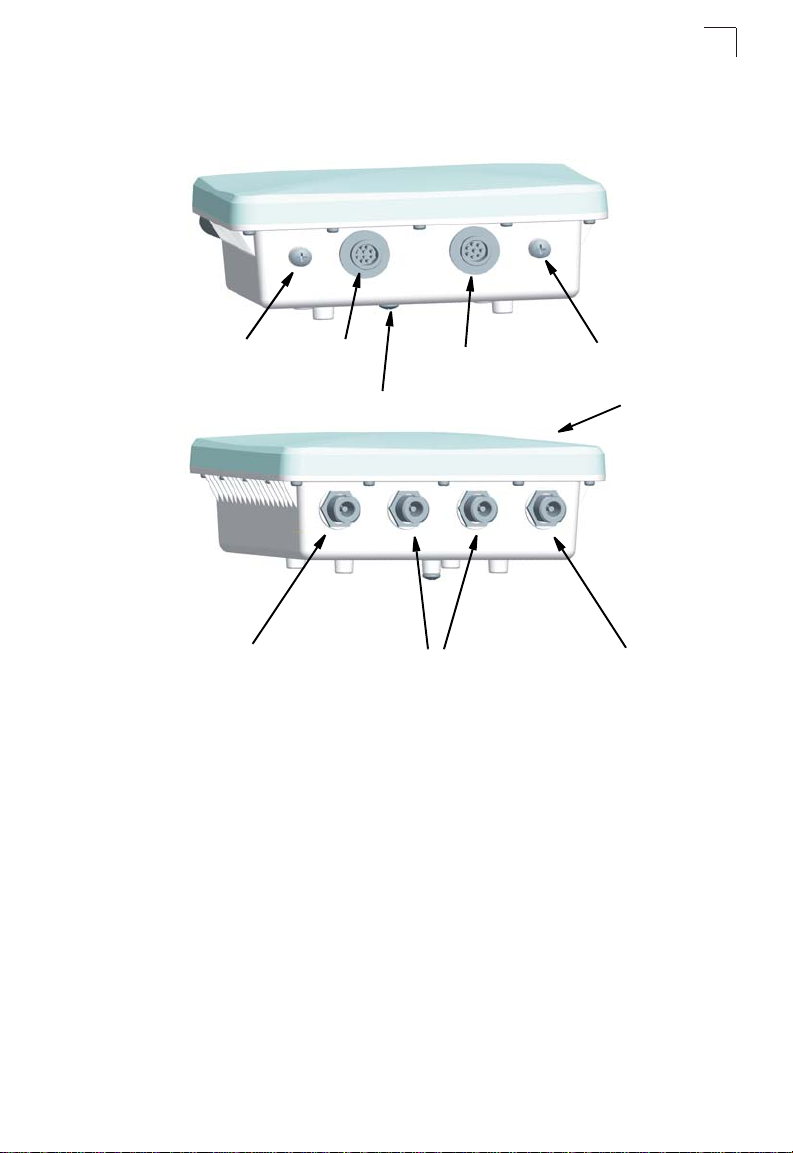
Hardware Description
Bottom View
Hardware Description
1
Top View
Console Port
N-Type External
Antenna Connector
(2.4 GHz)
Console Port
Connector
Grounding Point
POE Connector
N-Type External
Antenna Connectors
(2.4 GHz)
Watertight Test
Point
Integrated Antenna
N-Type External
Antenna Connector
(2.4 GHz)
Integrated High-Gain Antenna
The OAP6626A wireless bridge includes an integrated high-gain (17 dBi) flat-panel
antenna for 5 GHz operation. The antenna can provide a direct line-of-sight link up
to 15.4 km (9.6 miles) with a 6 Mbps data rate.
External Antenna Options
The unit provides various external antenna options for both 5 GHz and 2.4 GHz
operation. In a point-to-multipoint configuration, an external high-gain
omnidirectional, sector, or high-gain panel antenna can be attached to communicate
with bridges spread over a wide area. The following table summarizes the external
antenna options:
1-3
Page 18

1
Introduction
Antenna Type Gain (dBi) HPBW*
Horizontal
5 GHz Omnidirectional 8 360 12 Linear, vertical 3.3 km at 6 Mbps
5 GHz 120-Degree Sector 13.5 120 6 Linear, vertical 10.3 km at 6 Mbps
5 GHz 60-Degree Sector 16.5 60 6 Linear, vertical 14 km at 6 Mbps
5 GHz High-Gain Panel 23 9 9 Linear, vertical/
2.4 GHz Omnidirectional 8 360 15 Linear, vertical 7.6 km at 6 Mbps
* Half-power beam width in degrees
External antennas connect to the N-type RF connectors on the wireless bridge using
the provided coaxial cables.
HPBW*
Vertical
Polarization Max Range/Speed
horizontal
24.4 km at 6 Mbps
Ethernet Port
The wireless bridge has one 10BASE-T/100BASE-TX 8-pin DIN port that connects
to the power injector module using the included Ethernet cable. The Ethernet port
connection provides power to the wireless bridge as well as a data link to the local
network.
The wireless bridge appears as an Ethernet node and performs a bridging function
by moving packets from the wired LAN to the remote end of the wireless bridge link.
Note: The power injector module does not support Power over Ethernet (PoE) based on
the IEEE 802.3af standard. The wireless bridge unit must always be powered on
by being connected to the power injector module.
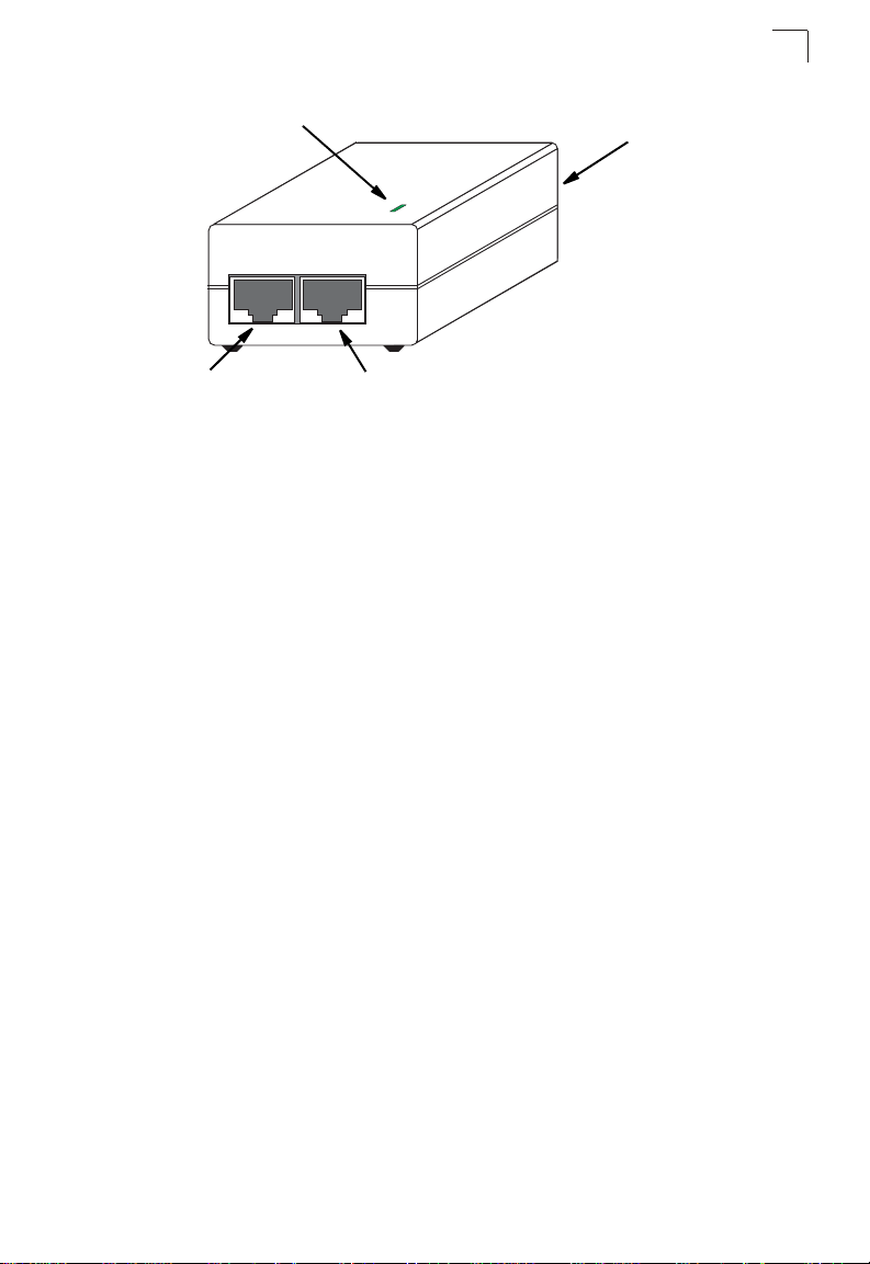
Power Injector Module
The wireless bridge receives power through its network cable connection using
power-over-Ethernet technology. A power injector module is included in the wireless
bridge package and provides two RJ-45 Ethernet ports, one for connecting to the
wireless bridge (Output), and the other for connecting to a local LAN switch (Input).
The Input port uses an MDI (i.e., internal straight-through) pin configuration. You can
therefore use straight-through twisted-pair cable to connect this port to most network
interconnection devices such as a switch or router that provide MDI-X ports.
However, when connecting the access point to a workstation or other device that
does not have MDI-X ports, you must use crossover twisted-pair cable.
1-4
Page 19
Hardware Description
1
Ethernet from
Local Network
LED Indicator
Input Output
Ethernet and Power to
Wireless Bridge
AC Power Socket
(Hidden)
The wireless bridge does not have a power switch. It is powered on when its
Ethernet port is connected to the power injector module, and the power injector
module is connected to an AC power source. The power injector includes one LED
indicator that turns on when AC power is applied.
The power injector module automatically adjusts to any AC voltage between
100-240 volts at 50 or 60 Hz. No voltage range settings are required.
Warning:The power injector module is designed for indoor use only. Never mount the
power injector outside with the wireless bridge unit.
Receive Signal Strength Indicator (RSSI) BNC Connector
The RSSI connector provides an output voltage that is proportional to the received
radio signal strength. A DC voltmeter can be connected the this port to assist in
aligning the antennas at both ends of a wireless bridge link.
Grounding Point
Even though the wireless bridge includes its own built-in lightning protection, it is
important that the unit is properly connected to ground. Two grounding screws are
provided for attaching a ground wire to the unit.
Wall- and Pole-Mounting Bracket Kits
The wireless bridge includes bracket kits that can be used to mount the bridge to a
wall, pole, radio mast, or part of a tower structure.
1-5
Page 20
Introduction
1
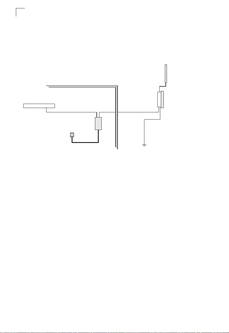
System Configuration
At each location where a unit is installed, it must be connected to the local network
using the power injector module. The following figure illustrates the system
component connections.
External Antenna
RF Coaxial Cable
Wireless Bridge Unit
LAN Switch
Indoor Outdoor
Ethernet Cable Ethernet Cable
Power
Injector
AC Power
Ground Wire
Features and Benefits
• Functioning as a slave the unit supports a 5 GHz point-to-point wireless link up 15.4
km (at 6 Mbps data rate) using integrated high-gain 16.5 dBi antennas
• Functioning as a master the unit support 5 GHz point-to-multipoint links using
various external antenna options
• The unit also supports access point services for the 5 GHz and 2.4 GHz radios
using various external antenna options
• Maximum data rate up to 108 Mbps on the 802.11a (5 GHz) radio
• Outdoor weatherproof design
• IEEE 802.11a and 802.11b/g compliant
• Local network connection via 10/100 Mbps Ethernet port
• Powered through its Ethernet cable connection to the power injector module
• Includes wall- and pole-mount brackets
• Security through 64/128/152-bit Wired Equivalent Protection (WEP) or 128-bit
Advanced Encryption Standard (AES) encryption
• Scans all available channels and selects the best channel and data rate based on
the signal-to-noise ratio
• Manageable through an easy-to-use web-browser interface, command line (via
Telnet), or SNMP network management tools
1-6
Page 21

System Defaults
1
System Defaults
The following table lists some of the wireless bridge’s basic system defaults. To
reset the bridge defaults, use the CLI command “reset configuration” from the Exec
level prompt.
Feature Parameter Default
Identification System Name Dual Band Outdoor AP
Administration User Name admin
Password null
General HTTP Server Enabled
HTTP Server Port 80
TCP/IP IP Address 192.168.1.1
Subnet Mask 255.255.255.0
Default Gateway 0.0.0.0
Primary DNS IP 0.0.0.0
Secondary DNS IP 0.0.0.0
VLANs Status Disabled
Native VLAN ID 1
Filter Control Ethernet Type Disabled
SNMP Status Enabled
Location null
Contact Contact
Community (Read Only) Public
Community (Read/Write) Private
Traps Enabled
Trap Destination IPAddress null
Trap Destination Community Name Public
System Logging Syslog Disabled
Logging Host Disabled
Logging Console Disabled
IP Address / Host Name 0.0.0.0
Logging Level Informational
Logging Facility Type 16
1-7
Page 22

Introduction
1
Feature Parameter Default
Spanning Tree Status Enabled
Ethernet Interface S pee d and Dup lex Auto
WDS Bridging Outdoor Bridge Band A (802.11a)
Wireless Interface
802.11a
Wireless Security
802.11a
Wireless Interface
802.11b/g
Status Enabled
SSID DualBandOutdoor
Turbo Mode Disabled
Radio Channel Default to first channel
Auto Channel Select Enabled
Transmit Power Full
Maximum Data Rate 54 Mbps
Beacon Interval 100 TUs
Data Beacon Rate (DTIM Interval) 2 beacons
RTS Threshold 2347 bytes
Authentication Type Open System
AES Encryption Disabled
WEP Encryption Disabled
WEP Key Length 128 bits
WEP Key Type Hexadecimal
WEP Transmit Key Number 1
Status Enabled
SSID DualBandOutdoor
Radio Channel Default to first channel
Auto Channel Select Enabled
Transmit Power Full
Maximum Data Rate 54 Mbps
Beacon Interval 100 TUs
Data Beacon Rate (DTIM Interval) 2 beacons
RTS Threshold 2347 bytes
1-8
Page 23

Feature Parameter Default
Wireless Security
802.11b/g
Authentication Type Open System
AES Encryption Disabled
WEP Encryption Disabled
WEP Key Length 128 bits
WEP Key Type Hexadecimal
WEP Transmit Key Number 1
WEP Keys null
WEP Keys null
System Defaults
1
1-9
Page 24

1
Introduction
1-10
Page 25

Chapter 2: Network Configuration
The Dual-band Outdoor Access Point / Bridge system provides access point or
bridging services through either the 5 GHz or 2.4 GHz radio interfaces.
The wireless bridge units can be used just as normal 802.11a/b/g access points
connected to a local wired LAN, providing connectivity and roaming services for
wireless clients in an outdoor area. Units can also be used purely as bridges
connecting remote LANs. Alternatively, you can employ both access point and
bridging functions together, offering a flexible and convenient wireless solution for
many applications.
This chapter describes the role of wireless bridge in various wireless network
configurations.
Access Point Topologies
Wireless networks support a stand-alone wireless configuration as well as an
integrated configuration with 10/100 Mbps Ethernet LANs.
Wireless network cards, adapters, and access points can be configured as:
• Ad hoc for departmental, SOHO, or enterprise LANs
• Infrastructure for wireless LANs
• Infrastructure wireless LAN for roaming wireless PCs
The 802.11b and 802.11g frequency band, which operates at 2.4 GHz, can easily
encounter interference from other 2.4 GHz devices, such as other 802.11b or g
wireless devices, cordless phones and microwave ovens. If you experience poor
wireless LAN performance, try the following measures:
• Limit any possible sources of radio interference within the service area
• Increase the distance between neighboring access points
• Increase the channel separation of neighboring access points (e.g., up to 3
channels of separation for 802.11b or up to 5 channels for 802.11g)
Ad Hoc Wireless LAN (no Access Point or Bridge)
An ad hoc wireless LAN consists of a group of computers, each equipped with a
wireless adapter, connected through radio signals as an independent wireless LAN.
Computers in a specific ad hoc wireless LAN must therefore be configured to the
same radio channel.
2-1
Page 26

Network Configuration
2
Ad Hoc Wireless LAN
Notebook with
Wireless USB Adapter
Notebook with
Wireless PC Card
PC with Wireless
PCI Adapter
Infrastructure Wireless LAN
The access point function of the wireless bridge provides access to a wired LAN for
802.11a/b/g wireless workstations. An integrated wired/wireless LAN is called an
Infrastructure configuration. A Basic Service Set (BSS) consists of a group of
wireless PC users and an access point that is directly connected to the wired LAN.
Each wireless PC in a BSS can connect to any computer in its wireless group or
access other computers or network resources in the wired LAN infrastructure
through the access point.
The infrastructure configuration not only extends the accessibility of wireless PCs to
the wired LAN, but also increases the effective wireless transmission range for
wireless PCs by passing their signals through one or more access points.
A wireless infrastructure can be used for access to a central database, or for
connection between mobile workers, as shown in the following figure.
2-2
Desktop PC
Wired LAN Extension
to Wireless Clients
Server
Switch
PC with Wireless
PCI Adapter
Notebook with Wireless
PC Card Adapter
Access Point
Page 27

Access Point Topologies
2
Infrastructure Wireless LAN for Roaming Wireless PCs
The Basic Service Set (BSS) defines the communications domain for each access
point and its associated wireless clients. The BSS ID is a 48-bit binary number
based on the access point’s wireless MAC address, and is set automatically and
transparently as clients associate with the access point. The BSS ID is used in
frames sent between the access point and its clients to identify traffic in the service
area.
The BSS ID is only set by the access point, never by its clients. The clients only
need to set the Service Set Identifier (SSID) that identifies the service set provided
by one or more access points. The SSID can be manually configured by the clients,
can be detected in an access point’s beacon, or can be obtained by querying for the
identity of the nearest access point. For clients that do not need to roam, set the
SSID for the wireless card to that used by the access point to which you want to
connect.
A wireless infrastructure can also support roaming for mobile workers. More than
one access point can be configured to create an Extended Service Set (ESS). By
placing the access points so that a continuous coverage area is created, wireless
users within this ESS can roam freely. All wireless network card adapters and
wireless access points within a specific ESS must be configured with the same
SSID.
Seamless Roaming
for Wireless Clients
Desktop PC
PC with Wireless
PCI Adapter
Switch
Access Point
Server
Switch
Notebook with Wireless
PC Card Adapter
<BSS1>
Access Point
<ESS>
Notebook with Wireless
PC Card Adapter
<BSS2>
2-3
Page 28

Network Configuration
2
Bridge Link Topologies
The IEEE 802.11 standard defines a WIreless Distribution System (WDS) for bridge
connections between BSS areas (access points). The outdoor wireless bridge uses
WDS to forward traffic on links between units. Up to 16 WDS links can be specified
for a OAP6626A unit configured as a “Master” in the wireless bridge network.
OAP6626A slave units support only one WDS link, which must be to the network’s
master unit.
The OAP6626A support WDS bridge links on either the 5 GHz (802.11a) or 2.4 GHz
(802.11b/g) bands and can be used with various external antennas to offer flexible
deployment options.
Note: The external antennas offer longer range options using the 5 GHz radio, which
makes this interface more suitable for bridge links. The 2.4 GHz radio has only the
8 dBi omnidirectional antenna option, which is better suited for local access point
services.
When using WDS on a radio band, only wireless bridge units can associate to each
other. Wireless clients can only associate with the wireless bridge using a radio band
set to access point mode.
Point-to-Point Configuration
Two OAP6626A bridges can form a wireless point-to-point link using their 5 GHz
(802.11a) integrated antennas. A point-to-point configuration can provide a limited
data rate (6 Mbps) link over a long range (up to 15.4 km), or a high data rate (108
Mbps) over a short range (1.3 km).
OAP6626A
LAN
up to 28 km at 36 Mbps
OAP6626A
LAN
Point-to-Multipoint Configuration
A OAP6626A configured as a “Master” wireless bridge can use an omnidirectional or
sector antenna to connect to as many as 16 bridges in a point-to-multipoint
configuration. There can only be one OAP6626A “Master” unit in the wireless bridge
network, all other bridges must be OAP6626A “Slave” units.
Using the 5 GHz 8 dBi omnidirectional external antenna, the Master unit can
connect to Slave units up to 3.3 km (2 miles) away. Using the 13.5 dBi 120-degree
sector antenna, the Master can connect to Slave units up to 10.3 km (6.4 miles)
away.
2-4
Page 29

Bridge Link Topologies
2
Slave
Slave
Slave
Master with
Sector Antenna
Master with
Omnidirectional
Antenna
Slave
Slave
Slave
Slave
Slave
2-5
Page 30

Network Configuration
2
2-6
Page 31

Chapter 3: Bridge Link Planning
The Dual-band Outdoor Access Point / Bridge supports fixed point-to-point or
point-to-multipoint wireless links. A single link between two points can be used to
connect a remote site to larger core network. Multiple bridge links can provide a way
to connect widespread Ethernet LANs.
For each link in a wireless bridge network to be reliable and provide optimum
performance, some careful site planning is required. This chapter provides guidance
and information for planning your wireless bridge links.
Note: The planning and installation of the wireless bridge requires professional
personnel that are trained in the installation of radio transmitting equipment. The
user is responsible for compliance with local regulations concerning items such as
antenna power, use of lightning arrestors, grounding, and radio mast or tower
construction. Therefore, it is recommended to consult a professional contractor
knowledgeable in local radio regulations prior to equipment installation.
Data Rates
Using its 5 GHz integrated antenna, the OAP6626A bridge can operate over a range
of up to 15.4 km (9.6 miles) or provide a high-speed connection of 54 Mbps (108
Mbps in turbo mode). However, the maximum data rate for a link decreases as the
operating range increases. A 15.4 km link can only operate up to 6 Mbps, whereas a
108 Mbps connection is limited to a range of 1.3 km.
When you are planning each wireless bridge link, take into account the maximum
distance and data rates for the various antenna options. A summary for 5 GHz
(802.11a) antennas is provided in the following table. For full specifications for each
antenna, see “Antenna Specifications” on page B-3.
.
Distances Achieved Using Normal Mode
Data Rate 17 dBi
Integrated
6 Mbps 15.4 km 3.3 km 10.3 km 14 km 24.4 km
9 Mbps 14.7 km 2.9 km 9.2 km 13.4 km 23.3 km
12 Mbps 14 km 2.6 km 8.2 km 12.8 km 22.2 km
18 Mbps 12.8 km 2.1 km 6.5 km 11.7 km 20.3 km
24 Mbps 11.1 km 1.5 km 4.6 km 9.2 km 17.7 km
36 Mbps 6.5 km 0.8 km 2.6 km 5.2 km 14 km
8 dBi Omni 13.5 dBi
120-Degree
Sector
16.5 dBi
60-Degree
Sector
23 dBi Panel
3-1
Page 32

Bridge Link Planning
3
Distances Achieved Using Normal Mode
Data Rate 17 dBi
Integrated
48 Mbps 2.9 km 0.4 km 1.2 km 2.3 km 9.2 km
54 Mbps 1.8 km 0.2 km 0.7 km 1.5 km 5.8 km
Distances provided in this table are an estimate for a typical deployment and may be reduced by local
regulatory limits. For accurate distances, you need to calculate the power link budget for your specific
environment.
.
Data Rate 17 dBi
Integrated
12 Mbps 13.4 km 2.3 km 7.3 km 12.2 km 21.2 km
18 Mbps 12.8 km 2.1 km 6.5 km 11.7 km 20.3 km
24 Mbps 12.2 km 1.8 km 5.8 km 11.1 km 19.4 km
36 Mbps 11.1 km 1.5 km 4.6 km 9.2 km 17.7 km
48 Mbps 8.2 km 1 km 3.3 km 6.5 km 15.4 km
72 Mbps 4.6 km 0.6 km 1.8 km 3.7 km 12.2 km
96 Mbps 2.1 km 0.3 km 0.8 km 1.6 km 6.5 km
108 Mbps 1.3 km 0.2 km 0.5 km 1 km 4.1 km
Distances provided in this table are an estimate for a typical deployment and may be reduced by local
regulatory limits. For accurate distances, you need to calculate the power link budget for your specific
environment.
8 dBi Omni 13.5 dBi
Distances Achieved Using Turbo Mode
8 dBi Omni 13.5 dBi
120-Degree
Sector
120-Degree
Sector
16.5 dBi
60-Degree
Sector
16.5 dBi
60-Degree
Sector
23 dBi Panel
23 dBi Panel
Radio Path Planning
Although the wireless bridge uses IEEE 802.11a radio technology, which is capable
of reducing the effect of multipath signals due to obstructions, the wireless bridge
link requires a “radio line-of-sight” between the two antennas for optimum
performance.
The concept of radio line-of-sight involves the area along a radio link path through
which the bulk of the radio signal power travels. This area is known as the first
Fresnel Zone of the radio link. For a radio link not to be affected by obstacles along
its path, no object, including the ground, must intrude within 60% of the first Fresnel
Zone.
3-2
Page 33

Radio Path Planning
The following figure illustrates the concept of a good radio line-of-sight.
3
Visual Line of Sight
If there are obstacles in the radio path, there may still be a radio link but the quality
and strength of the signal will be affected. Calculating the maximum clearance from
objects on a path is important as it directly affects the decision on antenna
placement and height. It is especially critical for long-distance links, where the radio
signal could easily be lost.
Note: For wireless links less than 500 m, the IEEE 802.11a radio signal will tolerate
some obstacles in the path and may not even require a visual line of sight between
the antennas.
When planning the radio path for a wireless bridge link, consider these factors:
• Avoid any partial line-of-sight between the antennas.
• Be cautious of trees or other foliage that may be near the path, or may grow and
obstruct the path.
• Be sure there is enough clearance from buildings and that no building construction
may eventually block the path.
• Check the topology of the land between the antennas using topographical maps,
aerial photos, or even satellite image data (software packages are available that
may include this information for your area)
• Avoid a path that may incur temporary blockage due to the movement of cars,
trains, or aircraft.
Radio Line of Sight
3-3
Page 34

Bridge Link Planning
3
Antenna Height
A reliable wireless link is usually best achieved by mounting the antennas at each
end high enough for a clear radio line of sight between them. The minimum height
required depends on the distance of the link, obstacles that may be in the path,
topology of the terrain, and the curvature of the earth (for links over 3 miles).
For long-distance links, a mast or pole may need to be contsructed to attain the
minimum required height. Use the following table to estimate the required minimum
clearance above the ground or path obstruction (for 5 GHz bridge links).
.
Total Link Distance Max Clearance for
60% of First Fresnel
Zone at 5.8 GHz
0.25 mile (402 m) 4.5 ft (1.4 m) 0 4.5 ft (1.4 m)
0.5 mile (805 m) 6.4 ft (1.95 m) 0 6.4 ft (1.95 m)
1 mile (1.6 km) 9 ft (2.7 m) 0 9 ft (2.7 m)
2 miles (3.2 km) 12.7 ft (3.9 m) 0 12.7 ft (3.9 m)
3 miles (4.8 km) 15.6 ft (4.8 m) 1.8 ft (0.5 m) 17.4 ft (5.3 m)
4 miles (6.4 km) 18 ft (5.5 m) 3.2 ft (1.0 m) 21.2 ft (6.5 m)
5 miles (8 km) 20 ft (6.1 m) 5 ft (1.5 m) 25 ft (7.6 m)
7 miles (11.3 km) 24 ft (7.3 m) 9.8 ft (3.0 m) 33.8 ft (10.3 m)
9 miles (14.5 km) 27 ft (8.2 m) 16 ft (4.9 m) 43 ft (13.1 m)
12 miles (19.3 km) 31 ft (9.5 m) 29 ft (8.8 m) 60 ft (18.3 m)
15 miles (24.1 km) 35 ft (10.7 m) 45 ft (13.7 m) 80 ft (24.4 m)
17 miles (27.4 km) 37 ft (11.3 m) 58 ft (17.7 m) 95 ft (29 m)
Approximate
Clearance for
Earth Curvature
Total Clearance
Required at
Mid-point of Link
Note that to avoid any obstruction along the path, the height of the object must be
added to the minimum clearance required for a clear radio line-of-sight. Consider the
following simple example, illustrated in the figure below.
3-4
Page 35

Radio Path Planning
3
Visual Line of Sight
3miles(4.8km)
2.4 m
A wireless bridge link is deployed to connect building A to a building B, which is
located three miles (4.8 km) away. Mid-way between the two buildings is a small
tree-covered hill. From the above table it can be seen that for a three-mile link, the
object clearance required at the mid-point is 5.3 m (17.4 ft). The tree-tops on the hill
are at an elevation of 17 m (56 ft), so the antennas at each end of the link need to be
at least 22.3 m (73 ft) high. Building A is six stories high, or 20 m (66 ft), so a 2.3 m
(7.5 ft) mast or pole must be contructed on its roof to achieve the required antenna
height. Building B is only three stories high, or 9 m (30 ft), but is located at an
elevation that is 12 m (39 ft) higher than bulding A. To mount an anntena at the
required height on building B, a mast or pole of only 1.3 m (4.3 ft) is needed.
Warning:Never construct a radio mast, pole, or tower near overhead power lines.
Note: Local regulations may limit or prevent construction of a high radio mast or tower. If
A
20 m
your wireless bridge link requires a high radio mast or tower, consult a
professional contractor for advice.
17 m
5.4 m
Radio Line of Sight
B
1.4 m
9m
12 m
Antenna Position and Orientation
Once the required antenna height has been determined, other factors affecting the
precise position of the wireless bridge must be considered:
• Be sure there are no other radio antennas within 2 m (6 ft) of the wireless bridge
• Place the wireless bridge away from power and telephone lines
• Avoid placing the wireless bridge too close to any metallic reflective surfaces, such
as roof-installed air-conditioning equipment, tinted windows, wire fences, or water
pipes
• The wireless bridge antennas at both ends of the link must be positioned with the
same polarization direction, either horizontal or vertical
Antenna Polarization — The wireless bridge’s integrated antenna sends a radio
signal that is polarized in a particular direction. The antenna’s receive sensitivity is
also higher for radio signals that have the same polarization. To maximize the
performance of the wireless link, both antennas must be set to the same polarization
3-5
Page 36

Bridge Link Planning
3
direction. The unit should be mounted with the antenna sockets facing upwards and
both console and POE ports pointing downwards.
Antenna sockets
should point upwards
in a vertical manner
Radio Interference
The avoidance of radio interference is an important part of wireless link planning.
Interference is caused by other radio transmissions using the same or an adjacent
channel frequency. You should first scan your proposed site using a spectrum
analyzer to determine if there are any strong radio signals using the 802.11a
channel frequencies. Always use a channel frequency that is furthest away from
another signal.
If radio interference is still a problem with your wireless bridge link, changing the
antenna polarization direction may improve the situation.
Weather Conditions
When planning wireless bridge links, you must take into account any extreme
weather conditions that are known to affect your location. Consider these factors:
• Temperature — The wireless bridge is tested for normal operation in temperatures
from -33°C to 55°C. Operating in temperatures outside of this range may cause the
unit to fail.
• Wind Velocity — The wireless bridge can operate in winds up to 90 MPH and
survive higher wind speeds up to 125 MPH. You must consider the known
maximum wind velocity and direction at the site and be sure that any supporting
structure, such as a pole, mast, or tower, is built to withstand this force.
• Lightning — The wireless bridge includes its own built-in lightning protection.
However, you should make sure that the unit, any supporting structure, and cables
3-6
Page 37

Ethernet Cabling
are all properly grounded. Additional protection using lightning rods, lightning
arrestors, or surge suppressors may also be employed.
• Rain — The wireless bridge is weatherproofed against rain. Also, prolonged heavy
rain has no significant effect on the radio signal. However, it is recommended to
apply weatherproof sealing tape around the Ethernet port and antenna connectors
for extra protection. If moisture enters a connector, it may cause a degradation in
performance or even a complete failure of the link.
• Snow and Ice — Falling snow, like rain, has no significant effect on the radio
signal. However, a build up of snow or ice on antennas may cause the link to fail.
In this case, the snow or ice has to be cleared from the antennas to restore
operation of the link.
3
Ethernet Cabling
When a suitable antenna location has been determined, you must plan a cable route
from the wireless bridge outdoors to the power injector module indoors. Consider
these points:
• The Ethernet cable length should never be longer than 100 m (328 ft)
• Determine a building entry point for the cable
• Determine if conduits, bracing, or other structures are required for safety or
protection of the cable
• For lightning protection at the power injector end of the cable, consider using a
lightning arrestor immediately before the cable enters the building
Grounding
It is important that the wireless bridge, cables, and any supporting structures are
properly grounded. The wireless bridge unit includes a grounding screw for
attaching a ground wire. Be sure that grounding is available and that it meets local
and national electrical codes.
3-7
Page 38

Bridge Link Planning
3
3-8
Page 39

Chapter 4: Hardware Installation
Before mounting antennas to set up your wireless bridge links, be sure you have
selected appropriate locations for each antenna. Follow the guidance and
information in Chapter 2, “Wireless Link Planning.”
Also, before mounting units in their intended locations, you should first perform initial
configuration and test the basic operation of the wireless bridge links in a controlled
environment over a very short range. (See the section “Testing Basic Link
Operation” in this chapter.)
The wireless bridge includes its own bracket kit for mounting the unit to a 1.5 to
2 inch diameter steel pole or tube. The pole-mounting bracket allows the unit to be
mounted to part of a radio mast or tower structure. The unit also has a wall-mounting
bracket kit that enables it to be fixed to a building wall or roof when using external
antennas.
Hardware installation of the wireless bridge involves these steps:
1. Mount the unit on a wall, pole, mast, or tower using the mounting bracket.
2. Mount external antennas on the same supporting structure as the bridge and
connect them to the bridge unit.
3. Connect the Ethernet cable and a grounding wire to the unit.
4. Connect the power injector to the Ethernet cable, a local LAN switch, and an
AC power source.
5. Align antennas at both ends of the link.
Testing Basic Link Operation
Set up the units over a very short range (15 to 25 feet), either outdoors or indoors.
Connect the units as indicated in this chapter and be sure to perform all the basic
configuration tasks outlined in Chapter 4, “Initial Configuration.” When you are
satisfied that the links are operating correctly, proceed to mount the units in their
intended locations.
Mount the Unit
Using the Pole-Mounting Bracket
Perform the following steps to mount the unit to a 1.5 to 2 inch diameter steel pole or
tube using the mounting bracket:
1. Always attach the bracket to a pole with the open end of the mounting grooves
facing up.
4-1
Page 40

Hardware Installation
4
2. Place the V-shaped part of the bracket around the pole and tighten the securing
nuts just enough to hold the bracket to the pole. (The bracket may need to be
rotated around the pole during the alignment process.)
Attach V-shaped
parts to pole with
provided nuts and
bolts
Slot the edges of
the V-shaped part
into the slats in the
rectangular plate,
and tighten the nuts
4-2
Page 41

Attach the
adjustable
rectangular plate to
the bridge with
supplied screws
Mount the Unit
4
Attach the bridge
with bracket to
afixed plate on pole
3. Use the included nuts to tightly secure the wireless bridge to the bracket. Be
sure to take account of the antenna polarization direction; all antennas in a link
must be mounted with the same polarization.
4-3
Page 42

Hardware Installation
4
Using the Wall-Mounting Bracket
Perform the following steps to mount the unit to a wall using the wall-mounting
bracket:
Note: The wall-mounting bracket does not allow the wireless bridge’s intrgrated antenna
to be aligned. It is intended for use with the unit using an external antenna.
1. Always attach the bracket to a wall with flat side flush against the wall (see
following figure).
2. Position the bracket in the intended location and mark the position of the three
mounting screw holes.
3. Drill three holes in the wall that match the screws and wall plugs included in the
bracket kit, then secure the bracket to the wall.
4. Use the included nuts to tightly secure the wireless bridge to the bracket.
4-4
Page 43

Connect External Antennas
Connect External Antennas
When deploying a OAP6626AM Master bridge unit for a bridge link or access point
operation, you need to mount external antennas and connect them to the bridge.
Typically, a bridge link requires a 5 GHz antenna, and access point operation a
2.4 GHz antenna. OAP6626A Slave units also require an external antenna for 2.4
GHz operation.
Perform these steps:
1. Mount the external antenna to the same supporting structure as the bridge,
within 3 m (10 ft) distance, using the bracket supplied in the antenna package.
4
2. Connect the antenna to the bridge’s N-type connector using the RF coaxial
cable provided in the antenna package.
3. Apply weatherproofing tape to the antenna connectors to help prevent water
entering the connectors.
4-5
Page 44

Hardware Installation
4
OAP6626A
2.4 GHz
N-type Connector
5 GHz
N-type Connector
2.4 GHz
N-type Connector
RF Coaxial Cable
5 GHz External
High-gain Panel
Antenna
2.4 GHz External
Omnidirectional
Antenna
Connect Cables to the Unit
1. Attach the Ethernet cable to the Ethernet port on the wireless bridge.
Note: The Ethernet cable included with the package is 30 m (100 ft) long. To wire a
longer cable (maximum 100 m, 325 ft), use the connector pinout information in
Appendix B.
2. For extra protection against rain or moisture, apply weatherproofing tape (not
included) around the Ethernet connector.
3. Be sure to ground the unit with an appropriate grounding wire (not included) by
attaching it to the grounding screw on the unit.
Caution: Be sure that grounding is available and that it meets local and national
electrical codes. For additional lightning protection, use lightning rods, lightning
arrestors, or surge suppressors.
4-6
Page 45

Connect the Power Injector
Ground Wire
Ethernet Cable
4
Connect the Power Injector
To connect the wireless bridge to a power source:
Caution: Do not install the power injector outdoors. The unit is for indoor installation only.
Note: The wireless bridge’s Ethernet port does not support Power over Ethernet (PoE)
based on the IEEE 802.3af standard. Do not try to power the unit by connecting it
directly to a network switch that provides IEEE 802.3af PoE. Always connect the
unit to the included power injector module.
1. Connect the Ethernet cable from the wireless bridge to the RJ-45 port labeled
“Output” on the power injector.
2. Connect a straight-through unshielded twisted-pair (UTP) cable from a local
LAN switch to the RJ-45 port labeled “Input” on the power injector. Use
Category 5 or better UTP cable for 10/100BASE-TX connections.
Note: The RJ-45 port on the power injector is an MDI port. If connecting directly to a
computer for testing the link, use a crossover cable.
4-7
Page 46

Hardware Installation
4
AC power
Ethernet cable
from LAN switch
Input
Output
Power LED indicator
Ethernet cable to
wireless bridge
3. Insert the power cable plug directly into the standard AC receptacle on the
power injector.
4. Plug the other end of the power cable into a grounded, 3-pin socket, AC power
source.
Note: For International use, you may need to change the AC line cord. You must use a
line cord set that has been approved for the receptacle type in your country.
5. Check the LED on top of the power injector to be sure that power is being
supplied to the wireless bridge through the Ethernet connection.
Align Antennas
After wireless bridge units have been mounted, connected, and their radios are
operating, the antennas must be accurately aligned to ensure optimum performance
on the bridge links. This alignment process is particularly important for long-range
point-to-point links. In a point-to-multipoint configuration the Master bridge uses an
omnidirectional or sector antenna, which does not require alignment, but Slave
bridges still need to be correctly aligned with the Master bridge antennna.
• Point-to-Point Configurations – In a point-to-point configuration, the alignment
process requires two people at each end of the link. The use of cell phones or
two-way radio communication may help with coordination. To start, you can just
point the antennas at each other, using binoculars or a compass to set the general
direction. For accurate alignment, you must connect a DC voltmeter to the RSSI
connector on the wireless bridge and monitor the voltage as the antenna moves
horizontally and vertically.
• Point-to-Multipoint Configurations – In a point-to-multipoint configuration all
Slave bridges must be aligned with the Master bridge antenna. The alignment
process is the same as in point-to-point links, but only the Slave end of the link
requires the alignment.
4-8
Page 47

Align Antennas
4
The RSSI connector provides an output voltage between 0 and 3.28 VDC that is
proportional to the received radio signal strength. The higher the voltage reading,
the stronger the signal. The radio signal from the remote antenna can be seen to
have a strong central main lobe and smaller side lobes. The object of the alignment
process is to set the antenna so that it is receiving the strongest signal from the
central main lobe.
Vertical Scan
Remote
Antenna
Horizontal Scan
RSSI
Voltage
Main Lobe
Maximum
Maximum Signal Strength Position
for Horizontal Alignment
RSSI Voltage
Side Lobe
Maximum
Maximum Signal
Strength Position for
Vertical Alignment
To align the antennas in the link using the RSSI output voltage, start with one
antenna fixed and then perform the following procedure on the other antenna:
Note: The RSSI output can be configured through management interfaces to output a
value for specific WDS ports.
1. Remove the RSSI connector cover and connect a voltmeter using a cable with
a male BNC connector (not included).
4-9
Page 48

Hardware Installation
4
Voltmeter
2. Pan the antenna horizontally back and forth while checking the RSSI voltage. If
using the pole-mounting bracket with the unit, you must rotate the mounting
bracket around the pole. Other external antenna brackets may require a
different horizontal adjustment.
3. Find the point where the signal is strongest (highest voltage) and secure the
horizontal adjustment in that position.
Note: Sometimes there may not be a central lobe peak in the voltage because vertical
alignment is too far off; only two similar peaks for the side lobes are detected. In
this case, fix the antenna so that it is halfway between the two peaks.
4. Loosen the vertical adjustment on the mounting bracket and tilt the antenna
slowly up and down while checking the RSSI voltage.
5. Find the point where the signal is strongest and secure the vertical adjustment
in that position.
6. Remove the voltmeter cable and replace the RSSI connector cover.
RSSI
Connection
4-10
Page 49

Appendix A: Troubleshooting
Check the following items before you contact local Technical Support.
1. If wireless bridge units do not associate with each other, check the following:
• Check the power injector LED for each bridge unit to be sure that power is
being supplied
• Be sure that antennas in the link are properly aligned.
• Be sure that channel settings match on all bridges
• If encryption is enabled, ensure that all bridge links are configured with the
same encryption keys.
2. If you experience poor performance (high packet loss rate) over the wireless
bridge link:
• Check that the range of the link is within the limits for the antennas used.
• Be sure that antennas in the link are properly aligned.
• Check that there is an unobstructed radio line-of-sight between the antennas.
• Be sure there is no interference from other radio sources. Try setting the
bridge link to another radio channel.
• Be sure there is no other radio transmitter too close to either antenna. If
necessary, move the antennas to another location.
3. If the wireless bridge cannot be configured using Telnet, a web browser, or
SNMP software:
• Be sure to have configured the wireless bridge with a valid IP address, subnet
mask and default gateway.
• Check that you have a valid network connection to the wireless bridge and
that the Ethernet port or the wireless interface has not been disabled.
• If you are connecting to the wireless bridge through the wired Ethernet
interface, check the network cabling between the management station and the
wireless bridge.
• If you cannot connect using Telnet, you may have exceeded the maximum
number of concurrent Telnet sessions permitted (i.e, four sessions). Try
connecting again at a later time.
4. If all other recovery measures fail, and the wireless bridge is still not functioning
properly, take any of these steps:
• Reset the wireless bridge’s hardware using the CLI, web interface, or through
a power reset.
• Reset the wireless bridge to its default configuration.
A-1
Page 50

Troubleshooting
A
5. If you forgot or lost the password:
• Contact Technical Support.
A-2
Page 51

Appendix B: Specifications
General Specifications
Maximum Channels (Outdoor)
802.11a:
US & Canada: 9 (normal mode), 3 (turbo mode)
Japan: 4 (normal mode), 1 (turbo mode)
ETSI: 11 channels (normal mode), 4 (turbo mode)
Taiwan: 4 (normal mode), 1 (turbo mode)
802.11g:
FCC/IC: 1-11
ETSI: 1-13
France: 1-7
MKK: 1-14
Tai w an : 1- 11
Data Rates
802.11a:
Normal Mode: 6, 9, 12, 18, 24, 36, 48, 54 Mbps per channel
Turbo Mode: 12, 18, 24, 36, 48, 72, 96, 108 Mbps per channel
802.11g:
6, 9, 11, 12, 18, 24, 36, 48, 54 Mbps per channel
802.11b:
1, 2, 5.5, 11 Mbps per channel
Maximum Clients
64 for the radio interface set to access point mode
Modulation Types
802.11a: BPSK, QPSK, 16-QAM, 64-QAM
802.11g: CCK, BPSK, QPSK, OFDM
802.11b: CCK, BPSK, QPSK
Network Configuration
Bridge Mode:
Point-to-point and point-to-multipoint
Access Point Mode:
Infrastructure
B-1
Page 52

Specifications
B
Operating Frequency
802.11a:
5.15 ~ 5.25 GHz (lower band) US/Canada
5.25 ~ 5.35 GHz (middle band) US/Canada
5.725 ~ 5.825 GHz (upper band) US/Canada
5.25 ~ 5.35 GHz (middle band) Taiwan
5.725 ~ 5.825 GHz (high band) Taiwan
802.11b/g:
2.4 ~ 2.4835 GHz (US, Canada, ETSI)
2.4 ~ 2.497 GHz (Japan)
2.400 ~ 2.4835 GHz (Taiwan)
Power Injector
Input: 100-240 VAC, 47-63 Hz, 1.5 A
Output: 48 VDC, 1.2 A
Bridge Power (DC)
Input voltage: 48 volts, 1.2 A, 30 watts maximum
Physical Size
19.8 x 19.8 x 6.33 cm (7.8 x 7.8 x 2.49 in)
Weight
4.8 kg (10.58 lbs)
Network Management
Web-browser, Telnet, SNMP
Tem perat ure
Operating: -33 to 55 °C (-27.4 to 131 °F)
Storage: -40 to 80 °C (-40 to 176 °F)
Humidity
5% to 95% (non-condensing)
EMC Compliance (Class B)
FCC Class B (US)
RTTED 1999/5/EC
DGT (Taiwan)
B-2
Page 53

Radio Signal Certification
FCC Part 15 15.407(b) (5 GHz)
FCC Part 15.247 (2.4 GHz)
EN 300.328, EN 302.893
EN 300 826, EN 301.489-1, EN 301.489-17
ETSI 300.328; ETS 300 826 (802.11b)
Safety
CSA/NTRL (CSA 22.2 No. 950 & UL 1950)
Standards
IEEE 802.3 10BASE-T, IEEE 802.3u 100BASE-TX,
IEEE 802.11a, b, g
Antenna Specifications
17 dBi Integrated Panel
Frequency Range
5.150 - 5.850 GHz
Gain
17 dBi
VSWR
1.8 : 1 max
Antenna Specifications
B
Polarization
Linear, vertical/horizontal
HPBW
Horizontal: 20°
Vertical: 22°
Front-to-Back Ratio
>25 dB
Power Handling
10 W (cw)
Impedance
50 Ohms
Connector
SMA female
B-3
Page 54

Specifications
B
17 dBi Integrated Panel Antenna Link Budget
(5.825 GHz, Cable Loss 1 dB, Fade Margin 5 dB)
Modulation/Rates Transmit Power
Normal Mode
BPSK (6 Mbps) 20 -88 15.4
BPSK (9 Mbps) 20 -87 14.7
QPSK (12 Mbps) 20 -86 14.0
QPSK (18 Mbps) 20 -84 12.8
16 QAM (24 Mbps) 20 -81 11.1
16 QAM (36 Mbps) 20 -76 6.5
64 QAM (48 Mbps) 18 -71 2.9
64 QAM (54 Mbps) 17 -68 1.8
Turbo Mode
BPSK (12 Mbps) 20 -85 13.4
BPSK (18 Mbps) 20 -84 12.8
QPSK (24 Mbps) 20 -83 12.2
QPSK (36 Mbps) 20 -81 11.1
16 QAM (48 Mbps) 20 -78 8.2
16 QAM (72 Mbps) 20 -73 4.6
64 QAM (96 Mbps) 18 -68 2.1
64 QAM (108 Mbps) 17 -65 1.3
* The maximum range calculated with a 17 dBi panel antenna at the far end of the link.
The maximum transmit power (hence range) may be lowered by regulatory (FCC etc) EIRP (effective
isotropic radiated power) limits.
(dBm)
Receive Sensitivity
(dBm)
Maximum Range (km)
with 17 dBi Panel*
8 dBi Omnidirectional (2.4 GHz)
Model Number
R0205-135
Frequency Range
2.400 - 2.500 GHz
Gain
8 dBi
VSWR
2.0 : 1 max
Polarization
Linear, vertical
B-4
Page 55

HPBW
Horizontal: 360°
Vertical: 15°
Downtilt
0°
Power Handling
50 W (cw)
Impedance
50 Ohms
Connector
N type, male
Radome
Material: Fiber glass
Color: Gray-white
Environmental
Survival Wind Speed: 216 km/hr
Temperature: -40 °C to 80 °C
Humidity: 95% @ 25 °C
Mechanical
Dimensions: 46 x 1.9 cm (diameter) (18.11 x 0.75 in)
Weight: 200 g (0.44 lbs)
Antenna Specifications
B
8 dBi Omnidirectional Antenna Link Budget
(2.483 GHz, Cable Loss 0 dB, Fade Margin 3 dB)
Modulation/Rates Transmit Power
BPSK (6 Mbps) 20 -88 7.641
BPSK (9 Mbps) 20 -87 6.810
QPSK (12 Mbps) 20 -86 6.070
QPSK (18 Mbps) 20 -84 4.821
16 QAM (24 Mbps) 20 -81 3.413
16 QAM (36 Mbps) 20 -76 2.154
64 QAM (48 Mbps) 19 -71 1.079
64 QAM (54 Mbps) 18 -68 0.541
* The maximum range calculated with a 2 dBi NIC antenna at the far end of the link.
The maximum transmit power (hence range) may be lowered by regulatory (FCC etc) EIRP (effective
isotropic radiated power) limits.
(dBm)
Receive Sensitivity
(dBm)
Maximum Range (km)
with 2 dBi NIC
B-5
Page 56

Specifications
B
8 dBi Omnidirectional (5 GHz)
Model Number
MTI 09038
Frequency range
5.725 - 5.875 GHz
Gain
8 dBi
VSWR
2.0 : 1 max
Polarization
Linear, vertical
HPBW
Horizontal: 360°
Vertical: 12°
Downtilt
0°
Power Handling
5 W (cw)
Impedance
50 Ohms
Connector
N type, female
Radome
Material: Fiber glass
Color: Gray-white
Environmental
Survival Wind Speed: 216 km/hr
Temperature: -40 °C to 80 °C
Humidity: 95% @ 25 °C
Mechanical
Dimensions: 7 x 8 x 37.3 cm (2.76 x 3.15 x 14.69 in)
Weight: 245 g (0.54 lbs)
B-6
Page 57

Antenna Specifications
8 dBi Omnidirectional Antenna Link Budget
(5.825 GHz, Cable Loss 0 dB, Fade Margin 3 dB)
Modulation/Rates Transmit Power
Normal Mode
BPSK (6 Mbps) 20 -88 3.3
BPSK (9 Mbps) 20 -87 2.9
QPSK (12 Mbps) 20 -86 2.6
QPSK (18 Mbps) 20 -84 2.1
16 QAM (24 Mbps) 20 -81 1.5
16 QAM (36 Mbps) 20 -76 0.8
64 QAM (48 Mbps) 18 -71 0.4
64 QAM (54 Mbps) 17 -68 0.2
Turbo Mode
BPSK (12 Mbps) 20 -85 2.3
BPSK (18 Mbps) 20 -84 2.1
QPSK (24 Mbps) 20 -83 1.8
QPSK (36 Mbps) 20 -81 1.5
16 QAM (48 Mbps) 20 -78 1.0
16 QAM (72 Mbps) 20 -73 0.6
64 QAM (96 Mbps) 18 -68 0.3
64 QAM (108 Mbps) 17 -65 0.2
* The maximum range calculated with a 2 dBi NIC antenna at the far end of the link.
The maximum transmit power (hence range) may be lowered by regulatory (FCC etc) EIRP (effective
isotropic radiated power) limits.
(dBm)
Receive Sensitivity
(dBm)
Maximum Range (km)
with 2 dBi NIC
B
13.5 dBi 120-Degree Sector
Model Number
R0320-099
Frequency range
5.150 - 5.875 GHz
Gain
13.5 dBi
VSWR
2.0 : 1 max
Polarization
Linear, vertical
B-7
Page 58

Specifications
B
HPBW
Horizontal: 120°
Vertical: 6°
Downtilt
0°
Power Handling
5 W (cw)
Impedance
50 Ohms
Connector
N type, female
Radome
Material: ABS
Color: Gray, white
Environmental
Survival Wind Speed: 216 km/hr
Temperature: -40 °C to 80 °C
Humidity: 95% @ 25 °C
Mechanical
Dimensions: 62 x 8.8 x 7 cm (24.4 x 3.46 x 2.76 in)
Weight: 590 g (1.3 lbs)
13.5 dBi 120-Degree Sector Antenna Link Budget
(5.825 GHz, Cable Loss 1 dB, Fade Margin 5 dB)
Modulation/Rates Transmit Power
Normal Mode
BPSK (6 Mbps) 20 -88 10.3
BPSK (9 Mbps) 20 -87 9.2
QPSK (12 Mbps) 20 -86 8.2
QPSK (18 Mbps) 20 -84 6.5
16 QAM (24 Mbps) 20 -81 4.6
16 QAM (36 Mbps) 20 -76 2.6
64 QAM (48 Mbps) 18 -71 1.2
64 QAM (54 Mbps) 17 -68 0.7
Turbo Mode
BPSK (12 Mbps) 20 -85 7.3
BPSK (18 Mbps) 20 -84 6.5
(dBm)
Receive Sensitivity
(dBm)
Maximum Range (km)
with 13.5 dBi Sector
B-8
Page 59

Antenna Specifications
13.5 dBi 120-Degree Sector Antenna Link Budget
(5.825 GHz, Cable Loss 1 dB, Fade Margin 5 dB)
Modulation/Rates Transmit Power
QPSK (24 Mbps) 20 -83 5.8
QPSK (36 Mbps) 20 -81 4.6
16 QAM (48 Mbps) 20 -78 3.3
16 QAM (72 Mbps) 20 -73 1.8
64 QAM (96 Mbps) 18 -68 0.8
64 QAM (108 Mbps) 17 -65 0.5
* The maximum range calculated with a 13.5 dBi sector antenna at the far end of the link.
The maximum transmit power (hence range) may be lowered by regulatory (FCC etc) EIRP (effective
isotropic radiated power) limits.
(dBm)
Receive Sensitivity
(dBm)
Maximum Range (km)
with 13.5 dBi Sector
16.5 dBi 60-Degree Sector
Model Number
R0320-100
Frequency range
5.150 - 5.875 GHz
Gain
16.5 dBi
B
VSWR
2.0 : 1 max
Polarization
Linear, vertical
HPBW
Horizontal: 60°
Vertical: 6°
Downtilt
0°
Power Handling
5 W (cw)
Impedance
50 Ohms
Connector
N type, female
B-9
Page 60

Specifications
B
Radome
Material: ABS
Color: Gray, white
Environmental
Survival Wind Speed: 216 km/hr
Temperature: -40 °C to 80 °C
Humidity: 95% @ 25 °C
Mechanical
Dimensions: 62 x 8.8 x 7 cm (24.41 x 3.46 x 2.76 in)
Weight: 565 g (1.25 lbs)
16.5 dBi 60-Degree Sector Antenna Link Budget
(5.825 GHz, Cable Loss 1 dB, Fade Margin 5 dB)
Modulation/Rates Transmit Power
(dBm)
Normal Mode
BPSK (6 Mbps) 20 -88 14.0
BPSK (9 Mbps) 20 -87 13.4
QPSK (12 Mbps) 20 -86 12.8
QPSK (18 Mbps) 20 -84 11.7
16 QAM (24 Mbps) 20 -81 9.2
16 QAM (36 Mbps) 20 -76 5.2
64 QAM (48 Mbps) 18 -71 2.3
64 QAM (54 Mbps) 17 -68 1.5
Turbo Mode
BPSK (12 Mbps) 20 -85 12.2
BPSK (18 Mbps) 20 -84 11.7
QPSK (24 Mbps) 20 -83 11.1
QPSK (36 Mbps) 20 -81 9.2
16 QAM (48 Mbps) 20 -81 6.5
16 QAM (72 Mbps) 20 -78 3.7
64 QAM (96 Mbps) 18 -73 1.6
64 QAM (108 Mbps) 17 -68 1.0
* The maximum range calculated with a 16.5 dBi sector antenna at the far end of the link.
The maximum transmit power (hence range) may be lowered by regulatory (FCC etc) EIRP (effective
isotropic radiated power) limits.
Receive Sensitivity
(dBm)
Maximum Range (km)
with 16.5 dBi Sector
B-10
Page 61

23 dBi High-Gain Panel
Model Number
MTI 09009
Frequency range
5.725 - 5.875 GHz
Gain
23 dBi
VSWR
1.5 : 1 max
Polarization
Linear, vertical/horizontal
HPBW
Horizontal: 9°
Vertical: 9°
Front-to-Back Ratio
40 dB
Cross Polarization
25 dB
Power Handling
20 W (cw)
Antenna Specifications
B
Impedance
50 Ohms
Connector
N type, female
Radome
Material: ABS, UV resistant
Color: White
Environmental
Survival Wind Speed: 216 km/hr
Temperature: -40 °C to 80 °C
Humidity: 95% @ 25 °C
Mechanical
Dimensions: 36 x 36 x 1.6 cm (14.17 x 14.17 x 0.63 in)
Weight: 1600 g (3.53 lbs)
B-11
Page 62

Specifications
B
23 dBi Panel Antenna Link Budget
(5.825 GHz, Cable Loss 1 dB, Fade Margin 5 dB)
Modulation/Rates Transmit Power
Normal Mode
BPSK (6 Mbps) 20 -88 24.4
BPSK (9 Mbps) 20 -87 23.3
QPSK (12 Mbps) 20 -86 22.2
QPSK (18 Mbps) 20 -84 20.3
16 QAM (24 Mbps) 20 -81 17.7
16 QAM (36 Mbps) 20 -76 14.0
64 QAM (48 Mbps) 18 -71 9.2
64 QAM (54 Mbps) 17 -68 5.8
Turbo Mode
BPSK (12 Mbps) 20 -85 21.2
BPSK (18 Mbps) 20 -84 20.3
QPSK (24 Mbps) 20 -83 19.4
QPSK (36 Mbps) 20 -81 17.7
16 QAM (48 Mbps) 20 -78 15.4
16 QAM (72 Mbps) 20 -73 12.2
64 QAM (96 Mbps) 18 -68 6.5
64 QAM (108 Mbps) 17 -65 4.1
* The maximum range calculated with a 23 dBi panel antenna at the far end of the link.
The maximum transmit power (hence range) may be lowered by regulatory (FCC etc) EIRP (effective
isotropic radiated power) limits.
(dBm)
Receive Sensitivity
(dBm)
Maximum Range (km)
with 23 dBi Panel
B-12
Page 63

Appendix C: Cables and Pinouts
Twisted-Pair Cable Assignments
For 10/100BASE-TX connections, a twisted-pair cable must have two pairs of wires.
Each wire pair is identified by two different colors. For example, one wire might be
green and the other, green with white stripes. Also, an RJ-45 connector must be
attached to both ends of the cable.
Caution: Each wire pair must be attached to the RJ-45 connectors in a specific
Caution: DO NOT plug a phone jack connector into a power injector RJ-45 port. Use
The following figure illustrates how the pins on the RJ-45 connector are numbered.
Be sure to hold the connectors in the same orientation when attaching the wires to
the pins.
orientation.
only twisted-pair cables with RJ-45 connectors that conform with FCC
standards.
8
1
8
C-1
Page 64

Cables and Pinouts
C
10/100BASE-TX Pin Assignments
Use unshielded twisted-pair (UTP) or shielded twisted-pair (STP) cable for RJ-45
connections: 100-ohm Category 3 or better cable for 10 Mbps connections, or
100-ohm Category 5 or better cable for 100 Mbps connections. Also be sure
that the
length of any twisted-pair connection does not exceed 100 meters (328 feet).
The RJ-45 Input port on the power injector is wired with MDI pinouts. This means
that you must use crossover cables for connections to PCs or servers, and
straight-through cable for connections to switches or hubs. However, when
connecting to devices that support automatic MDI/MDI-X pinout configuration, you
can use either straight-through or crossover cable.
10/100BASE-TX MDI and MDI-X Port Pinouts
Pin MDI-X Signal Name MDI Signal Name
1 Receive Data plus (RD+) Transmit Data plus (TD+)
2 Receive Data minus (RD-) Transmit Data minus (TD-)
3 Transmit Data plus (TD+) Receive Data plus (RD+)
6 Transmit Data minus (TD-) Receive Data minus (RD-)
4,5,7,8 Not used Not used
Note: The “+” and “-” signs represent the polarity of the wires that make up each wire pair.
Straight-Through Wiring
Because the 10/100 Mbps Input port on the power injector uses an MDI pin
configuration, you must use “straight-through” cable for network connections to hubs
or switches that only have MDI-X ports. However, if the device to which you are
connecting supports automatic MDI/MDI-X operation, you can use either
“straight-through” or “crossover” cable.
EIA/TIA 568B RJ-45 WiringStandard
10/100BASE-TX Straight-through Cable
White/Orange Stripe
Orange
End A
1
2
3
4
5
6
7
8
White/Green Stripe
Blue
White/Blue Stripe
Green
White/Brown Stripe
Brown
1
2
3
4
5
6
7
8
End B
C-2
Page 65

8-Pin DIN Connector Pinout
C
Crossover Wiring
Because the 10/100 Mbps port on the power injector uses an MDI pin configuration,
you must use “crossover” cable for network connections to PCs, servers or other
end nodes that only have MDI ports. However, if the device to which you are
connecting supports automatic MDI/MDI-X operation, you can use either
“straight-through” or “crossover” cable.
EIA/TIA 568B RJ-45 WiringStandard
10/100BASE-TX Crossover Cable
White/Orange Stripe
Orange
End A
1
2
3
4
5
6
7
8
White/Green Stripe
Blue
White/Blue Stripe
Green
White/Brown Stripe
Brown
1
2
3
4
5
6
7
8
End B
8-Pin DIN Connector Pinout
The Ethernet cable from the power injector connects to an 8-pin DIN connector on
the wireless bridge. This connector is described in the following figure and table.
2
3
4
5
8-Pin DIN Ethernet Por t Pinout
Pin Signal Name
1 Transmit Data plus (TD+)
2 Transmit Data minus (TD-)
3 Receive Data plus (RD+)
4 +48 VDC power
5 +48 VDC power
6 Receive Data minus (RD-)
7 Return power
8 Return power
Note: The “+” and “-” signs represent the polarity of the
wires that make up each wire pair.
1
7
8
6
C-3
Page 66

Cables and Pinouts
C
8-Pin DIN to RJ-45 Cable Wiring
To construct an extended Ethernet cable to connect from the power injector’s RJ-45
Output port to the wireless bridge’s 8-pin DIN connector, follow the wiring diagram
below. Use Category 5 or better UTP or STP cable, maximum length 100 m (328 ft),
and be sure to connect all four wire pairs.
Note: To construct a reliable Ethernet cable, always use the proper tools or ask a
professional cable supplier to construct the cable.
White/Orange Stripe
Orange
8-Pin DIN
Female
1
7
6
5
8-Pin DIN Female
Front View
1
2
3
4
5
6
7
8
2
3
8
4
White/Green Stripe
Blue
White/Blue Stripe
Green
White/Brown Stripe
Brown
1
2
3
4
5
6
7
8
RJ-45
C-4
Page 67

Glossary
10BASE-T
IEEE 802.3 specification for 10 Mbps Ethernet over two pairs of Category 3 or better
UTP cable.
100BASE-TX
IEEE 802.3u specification for 100 Mbps Fast Ethernet over two pairs of Category 5
or better UTP cable.
Access Point
An internetworking device that seamlessly connects wired and wireless networks.
Access points attached to a wired network, support the creation of multiple radio
cells that enable roaming throughout a facility.
Advanced Encryption Standard (AES)
An encryption algorithm that implements symmetric key cryptography. AES provides
very strong encryption using a completely different ciphering algorithm to TKIP and
WEP.
Authentication
The process to verify the identity of a client requesting network access. IEEE 802.11
specifies two forms of authentication: open system and shared key.
Backbone
The core infrastructure of a network. The portion of the network that transports
information from one central location to another central location where it is unloaded
onto a local system.
Basic Service Set (BSS)
A set of 802.11-compliant stations and an access point that operate as a
fully-connected wireless network.
Beacon
A signal periodically transmitted from the access point that is used to identify the
service set, and to maintain contact with wireless clients.
CSMA/CA
Carrier Sense Multiple Access with Collision Avoidance.
Glossary-1
Page 68

Glossary
dBm
The unit dBm refers to a precise measure of power based upon the decibel scale,
but referenced to the milliwatt: i.e. 1 dBm = .001 Watt. The dBm is often used to
describe absolute power level where the point of reference is 1 milliwatt.
Dynamic Host Configuration Protocol (DHCP)
Provides a framework for passing configuration information to hosts on a TCP/IP
network. DHCP is based on the Bootstrap Protocol (BOOTP), adding the capability
of automatic allocation of reusable network addresses and additional configuration
options.
Encryption
Data passing between the access point and clients can use encryption to protect
from interception and evesdropping.
Ethernet
A popular local area data communications network, which accepts transmission
from computers and terminals.
File Transfer Protocol (FTP)
A TCP/IP protocol used for file transfer.
Hypertext Transfer Protocol (HTTP)
HTTP is a standard used to transmit and receive all data over the World Wide Web.
IEEE 802.11a
A wireless standard that supports high-speed communications in the 5 GHz band
using Orthogonal Frequency Division Multiplexing (OFDM). The standard supports
data rates of 6, 12, 24, and 54 Mbps.
Local Area Network (LAN)
A group of interconnected computer and support devices.
MAC Address
The physical layer address used to uniquely identify network nodes.
Network Time Protocol (NTP)
NTP provides the mechanisms to synchronize time across the network. The time
servers operate in a hierarchical-master-slave configuration in order to synchronize
local clocks within the subnet and to national time standards via wire or radio.
Open System
A security option which broadcasts a beacon signal including the access point’s
configured SSID. Wireless clients can read the SSID from the beacon, and
Glossary-2
Page 69

Glossary
automatically reset their SSID to allow immediate connection to the nearest access
point.
Orthogonal Frequency Division Multiplexing (ODFM)
OFDM/ allows multiple users to transmit in an allocated band by dividing the
bandwidth into many narrow bandwidth carriers.
RTS Threshold
Transmitters contending for the medium may not be aware of each other. RTS/CTS
mechanism can solve this “Hidden Node Problem.” If the packet size is smaller than
the preset RTS Threshold size, the RTS/CTS mechanism will NOT be enabled.
Service Set Identifier (SSID)
An identifier that is attached to packets sent over the wireless LAN and functions as
a password for joining a particular radio cell; i.e., Basic Service Set (BSS).
Session Key
Session keys are unique to each client, and are used to authenticate a client
connection, and correlate traffic passing between a specific client and the access
point.
Shared Key
A shared key can be used to authenticate each client attached to a wireless network.
Shared Key authentication must be used along with the 802.11 Wireless Equivalent
Privacy algorithm.
Simple Network Management Protocol (SNMP)
The application protocol in the Internet suite of protocols which offers network
management services.
Simple Network Time Protocol (SNTP)
SNTP allows a device to set its internal clock based on periodic updates from a
Network Time Protocol (NTP) server. Updates can be requested from a specific NTP
server, or can be received via broadcasts sent by NTP servers.
Trivial File Transfer Protocol (TFTP)
A TCP/IP protocol commonly used for software downloads.
Wired Equivalent Privacy (WEP)
WEP is based on the use of security keys and the popular RC4 encryption
algorithm. Wireless devices without a valid WEP key will be excluded from network
traffic.
Glossary-3
Page 70

Glossary
Glossary-4
Page 71

Index
B
Basic Service Set See BSS
BSS 2-2
C
cable
assignments C-1
crossover C-3
straight-through C-2
channels, maximum B-1
clients, maximum B-1
crossover cable C-3
CSMA/CA 1-1
D
data rate, options B-1
default settings 1-7
E
Ethernet
port 1-4
I
IEEE 802.11a 1-1
installation
hardware 4-1
PoE 4-7
specifications B-2
Power over Ethernet See PoE
power supply, specifications B-2
R
reset button 1-4
RSSI BNC 1-5
S
specifications B-1
straight-through cable C-2
T
troubleshooting A-1
M
MDI, RJ-45 pin configuration 1-4
N
network topologies
infrastructure 2-2
infrastructure for roaming 2-3
O
OFDM 1-1
operating frequency B-2
P
package checklist 1-2
Index-1
Page 72

Index
Index-2
Page 73

Page 74

OAP6626A-38
E022006-R01
 Loading...