

Edge-Core ECS2020 Series, ECS2020-10P, ECS2020-28T, ECS2020-10T, ECS2020-28P Web Management Manual
Page 1

ECS2020 Series
10/28-Port Gigabit Web Smart
PoE & Non-PoE Switch
Software Release
v1.0.0.0
Web Management
Guide
www.edge-core.com
Page 2

Web Management Guide
ECS2020-10P
Web-smart Gigabit Ethernet Switch
with 8 10/100/1000BASE-T (RJ-45)
and 2 Gigabit SFP Ports
ECS2020-10T
Web-smart Gigabit Ethernet Switch
with 8 10/100/1000BASE-T (RJ-45) 802.3af/at PoE Ports
and 2 Gigabit SFP Ports
ECS2020-28P
Web-smart Gigabit Ethernet Switch
with 24 10/100/1000BASE-T (RJ-45)
and 4 Gigabit SFP Ports
ECS2020-28T
Web-smart Gigabit Ethernet Switch
with 24 10/100/1000BASE-T (RJ-45) 802.3af/at PoE Ports
and 4 Gigabit SFP Ports
E022019-CS-R02
Page 3

About This Guide
This guide includes detailed information on the switch software, including how to
operate and use the management functions of the switch. To deploy this switch
effectively and ensure trouble-free operation, you should first read the relevant
sections in this guide so that you are familiar with all of its software features.
Who Should Read This
Guide?
Related
Documentation
Documentation
Notice
This guide is for network administrators who are responsible for operating and
maintaining network equipment. The guide assumes a basic working knowledge of
LANs (Local Area Networks), the Internet Protocol (IP), and Simple Network
Management Protocol (SNMP).
This guide focuses on switch software configuration through the Web
management interface.
For information on how to manage the switch through the CLI, see the following
guide:
CLI Reference Guide
This documentation is provided for general information purposes only. If any
product feature details in this documentation conflict with the product datasheet,
refer to the datasheet for the latest information.
Note:
There are 4 devices in this series: ECS2020-10P, ECS2020-10T, ECS2020-28P,
and ECS2020-28T.
Note:
The PoE function is only applicable to the ECS2020-10P and ECS2020-28P
products.
Note:
Sections of this document use the ECS2020-10P as an example. The other
switch models differ only in panel image, port types, and equipment name but
function identically.
Page 4

Table of Content
1 WEB MANAGEMENT LANDING PAGE ................................................................................................................. 8
1.1 LOG IN TO THE SWITCH MANAGEMENT PAGE WEB ........................................................................................................... 8
2 SYSTEM HOME .................................................................................................................................................. 9
2.1 DEVICE PANEL .......................................................................................................................................................... 9
2.2 PORT INFORMATION ................................................................................................................................................. 9
2.3 FLOW TREND ......................................................................................................................................................... 10
2.4 DEVICE CONFIGURATION .......................................................................................................................................... 10
2.5 PORT STATISTICS .................................................................................................................................................... 11
3 QUICK CONFIGURATION .................................................................................................................................. 11
3.1 BASIC SETTING ....................................................................................................................................................... 11
3.2 VLAN SETTING ....................................................................................................................................................... 12
3.3 PORT MODE ......................................................................................................................................................... 12
3.4 SNMP CONFIGURATION ............................................................................................................................................ 13
4 PORT MANAGEMENT ...................................................................................................................................... 14
4.1 BASIC SETTINGS ...................................................................................................................................................... 14
4.1.1 Check the port configuration ........................................................................................................................ 14
4.1.2 Configuring port properties .......................................................................................................................... 15
4.2 STORM CONTROL ................................................................................................................................................... 15
4.2.1 Check the port settings storm ....................................................................................................................... 15
4.3 FLOW CONTROL ..................................................................................................................................................... 17
4.3.1 Configuring flow control ............................................................................................................................... 18
4.4 PORT AGGREGATION ............................................................................................................................................... 19
4.4.1 Viewing port aggregation configuration ....................................................................................................... 19
4.4.2 Add port aggregation .................................................................................................................................... 20
4.4.3 Modifying port aggregation .......................................................................................................................... 21
4.5 PORT MIRRORING ................................................................................................................................................... 21
4.5.1 Port mirroring configuration ......................................................................................................................... 21
4.5.2 Add port mirroring group ............................................................................................................................. 22
4.5.3 To modify the port mirroring group ............................................................................................................. 23
4.5.4 Delete a port mirroring group ....................................................................................................................... 24
4.6 PORT ISOLATION .................................................................................................................................................... 25
4.6.1 Port isolation configuration .......................................................................................................................... 25
4.6.2 Configuring port isolation ............................................................................................................................. 25
4.6.3 Modify the port isolation .............................................................................................................................. 26
4.7 PORT SPEED LIMIT .................................................................................................................................................. 27
4.7.1 View port rate limit ....................................................................................................................................... 27
4.7.2 Configure port access rate ............................................................................................................................ 27
4.7.3 Remove the port speed limit ........................................................................................................................ 28
5 VLAN MANAGEMENT ...................................................................................................................................... 29
5.1 VLAN MANAGEMENT ............................................................................................................................................. 29
5.1.1 Check VLAN configuration information ........................................................................................................ 29
5.1.2 Adding a VLAN .............................................................................................................................................. 30
4
Page 5

5.1.3 Remove VLAN ............................................................................................................................................... 30
5.1.4 Editing VLAN ................................................................................................................................................. 31
5.1.5 View port mode ............................................................................................................................................ 33
5.1.6 Change the port mode is trunk ..................................................................................................................... 33
5.1.7 Change the port mode is hybrid ................................................................................................................... 34
5.2 VOICE VLAN ......................................................................................................................................................... 35
5.2.1 View voice VLAN information ....................................................................................................................... 35
5.2.2 Configure voice VLAN global ......................................................................................................................... 35
5.2.3 Configure voice VLAN port ............................................................................................................................ 36
5.2.4 Configure voice VLAN OUI ............................................................................................................................ 36
5.2.5 Voice device address ..................................................................................................................................... 37
5.3 SURVEILLANCE VLAN .............................................................................................................................................. 37
5.3.1 View surveillance VLAN information ............................................................................................................ 37
5.3.2 Configure surveillance VLAN ......................................................................................................................... 38
5.3.3 MAC settings and surveillance device ........................................................................................................... 38
5.3.4 MAC settings and surveillance device ........................................................................................................... 39
6 FAULT/SAFETY ................................................................................................................................................. 40
6.1 ATTACK PREVENTION ............................................................................................................................................... 40
6.1.1 ARP snooping ................................................................................................................................................ 40
6.1.2 Port security .................................................................................................................................................. 42
6.1.3 DHCP snooping.............................................................................................................................................. 43
6.1.4 CPU Guard ..................................................................................................................................................... 46
6.2 PATH DETECTION .................................................................................................................................................... 47
6.2.1 Path/Tracert detection ................................................................................................................................. 47
6.2.2 Cable detection ............................................................................................................................................. 48
6.3 PORT ERROR DISABLE .............................................................................................................................................. 49
6.4 DDOS PROTECTION ................................................................................................................................................ 50
6.5 LOOP DETECTION .................................................................................................................................................... 51
6.5.1 Enable loopback detection ........................................................................................................................... 51
6.5.2 Choose the port to configure ........................................................................................................................ 52
6.6 STP ..................................................................................................................................................................... 52
6.6.1 Enable STP function ...................................................................................................................................... 53
6.6.2 STP port settings ........................................................................................................................................... 53
6.7 ACCESS CONTROL ................................................................................................................................................... 54
6.7.1 ACL access control list ................................................................................................................................... 54
6.7.2 Application ACL ............................................................................................................................................. 57
6.8 IGMP SNOOPING ................................................................................................................................................... 59
6.8.1 IGMP snooping .............................................................................................................................................. 59
6.8.2 MLD ............................................................................................................................................................... 61
6.9 IEEE 802.1X ........................................................................................................................................................ 63
6.10 AAA .................................................................................................................................................................... 65
6.10.1 RADIUS ...................................................................................................................................................... 65
6.10.2 TACACS+ ................................................................................................................................................... 67
7 SYSTEM MANAGEMENT ................................................................................................................................... 69
7.1 SYSTEM SETTINGS ................................................................................................................................................... 69
7.1.1 Management VLAN ....................................................................................................................................... 69
7.1.2 System restart ............................................................................................................................................... 71
7.1.3 User Management ........................................................................................................................................ 71
5
Page 6

7.1.4 System log ..................................................................................................................................................... 72
7.1.5 Log export ..................................................................................................................................................... 73
7.1.6 ARP table ....................................................................................................................................................... 73
7.1.7 MAC management ........................................................................................................................................ 74
7.2 DHCP SERVER ..................................................................................................................................................... 78
7.2.1 DHCP server info ........................................................................................................................................... 78
7.2.2 Enable the DHCP server ................................................................................................................................ 78
7.3 SYSTEM UPGRADE ................................................................................................................................................... 79
7.4 SYSTEM INFORMATION ............................................................................................................................................ 79
7.4.1 Memory information .................................................................................................................................... 79
7.4.2 CPU information ........................................................................................................................................... 80
7.5 CONFIGURATION MANAGEMENT ............................................................................................................................... 80
7.5.1 Configuration management .......................................................................................................................... 80
7.5.2 Restore factory settings ................................................................................................................................ 83
7.6 DUAL CONFIGURATION ............................................................................................................................................ 83
7.6.1 Backup and restore the current configuration file ....................................................................................... 83
7.6.2 Configuration Copy ........................................................................................................................................... 86
7.7 SNMP ................................................................................................................................................................. 86
7.7.1 Check the SNMP ............................................................................................................................................ 86
7.7.2 Activate the SNMP ........................................................................................................................................ 87
7.7.3 To disable the SNMP ..................................................................................................................................... 87
7.7.4 Activate the TRAP ......................................................................................................................................... 88
7.7.5 Disable the TRAP ........................................................................................................................................... 88
7.7.6 Change community ....................................................................................................................................... 89
7.7.7 Added the SNMP TRAP service host ............................................................................................................. 89
7.7.8 Delete the SNMP TRAP service host ............................................................................................................. 90
7.8 RMON ................................................................................................................................................................ 90
7.8.1 View ROMN configure information .............................................................................................................. 90
7.8.2 Configure ROMN type ................................................................................................................................... 91
7.8.3 Change ROMN type....................................................................................................................................... 91
7.8.4 Delete the configured rule ............................................................................................................................ 92
7.9 LLDP SETTINGS ...................................................................................................................................................... 93
7.9.1 LLDP settings ................................................................................................................................................. 93
7.9.2 Enable LLDP settings ..................................................................................................................................... 94
7.9.3 LLDP PORT SET .............................................................................................................................................. 94
7.9.4 Neighbor info ................................................................................................................................................ 94
7.10 ADMINISTRATION .............................................................................................................................................. 95
7.10.1 Telnet info ....................................................................................................................................................... 95
7.10.2 ENABLE THE TELNET ........................................................................................................................................ 96
7.10.3 HTTPS .............................................................................................................................................................. 97
7.10.4 SSH .................................................................................................................................................................. 98
8 PSE SYSTEM MANAGEMENT .......................................................................................................................... 101
8.1 PSE SYSTEM CONFIGURATION ................................................................................................................................. 101
8.1.1 View the PSE system configuration............................................................................................................. 101
8.1.2 Configure power supply mode .................................................................................................................... 102
8.2 POE PORT CONFIGURATION ................................................................................................................................... 104
8.2.1 Editing POE port .......................................................................................................................................... 105
8.3 POE TIMER CONFIGURATION .................................................................................................................................. 105
6
Page 7

9 QOS ............................................................................................................................................................... 107
9.1 PRIORITY SCHEDULE .............................................................................................................................................. 107
9.1.1 View the priority schedule .......................................................................................................................... 107
9.1.2 The configuration global settings of SP ....................................................................................................... 107
9.1.3 The configuration global settings of DSCP .................................................................................................. 110
9.1.4 Editing the DSCP values .............................................................................................................................. 112
10 EEE ................................................................................................................................................................ 114
10.1 EEE ................................................................................................................................................................... 114
10.1.1 802.3AZ EEE settings .............................................................................................................................. 114
10.1.2 Active the EEE ......................................................................................................................................... 114
7
Page 8

1 WEB MANAGEMENT LANDING PAGE
1.1 LOG IN TO THE SWITCH MANAGEMENT PAGE WEB
The computer’s IP address and the switch IP address must be set to the same subnet (switch default IP address is
192.168.2.10, and the default subnet mask is 255.255.255.0). Run a web browser, and enter http://192.168.2.10 in
the address bar. Enter the default user name and password (user name: admin; password: admin), and then click the
“Login” button to directly access the web management home page.
Figure 1-1: The Login Page
After launching successfully, the switch management home page displays:
Figure 1-2: Web Management Home Page
8
Page 9

2 SYSTEM HOME
2.1 DEVICE PANEL
1. Through the web page, a quick understanding of the operation of the device, panel information, port
information, such as the general network of common management information.
Figure 2-1: Web Device Panel
2. Clicking on a specific port displays the following information.
Figure 2-2: View the Port Status
2.2 PORT INFORMATION
The configuration of the ECS2020-10P is as follows: "System Home", "Port Information".
Figure 2-2: Port Information
On the panel, you can see the device port, description, input flow, output flow, state of the port, connection state,
VLAN, and trunk status.
9
Page 10

2.3 FLOW TREND
Click the device port on the panel port to view the port flow trends.
Figure 2-3: View the Flow Trend
2.4 DEVICE CONFIGURATION
Click "Device Configuration" to view and change the configuration of the device.
Figure 2-4: Device Configuration
Use "Device configuration" to configure the following modules:
1. Total number of VLANs
2. Port Aggregation Number
3. Port Mirroring
4. ARP Spoofing
5. Port Security
6. DHCP Snooping
10
Page 11

2.5 PORT STATISTICS
The Port Statistics page shows the number of bytes received, the number of bytes sent, the number of incomplete
packets, the number of large packets, CRC error packets, and the number of conflicts.
Figure 2-5: View the Port Statistics
3 QUICK CONFIGURATION
Click on "Quick Configuration" to quickly configure commonly used functions, such as a VLANs, trunk ports, port
classes, SNMP, and basic settings.
3.1 BASIC SETTING
Click "Quick Configuration" and then "Basic Settings" to display the System Settings page. The current basic system
information and management password can be configured.
Figure 3-1: Basic Setting
11
Page 12

3.2 VLAN SETTINGS
Click "Quick Configuration" and then "VLAN Settings" to access the VLAN configuration page. You can view the
current VLAN information, create new VLANs, modify VLANs, delete VLANs, etc. When configuration is completed,
click "Next".
Figure 3-2: VLAN Settings
3.3 PORT MODE
Click "Quick Configuration" and then "Port Mode" to access the port settings page. You can change the port setting
to allow VLANs in trunk or hybrid mode (Note: When a port is changed to trunk mode, it will be removed from any
previous untagged VLAN). When configuration is complete, click "Next".
Figure 3-3: Port Mode
12
Page 13
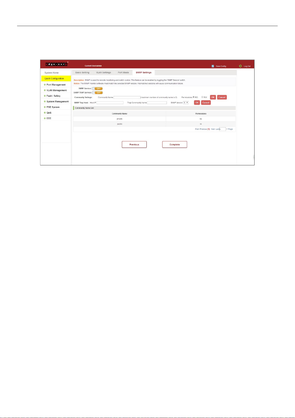
3.4 SNMP CONFIGURATION
Click "Quick Configuration" and then "SNMP Settings" to access the SNMP Settings page. You can configure SNMP
settings, such as enable/disable SNMP and SNMP TRAP services, etc. When configuration is complete, click "Next".
Figure 3-4: SNMP Settings
13
Page 14
4 PORT MANAGEMENT
4.1 BASIC SETTINGS
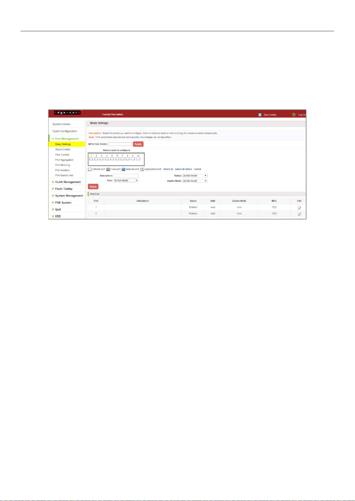
4.1.1 Check the port configuration
On the navigation bar, click "Port Management" and then "Basic Settings" to view the current configuration of the
switch ports:
Figure 4-1: Port List Information
The port list attributes show the current switch port configuration information:
1. Port: The number of the port.
2. Port Description: Displays the switch port description.
3. Port Status: The switch port status information; enabled or disabled.
4. Port Rate: Displays the switch port speed configuration; auto-negotiation or 10/100/1000.
5. Working Mode: Displays the switch port duplex configuration; auto-negotiation, full, or half duplex.
6. MTU: Indicates the maximum size of packets on the port.
14
Page 15

4.1.2 Configuring port properties
Click the icon to configure the selected port attributes:
Figure 4-2: Port Properties Configuration
Configure port properties as follows:
Step 1: Click the "Edit" icon .
Step 2: In the Port Properties configuration page, fill/select the value to be configured.
Step 3: Click the "Apply" button to complete the configuration.
4.2 STORM CONTROL
4.2.1 Check the storm control port settings
On the navigation bar, click "Port Management" and then "Storm Control" to view the current switch port storm
control information.
Figure 4-3: Storm Control List Information
15
Page 16

The list of ports shows the current storm control property values:
1. Port: The number of the port.
2. Unknown-unicast: Unknown unicast packets control.
3. Broadcast: Broadcast packet control.
4. Unknown-multicast: Multicast packets control.
5. When the control value setting is not a multiple of 16, the system automatically matches the closest multiple of
16.
6. The control values of unknown-unicast, broadcast, and unknown-multicast, can only be a single value.
Clicking the corresponding port on the port panel selects the port to be configured.
Figure 4-4: Configuring Storm Control Information
You can also select multiple ports for batch settings.
Figure 4-5: Bulk Edit Configuration Information
16
Page 17

After selecting the ports in the Storm Control port panel, set the unknown-unicast, unknown-multicast, and
broadcast values. For example, set the port 1 unknown-unicast storm control to 1009, and then click "Apply
Settings".
Figure 4-6: Configuring Storm` Control Information
The configuration displays as shown below:
Figure 4-7: Configuration Successfully Storm Control Information Flow Control
4.3 FLOW CONTROL
Click "Port Management" and then "Flow Control" to view the port flow control information on the switch.
Figure 4-8: Flow Control Information
17
Page 18

4.3.1 Configuring flow control
To enable the port flow control function: Select the ports to enable traffic control, and then click "Flow Control".
Select "On" and click "Apply".
Figure 4-9: Open Port Flow Control Function
To enable port traffic control, follow these steps:
Step 1: Select the port.
Step 2: Set the "Flow control" to “On”.
Step 3: Click "Apply".
View the port list to check that the configuration is successful:
Figure 4-10: Port Flow Control Status
18
Page 19

To modify the port flow control function: Click on the port traffic control list corresponding to the rear port of the
" " button in the Port Settings page "Flow Control Type" select "Off", "Apply Settings":
Figure 4-11: Close the Port Flow Control
Close port traffic control, follow these steps:
Step 1: Select the button to the right of the port or directly selected port;
Step 2: In the "Flow Control Type" select off;
Step 3: Click "Apply".
4.4 PORT AGGREGATION
4.4.1 Viewing port aggregation configuration
Click "Port Management" "Port Aggregation" to view the current switch configured port aggregation information:
Figure 4-12: Aggregation Port Configuration Information
19
Page 20

In the port aggregation list which shows the current switch port configuration information for the polymerization
properties:
1. Aggregation number: display link aggregation group number value;
2. Load Balancing: Displays the current link aggregation group load balancing judgment condition;
3. Aggregate types: Displays whether to use a polymerization port LACP protocol;
4. Member ports quantity: Displays the number of ports in the link aggregation group contains a total of member
port: Displays the current port link aggregation group member prompt
5. Each aggregate port can bind up to eight member ports, port to transfer data among members of the network
traffic through the shunt rules.
6. Port aggregation group must ensure that the port speed, duplex, port state agreement, or can not ATTACH after
configuration.
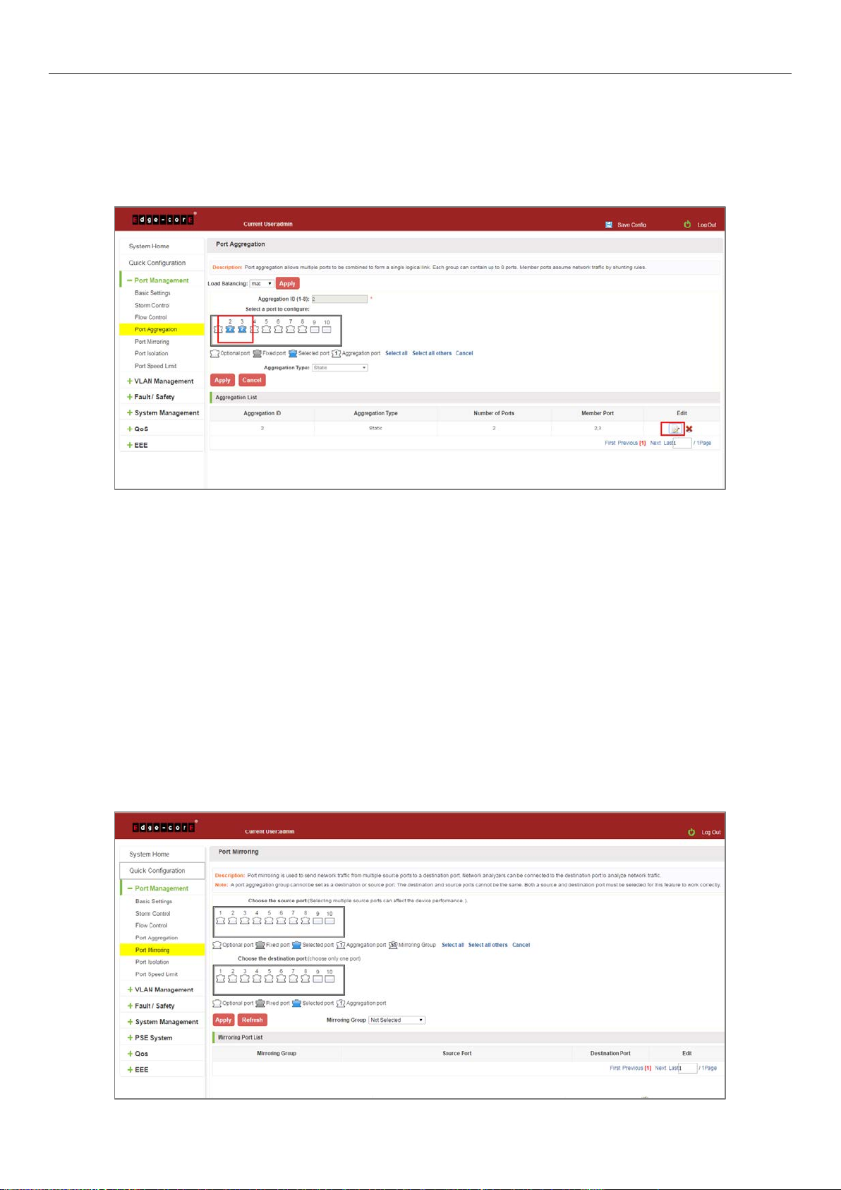
4.4.2 Add port aggregation
Enter aggregation port number, select the desired aggregation port, select aggregation type, click "Apply".
Figure 4-13: Port Aggregation Configuration Area
Increase port aggregation, follow these steps:
Step 1: Select the option to load the shunt in the load balancing list.
Step 2: Enter the number in the "Aggregation number" in.
Step 3: Select the aggregated ports in the panel.
Step 4: Select the aggregation type.
Step 5: Click the "Apply" button to complete the configuration.
20
Page 21
4.4.3 Modifying port aggregation
Click on "Aggregation List" in the need to modify the port aggregation right icon in this area to the port aggregation
port aggregation group corresponding modification:
Figure 4-14: To Modify the Port Aggregation
Modify Link Aggregation Procedure:
Step 1: In the "Aggregation List Click to modify the right of the port aggregation,
Step 2: In the port aggregation configuration page to modify the load balancing type and click Next to "Apply".
Step 3: Select the port to be added to the aggregation port.
Step 4: Click the "Apply" button to complete the configuration.
4.5 PORT MIRRORING
4.5.1 Port mirroring configuration
Click "Port Management" "Configuration of Port Mirroring "Port Mirroring" view of the switch:
21
Page 22

Figure 4-15: Port Mirroring Configuration Information
In the Port Mirroring is a property list which shows the configuration of the current mirror switch:
Mirroring group: mirroring group ID, can be configured up to seven mirroring group;
Source Port: The port forwarding on the source data is mirrored to the destination port;
Destination port: mirror data sent to the destination port.
1. Port aggregation port can not be used as the destination port and source port;
2. Destination port and source port can not be the same;
3. Same group mirroring group can have only one destination port.
4.5.2 Add port mirroring group
On the panel, select "Source Port" and "Destination Port" add port mirroring group.
Figure 4-16: Add Port Mirroring Group
Figure 4-17: Add Port Mirroring Group Results
22
Page 23

Port mirroring configuration steps are as follows:
Step 1: Select "Source Port",
Step 2: Select "Destination Port",
Step 3: select mirroring group,
Step 4: Click "Apply".
Configuration instructions:
1. On the switch can be configured 7 mirroring group.
2. Aggregated port mirroring can not be configured are shown in gray in the panel.
3. Has been selected port mirroring port, displayed in the faceplate is gray.
4. Aggregated port mirroring can not be configured are shown in gray in the panel.
5. Has been selected port mirroring port, displayed in the faceplate is gray.
4.5.3 To modify the port mirroring group
Select the group to modify, click on the action bar " " button. Modify the corresponding mirroring group.
Figure 4-18: To Modify the Port Mirroring Group
Modify the port mirroring configuration steps are as follows:
Step 1: In the image you want to modify the operation of the group column, click on " ";
Step 2: Add or remove the corresponding port in the panel;
Step 3: Click "Apply".
23
Page 24

4.5.4 Delete a port mirroring group
Figure 4-19: Delete Port Mirroring Group
Figure 4-20: Deleted Successfully Port Mirroring
Remove port mirroring configuration steps are as follows:
Step 1: In the image you want to modify the operation of the group column, click " ";
Step 2: In the panel, click Cancel the source port, destination port and then click Cancel;
Step 3: In the panel, click Cancel the source port, destination port and then click Cancel;
Step 4: Click "Apply".
24
Page 25

4.6 PORT ISOLATION
4.6.1 Port isolation configuration
Click "Port Management" "Configuration of Port Mirroring "Port Isolation" view of the switch:
Figure 4-21: Port Isolation Configuration Information
4.6.2 Configuring port isolation
Open Port Isolation function: select the port on which you want to open port isolation, click the "Port Isolation Type"
Select "On", "Apply".
Figure 4-22: Enable Port Isolation Function
25
Page 26

4.6.3 Modify the port isolation
Figure 4-23: Enable Port Isolation Results
Select the port to modify, click on the action bar " " button. Modify the corresponding port isolation.
Figure 4-24: To Modify the Port Isolation
26
Page 27

4.7 PORT SPEED LIMIT
4.7.1 View port rate limit
Click "Port Management" "Port Speed Limit" switch to view the current port speed configured information:
Figure 4-25: View Rate Configuration Information
In the port speed list which shows the current speed limit switch attribute configuration information:
Port: The number of the port;
Input limit: uplink port speed;
Output speed: port downstream rate;
4.7.2 Configure port access rate
Select the panel to set the speed limit of the port, set the rate limit value by dragging the speed bar.
Figure 4-26: Configure Port Rate Limiting Entrance
27
Page 28

Figure 4-27: Port Entrance Speed Limit Results
Entrance port rate limiting configuration steps are as follows:
Step 1: Click on the right side of the port " " Icon or select multiple icons;
Step 2: Set rate limiting strip port value;
Step 3: Click the lower right corner "Apply" button to complete the configuration.
4.7.3 Remove the port speed limit
Click the need to remove the limit on the right port icon '' in the configuration area of the port rate value pull bar to
the far right, "Apply" to complete the operation.
Figure 4-28: Remove the Port Speed Limit
Remove uplink port rate limiting steps are as follows:
Step 1: Click on the right side of the port icon;
Step 2: In the area of the port rate configuration value rate strip pulled to the far right;
Step 3: Click the "Apply" button to complete the configuration.
28
Page 29

5 VLAN MANAGEMENT
5.1 VLAN MANAGEMENT
5.1.1 Check VLAN configuration information
Click on the navigation bar "VLAN Management" "VLAN Management" "VLAN Settings" to view the switch
configured:
Figure 5-1: VLAN Configuration Information
In the VLAN list which shows the properties of the configuration information of the current switch VLAND:
1. VLAN ID: VLAN ID value is displayed;
2. VLAN Name: The name of the VLAN, the default VLAN ID to name;
3. VLAN IP address: Displays the switch's management IP;
4. Port: Displays the port VLAN that exist.
5. By default, all ports belong to VLAN 1.
29
Page 30

5.1.2 Adding a VLAN
Click "New VLAN" button, you can increase the VLAN configurations:
Figure 5-2: Adding a VLAN
Adding a VLAN, follow these steps:
Step 1: Click "New VLAN" connection;
Step 2: Value added VLAN VLAN ID of the page to fill in;
Step 3: Select the ports;
Step 4: Click the lower right corner "Apply" button to complete the configuration.
5.1.3 Remove VLAN
5.1.3.1 Single VLAN delete
To delete the selected VLAN, click the "X" button to delete the selected VLAN, if the VLAN do not have ports, you can
directly delete the VLAN; if the VLAN have some ports, you must be remove the ports in the VLAN firstly and then
you can delete the selected VLAN.
Figure 5-3: Delete a Single VLAN
30
Page 31

5.1.3.2 Delete multiple VLAN
First select the VLAN you want to be deleted before the checkbox, then click "Delete VLAN" button to delete the
selected VLAN, if the VLANs have some ports the VLAN can not be removed because of there are member ports. The
others will be removed.
Figure 5-4: Delete Multiple VLAN
Delete multiple VLAN, follow these steps:
Step 1: I want to delete VLAN check box;
setp2: Click on the bottom left "Delete VLAN" connection;
Step 3: Confirm delete.
5.1.4 Editing VLAN
5.1.4.1 VLAN port to a VLAN
Click on the icon can be added to the selected port in the VLAN:
Figure 5-5: Add the Port to the VLAN
31
Page 32

Add the port to the VLAN, follow these steps:
Step 1: Click" "icon.
Step 2: Selected to join the ports in the port panel.
Step 3: Click the lower right corner "Apply" button to complete the configuration.
5.1.4.2 To remove the port from a VLAN
Click on the icon, you can remove the port from this VLAN:
Figure 5-6: To Remove the Port from the VLAN
Procedure to remove the port from VLAN as follows:
Step 1: Click on the icon " ";
Step 2: Remove the port to be removed from the port panel;
Step 3: Click on the lower right corner of the "Apply" button to complete the configuration.
32
Page 33

5.1.5 View port mode
Click on the "VLAN Management" "Port Mode" view switches has been configured port mode information:
Figure 5-7: View Port Mode Configuration Information
Displayed in the port mode list is the property value of the port configuration of the current switch:
1. The port name: display port number used;
2. The Native VLAN: display native VLAN:
3. The allowed VLAN: the VLAN allows the display message can be through VLAN;
4. The default port is 1 VLAN native VLAN.
5. The default port mode is access.
5.1.6 Change the port mode is trunk
Select the port you want to change the mode and click the "Port Mode" list, you can set the port mode is trunk:
Figure 5-8: Change the Port Mode is Trunk
33
Page 34

The steps to set port mode is trunk are as follows:
Step 1: Chose one or more ports;
Step 2: Click the port mode list chose the mode is: trunk;
Step 3: Set Native VLAN, the VLAN must be is exist;
Step 4: Set by allowing the VLAN number, the default allowed VLAN is empty, if you want to allowed the native
VLAN, you must be configure allowed the native VLAN;
Step 5: Click on the lower right corner of the "Apply" button to complete the configuration.
5.1.7 Change the port mode is hybrid
Select the port you want to change the mode and click the "Port Mode" list, you can set the port mode is hybrid:
Figure 5-9: Change the Port Mode is Hybrid
The steps to set port mode is hybrid are as follows:
Step 1: Chose one or more ports;
Step 2: Click the port mode list chose the mode is: hybrid;
Step 3: Set Native VLAN, the VLAN must be is exist;
Step 4: Set by allowing the VLAN number, the default allowed VLAN 1, if you want to allowed the native VLAN, you
must be configure allowed the native VLAN;
Step 5: Click on the lower right corner of the "Apply" button to complete the configuration.
34
Page 35
5.2 VOICE VLAN
5.2.1 View voice VLAN information
Click on the navigation bar "VLAN Management" "Voice VLAN" "Voice VLAN Global" to view the switch configured:
Figure 5-10: View Voice VLAN Information
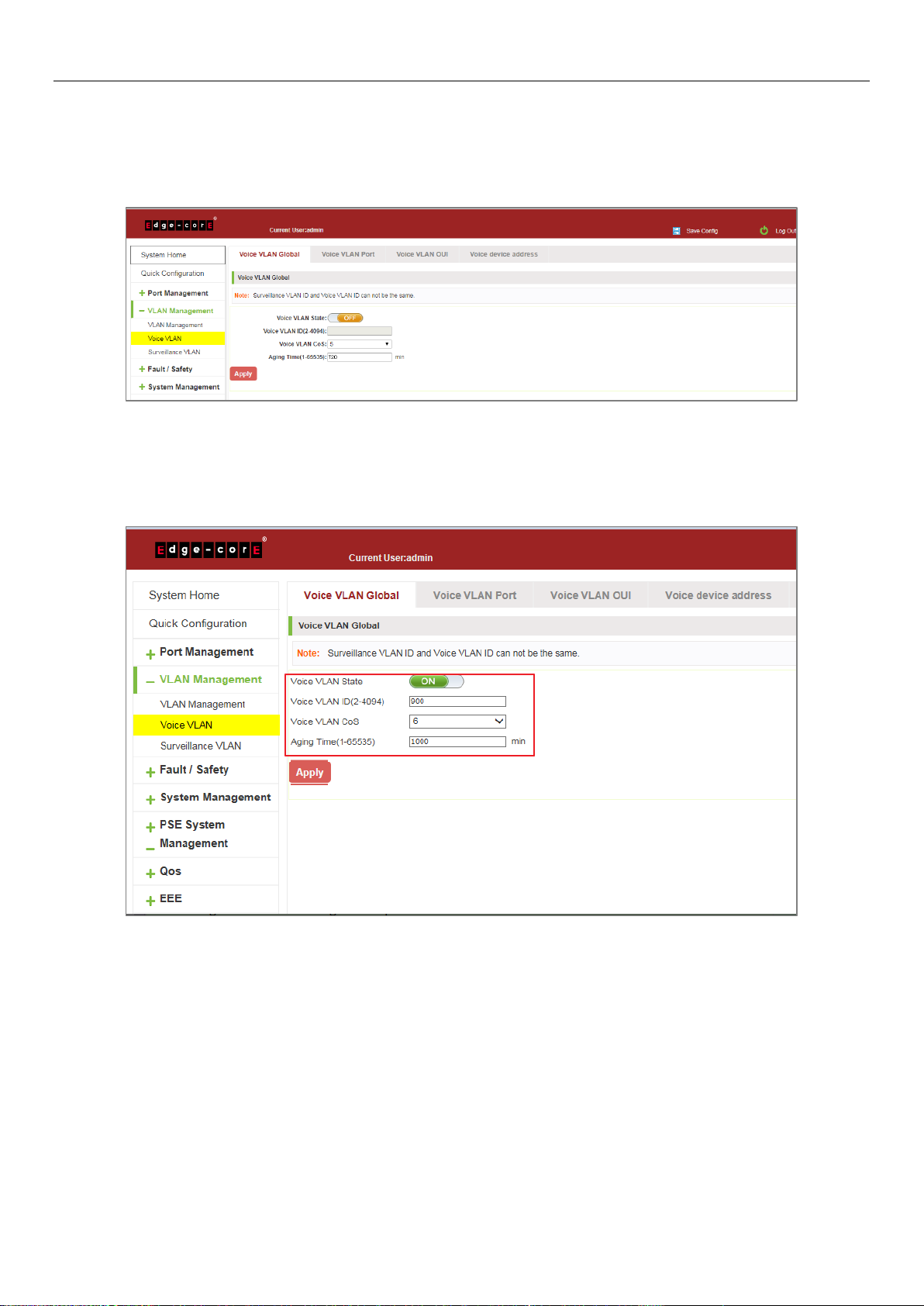
5.2.2 Configure voice VLAN global
Click on the navigation bar "VLAN Management" "Voice VLAN" "Voice VLAN Global" to configure the voice VLAN;
Figure 5-11: View Voice VLAN Information
To configure the voice VLAN global steps as follows:
Step 1: In the voice VLAN state TEXT BOX, click ON the "OFF" to "ON",
Step 2: In the voice VLAN ID text box, enter the ID, such as 900;
Step 3: In the voice VLAN COS text box, choose 6;
Step 4: In the aging time text box, enter aging time, such as 1000;
Step 5: Click "Apply".
35
Page 36

5.2.3 Configure voice VLAN port
Click on the navigation bar "VLAN Management" "Voice VLAN" "Voice VLAN port" to configure the voice VLAN port;
Figure 5-12: Configure Voice VLAN Port
To configure the voice VLAN port steps as follows:
Step 1: Select ports to configure,
Step 2: In the state text box, choose enable;
Step 3: In the mode text box, choose manual;
Step 4: Click "Apply".
5.2.4 Configure voice VLAN OUI
Click on the navigation bar "VLAN Management" "Voice VLAN" "Voice VLAN OUI" to configure the voice VLAN OUI;
Figure 5-13: Configure Voice VLAN OUI
36
Page 37

To configure the voice VLAN OUI steps as follows:
Step 1: In the OUI address text box, enter OUI address, such as 00-b0-1E-00-00-00;
Step 2: In the mask text box, enter the mask, such as FF-FF-FF-00-00-00;
Step 3: In the description text box, enter the description, such as testOUI;
Step 4: Click "Apply".
5.2.5 Voice device address
Click on the navigation bar "VLAN Management" "Voice VLAN" "Voice Device Address" to view the voice device:
Figure 5-14: Voice VLAN Address
5.3 SURVEILLANCE VLAN
5.3.1 View surveillance VLAN information
Click on the navigation bar "VLAN Management" "Surveillance VLAN" "Surveillance VLAN" to view the switch
configured:
Figure 5-15: Surveillance VLAN Information
37
Page 38

5.3.2 Configure surveillance VLAN
Click on the navigation bar "VLAN Management" "Surveillance VLAN" "Surveillance VLAN" to configure the switch
surveillance VLAN.
Figure 5-16: Configure Surveillance VLAN
To configure the surveillance VLAN steps as follows:
Step 1: In the surveillance VLAN TEXT BOX, click ON the "OFF" to "ON",
Step 2: In the surveillance VLAN ID text box, enter the ID, such as 500;
Step 3: In the surveillance VLAN COS text box, choose 3;
Step 4: In the aging time text box, enter aging time, such as 500;
Step 5: Click "Apply".
5.3.3 MAC settings and surveillance device
Click on the navigation bar "VLAN Management" "Surveillance VLAN" "Surveillance VLAN" "MAC Settings and
Surveillance Device" to configure the user-defined MAC settings.
Figure 5-17: Configure the User-defined MAC Settings
38
Page 39

To configure the surveillance VLAN steps as follows:
Step 1: In the component type EXT BOX, choose video management server;
Step 2: In the description text box, enter testOUI;
Step 3: In the MAC address text box, enter MAC address, such as 00A1.0203.0000.
Step 4: In the mask text box, enter the mask, such as FFFF.F000.000,
Step 5: Click "Apply".
5.3.4 MAC settings and surveillance device
Click on the navigation bar "VLAN Management" "Surveillance VLAN" "Surveillance VLAN" “
MAC Settings and Surveillance Device" to view the information:
Figure 5-18: Configure the User-defined MAC Settings
39
Page 40

6 FAULT/SAFETY
6.1 ATTACK PREVENTION
6.1.1 ARP snooping
6.1.1.1 View ARP configuration
Click the "Fault/Safety" "Attack Prevention" "ARP Inspection" to check the current switches has been configured for
ARP information, this feature is turned off by default.
Figure 6-1: View Port ARP Inspection Information
6.1.1.2 ARP inspection function
In the ARP Inspection configuration, enable this function and then selected a port to configure some parameters.
Click the "Save" button to complete the configuration.
Figure 6-2: ARP Inspection Configuration
40
Page 41

Figure 6-3: Change ARP Inspection Configure
Figure 6-4: Change ARP Inspection Configure Success
6.1.1.3 Disable ARP inspection function
In the ARP Inspection configuration table, click the button from on to off to disable the ARP Inspection and then click
the "OK" button to complete the configuration.
Figure 6-5: Disable ARP Inspection Function
41
Page 42

6.1.2 Port security
6.1.2.1 Configuration port security
Click the "Fault/Safety" "Attack prevention" "Port Security", configure the switch port security:
Figure 6-6: Port security configuration
In the configuration page, selected one or more ports, enable the admin state and configure the port max learning
address. Then, click "Save" button.
Figure 6-7: Port Security Manual Configuration
42
Page 43

6.1.2.2 Change port security status
In the port list, select the port to edit, change the some parameters or disable the port security and click the button
of "Save".
Figure 6-8: Change Port Security Status
6.1.3 DHCP snooping
6.1.3.1 View DHCP snooping configuration
Click the "Fault/Safety" "Attack Prevention" "DHCP Snooping", the configuration information show the anti DHCP
attack:
Figure 6-9: View Anti DHCP Snooping Configuration Information
43
Page 44

Display refresh configuration information.
6.1.3.2 Open DHCP snooping function
Click on a "Fault/Safety" "DHCP Snooping" click the button to open the DHCP snooping:
Figure 6-10: Activation of DHCP Snooping Function
6.1.3.3 Set the port to DHCP snooping trusted port
In the trusted port list, select the port that needs to be disabled to prevent DHCP attacks, and click the "Apply"
button and enable option82 function.
Figure 6-11: Disable Anti-Illegal DHCP Server Functions and Enable Option 82
The activation of anti DHCP attack function, is the port setting for trust status;
Disable - preventing DHCP attack, is set to a non-trusted state port.
44
Page 45

6.1.3.4 The trusted port gets the IP address
Click "Binding List" to view the list information.
Figure 6-12: View the IP Address that the Trusted Port Gets
6.1.3.5 Configure CID information
Click the "Option82 Circuit ID" button, configure the CID information:
Figure 6-13: CID Information
45
Page 46

6.1.3.6 Off DHCP snooping function
Click the "ON" button, will prevent the DHCP attack function off:
Figure 6-14: Off DHCP Snooping Function
6.1.4 CPU Guard
Click the "Fault/Safety" "Attack prevention" "CPU Guard", the configuration information show the CPU guard.
Figure 6-15: CPU Guard Information
46
Page 47

Change CPU guard configuration:
Figure 6-16: Change CPU Guard Configuration
6.2 PATH DETECTION
6.2.1 Path/Tracert detection
Click the "Fault/Safety" "Path Detection" or "Tracert Detection" can view the Path Detection configuration:
Figure 6-17: Path Detection Information
47
Page 48

6.2.2 Cable detection
Figure 6-18: Tracert Detection Information
Click the "Fault/Safety" "Path Detection" "Cable Detection" can view the Cable Detection configuration:
Figure 6-19: Cable Detection Information
48
Page 49

The cable detection only selected one port:
Figure 6-20: Port Cable Detection Result
6.3 PORT ERROR DISABLE
Collect port disable information, and can set the port auto recovery time.
Figure 6-21: Error Disable Automatic Recovery Configuration
49
Page 50

6.4 DDOS PROTECTION
Click the "Fault/Safety" "DDOS Protection" can view the DDOS protection configuration:
Figure 6-22: DDOS Protection Information
Selected dos type to prevent multiple computers from sending attack packets.
Figure 6-23: Selected DoS Type
50
Page 51

6.5 LOOP DETECTION
Click the "Fault/Safety" "Loop Detection" can view the current loop detection configuration:
Figure 6-24: View Loopback Detection Configuration Information
6.5.1 Enable loopback detection
Enable the loopback detection and configuration some parameters, click "Apply" button:
Figure 6-25: Enable Loopback Detection
51
Page 52
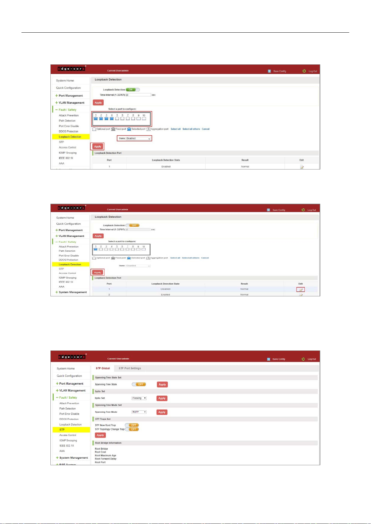
6.5.2 Choose the port to configure
Selected one or more ports to change the loopback detection status:
Figure 6-26: Configure Ports Parameter
Click "Edit" button, change the port status:
Figure 6-27: Change the Port Configure
6.6 STP
Click the "Fault/Safety" "STP" "STP Global" can view the current STP global configuration:
Figure 6-28: STP Global View
52
Page 53

6.6.1 Enable STP function
Enable STP global state and configuration mode and traps.
Notice:
1. When the loopback detection and STP functions are mutually exclusive.
2. LLDP PDU flooding enabled prevents executing mSTP enable.
6.6.2 STP port settings
Selected port to configuration STP.
Figure 6-29: Enable STP Change Mode and Traps
Figure 6-30: Selected Port to Configuration STP
53
Page 54

6.7 ACCESS CONTROL
6.7.1 ACL access control list
6.7.1.1 View access control list
Click the "Fault/Safety" "Access Control" you can view the configuration information of the access control list:
Figure 6-31: Access Control List
6.7.1.2 Increased access rules
1. INCREASE THE STANDARD IP ACCESS RULES
Click "New ACL Rules", in the pop-up dialog box, select "Standard IPV4 ACL Configuration", in the list of ID:0, ID:0
ACE, rules to allow. IP address is: any source IP address. Click "Apply" to complete the new rules:
Figure 6-32: Configuration Standard IP Access Control List
54
Page 55

2. INCREASE THE EXTENDED IP ACCESS RULE
Click "New ACL Rules", in the pop-up dialog box, select "Configuration Expand IP ACL", in the list of ACE, ID:0 ID:10,
rules for "Permit". Agreement: TCP, source IP address: any source IP address; purpose IP address: any destination IP
address, click "Apply" to complete the new:
Figure 6-33: Configuration Standard IP Access Control List
3. INCREASING EXPAND MAC ACCESS RULES
Click "New ACL rules", select "Configuration Expand MAC ACL" in the pop-up window, in list ID: 20,ACE ID: 0, Rules
"Deny", Source MAC address: 0088.9999.999A. Destination MAC address is the random MAC. MAC protocol type:
0x0086. After the configuration is complete, click "Apply":
Figure 6-34: Configuration Extended MAC Access Control List
Configuration instructions
ACE ID is an optional rule. Do not fill: the default is 0;
The extended IP protocol access control list, type: TCP, UDP, IP.
55
Page 56

6.7.1.3 Modify configuration
Rules for modifying port applications
Select the rules to be replaced, click " ", enter the modified ACL rules page, the rules are: "Deny", click "Apply":
Figure 6-35: To Modify the ACL Rule
Configuration instructions
The modified extended MAC and extended IP for the same operation.
6.7.1.4 Delete rule
To delete the rule, click "X" to delete the current list of ACE under a ACL rule:
Figure 6-36: Delete Rules
56
Page 57

Remove all of the ACE rule table under a ACL, click "Delete":
Figure 6-37: Delete ACL Rules
Configuration instructions
Delete - after the success of the kneeling in port configuration table deleted together.
6.7.2 Application ACL
6.7.2.1 View application ACL
The configuration information and click on the "Fault/Safety" "Access Control" "Apply ACL" can view access control
using ACL:
Figure 6-38: View Application ACL Rules
57
Page 58

6.7.2.2 Increased application ACL
Select the rules that need to be applied, then select the port of application, click "Apply" to complete the
configuration:
Figure 6-39: Add Applications ACL
6.7.2.3 Delete application ACL
Click to delete the application rule on the right side, cancel the application of the rules in the port:
Figure 6-40: Delete Application ACL
58
Page 59

6.8 IGMP SNOOPING
6.8.1 IGMP snooping
6.8.1.1 View IGMP snooping configuration
Click the "Fault/Safety" "IGMP Snooping" to check the current switch configured multicast monitoring information:
Figure 6-41: View Snooping IGMP Configuration Information
6.8.1.2 Action multicast listener function
Click the "Fault/Safety" "IGMP Snooping", click "Off" button to activate the multicast monitoring function:
Figure 6-42: Open Multicast Listener Configuration
The default multicast listener (IGMP Snooping) did not open;
The default on multicast listener (IGMP Snooping), all VLAN are open;
The default version of V2 - IGMP.
59
Page 60

6.8.1.3 Disable multicast listener function
Click the "Fault/Safety" "IGMP Snooping", click "ON" button to disable multicast monitoring function:
Figure 6-43: Closed Multicast Listener Function Operation
6.8.1.4 Configuration multicast routing
Select VLAN, click "Router Port Add" button, to configure the multicast routing in the port panel:
Figure 6-44: Configuration of Multicast Routing
Multicast routing configuration steps are as follows:
Step 1: In the port panel to select multicast listener routing port;
Step 2: Select VLAN;
Step 3: Click on the "Add Router Port" button to complete the configuration.
60
Page 61

6.8.1.5 IGMP Version
Click the "Fault/Safety" "IGMP Snooping", set the IGMP version of the page:
Figure 6-45: Configuration IGMP Version
IGMP version configuration steps are as follows:
Step 1: Select the required version number;
Step 2: Click the "Apply" button to complete the configuration.
6.8.2 MLD
6.8.2.1 View MLD configuration
Click the "Fault/Safety" "IGMP Snooping" to check the current switch configured multicast monitoring information:
Figure 6-46: View MLD Configuration Information
61
Page 62

6.8.2.2 Active multicast listener function
Click the "Fault/Safety" "MLD", click "Off" button to activate the multicast monitoring function:
Figure 6-47: Open Multicast Listener Configuration
The default multicast listener (MLD) did not open;
The default on multicast listener (MLD), all VLAN are open;
The default version of V1 - MLD.
6.8.2.3 Disable multicast listener function
Click the "Fault/Safety" "IGMP Snooping", click "ON" button to disable multicast monitoring function:
Figure 6-48: Closed Multicast Listener Function Operation
62
Page 63

6.8.2.4 Configuration multicast routing
Select VLAN, click "Router Port Add" button, to configure the multicast routing in the port panel:
Figure 6-49: Configuration of Multicast Routing
Multicast routing configuration steps are as follows:
Step 1: In the port panel to select multicast listener routing port;
Step 2: Select VLAN;
Step 3: Click on the "Add Router Port" button to complete the configuration.
6.9 IEEE 802.1X
IEEE 802.1X is a port-based authentication protocol is a method and strategy for authenticating users.
Configure the PC 192.168.2.145, and connect with switch by Gi 0/2
Configure the radius sever 192.168.2.100, and connect with switch by Gi 0/1
Click ON "Fault/Safety" "IEEE 802.1X"
Figure 6-50: IEEE 802.1X
63
Page 64

Click to Open.
Figure 6-51: Enable IEEE 802.1X
Switch config AAA RADIUS server address: 192.168.2.100, Auth Port: 1812, Key: 123, type: all
Figure 6-52: Configuration Radius
64
Page 65

Switch enable 802.1X port Gi 0/2, Port Control: auto, Host Mode: multi-auth
Figure 6-53: Configuration IEEE802.1X
Tips: The IEEE802.1x function is used with the AAA function.
Auto: It indicates that the initial state of the port is unauthorized. It only allows EAPOL packets to be sent and
received. It does not allow users to access network resources. If the authentication passes, the port switches to the
authorized state, allowing the user to access the network resources. This is also the most common case.
Force-auth: Indicates that the port is always authorized, allowing users to access network resources without
authorization.
Force-unauth: Indicates that the port is always in an unauthorized state and does not allow the user to authenticate.
The device does not provide authentication services to clients that pass through the port.
Single-host: This port can only connect to a host, through authentication can be forwarded for data packets.
Multi-auth: This port can be connected to the following switches, including a host through the certification, other
hosts can be forwarded data packets.
Multi-host: This port can be connected to the following switches, including a host through the certification, other
host data packets can not be forwarded, must also have passed authentication.
6.10 AAA
6.10.1 RADIUS
Enabled and logged in can use radius authentication
Configure the PC 192.168.2.145, and connect with switch by Gi 0/2
Configure the radius sever 192.168.2.100, and connect with switch by Gi 0/1
Click ON "Fault/Safety" "AAA" "RADIUS"
Switch config AAA RADIUS server address: 192.168.2.100, Auth Port: 1812, Key: 123, type: all
65
Page 66

Figure 6-54: Configuration Radius
Switch config Method List: Name: test, Method 1: RADIUS, click "Apply".
Switch config Enable Authentication: Console: ECS2020, Telnet: ECS2020, SSH: ECS2020, click "Apply".
Figure 6-55: Configuration Enable Authentication
Switch config Method List: Name: ECS2020, Method 1: RADIUS, click "Save".
Switch config Enable Authentication: Console: ECS2020, Telnet: ECS2020, SSH: ECS2020, click "Save".
Figure 6-56: Configuration Login Authentication
66
Page 67

TIPS:
1. Pc input right user name and password, PC can console, telnet and ssh switch.
2. Pc input right password, user can join "# mode".
6.10.2 TACACS+
Enable and Login can use TACACS+ authentication
Configure the PC 192.168.2.145, and connect with switch by Gi 0/2
Configure the TACACS+ sever 192.168.2.100, and connect with switch by Gi 0/1
Click on "Fault/Safety" "AAA" "TACACS+"
Switch config AAA TACACS+ server address: 192.168.2.100, Auth Port: 49, Key: qwer
Figure 6-57: Configuration TACACS+
Switch config Method List: Name: ECS2020, Method 1: TACACS+, click "Save".
Switch config Enable Authentication: Console: ECS2020, Telnet: ECS2020, SSH: ECS2020, click "Save".
Figure 6-58: Configuration Enable Authentication
67
Page 68

Switch config Method List: Name: ECS2020, Method 1: TACACS+, click "Apply".
Switch config Enable Authentication: Console: ECS2020, Telnet: ECS2020, SSH: ECS2020, click "Apply".
Figure 6-59: Configuration Login Authentication
You can successfully open AAA TACACS+ function
PC input right user name and password, PC can console, telnet and SSH switch
PC input right password, user can join "# mode".
68
Page 69

7 SYSTEM MANAGEMENT
7.1 SYSTEM SETTINGS
7.1.1 Management VLAN
7.1.1.1 Configuration basic system settings
Click on the navigation bar "System Management" "System Settings" "Management VLAN" to view the management
address of the current switch configuration information:
Figure 7-1: Basic System Settings
To configure the switch Basic System Settings as follows:
Management VLAN: switch management VLAN ID, the default is 1
1. In the DHCP text box, choose static allocation
2. In the Management IP text box, enter the IP address, such as 192.168.2.10
3. In the Subnet Mask text box, enter the subnet mask, such as 255.255.255.0
4. In the Gateway Address text box to enter the gateway address, such as 192.168.2.1
5. In the Device Location text box, enter the Device Location, such as china
6. In the Contact Name text box, enter the Contact Name, such as john
7. In the Contact Information text box, enter Contact Information, such as 12345678900
8. Click on "Apply" button to complete the configuration
69
Page 70

7.1.1.2 System time synchronization
Figure 7-2: System Time Synchronization
To configuration system time, You can select NTP or SNTP, enter SNTP/NTP Server IP Address such as
203.117.180.36(local SNTP/NTP servers or internet SNTP/NTP servers), in the Time Zone (T) text box, you can choose
any time zone you want, such as UTC+08:00
The user can manually configure the device system time.
70
Page 71

7.1.2 System restart
Click on the navigation bar "System Management" "System Settings" "System Restart" to reboot the switch:
Figure 7-3: System Restart
Restart the device, follow these steps:
Step 1: Click on "Restart the device immediately" button;
Step 2: Click OK in the box that pops up "OK" button;
Step 3: Prompted to save the current configuration, depending on your need to select "OK" or "Cancel";
Step 4: After the restart the progress bar moves to 100%, reboot the device.
7.1.3 User Management
Click on the navigation bar "System Management" "System Settings" "User Management" to modify the super user
password and telnet password:
Figure 7-4: Change Password
71
Page 72
To change the password follow these steps:
Step 1: Enter the old password: password;
Step 2: Enter the new password: admin;
Step 3: Confirm new password: admin;
Step 4: Click the "Apply" button;
Step 5: Pop-up dialog box, click "OK" button.
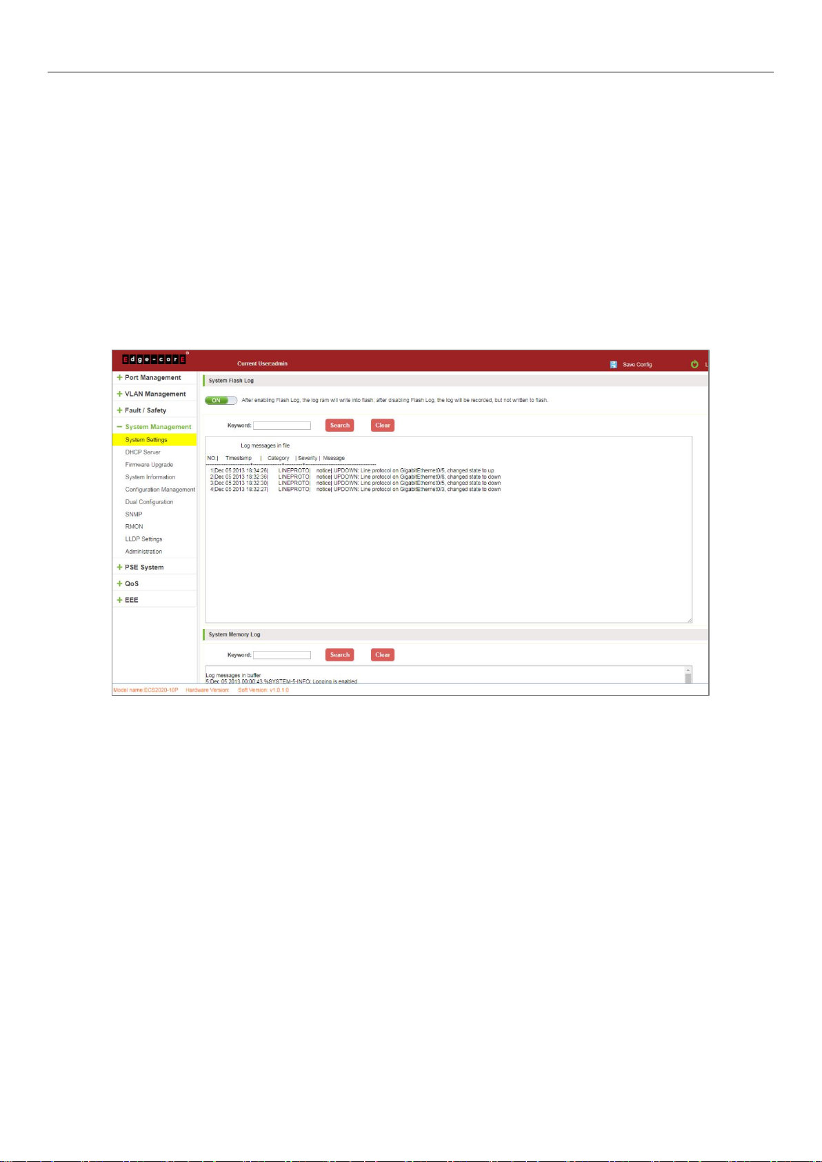
7.1.4 System log
Click on the navigation bar "System Management" "System Settings" "System Log" to enter the log management
interface, you can query the system log, clear the log:
Figure 7-5: System Log
Log management system WEB page to view the contents of the command line is consistent with the results of the
command show logging; Click "Clear" button to clear the current log information switch.
72
Page 73
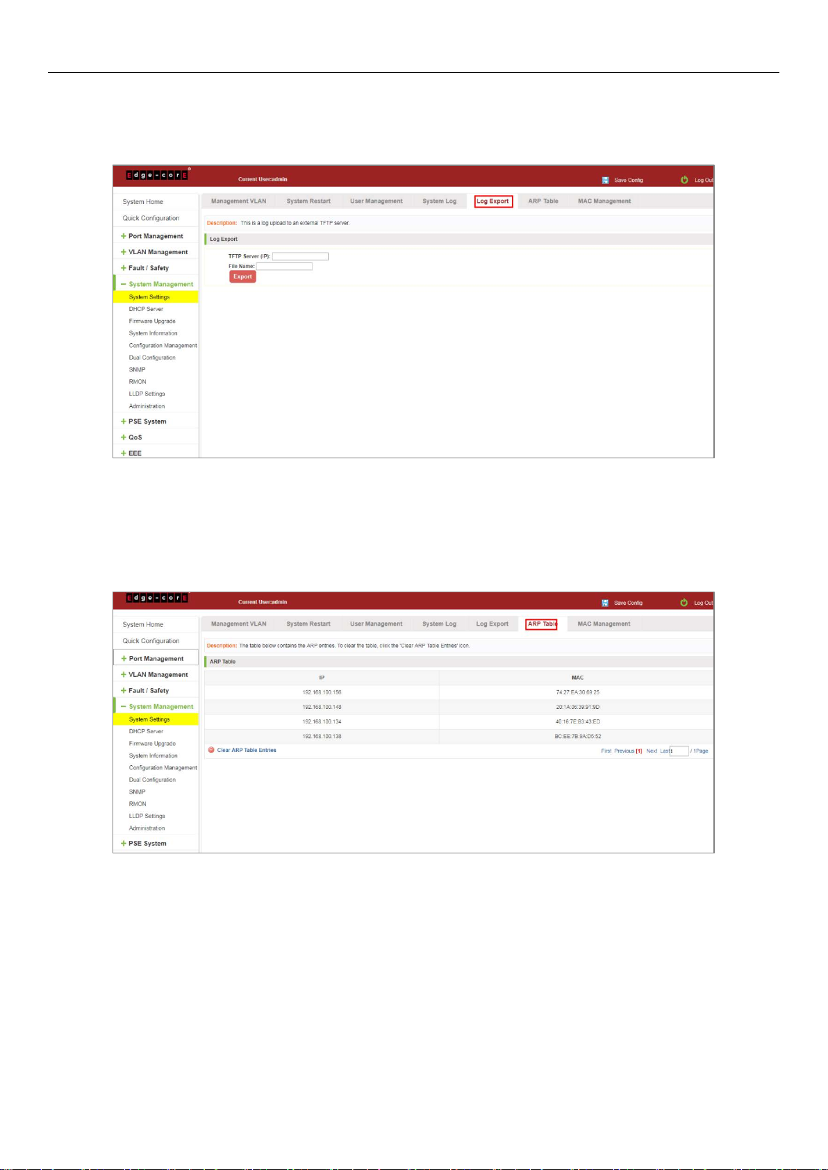
7.1.5 Log export
Click on the navigation bar "System Management" "System Settings" "Log Export" to export log information into the
interface, you can export the log information through TFTP server.
Figure 7-6: Log Export
7.1.6 ARP table
Click on the navigation bar "System Management" "System Settings" "ARP Table" to enter the ARP entry interface,
you can view the ARP information:
Figure 7-7: ARP Message
Click "Clear ARP table entries" button to clear the display ARP information.
73
Page 74

7.1.7 MAC management
7.1.7.1 MAC address lookup
Click the "System Management" "System Settings" "MAC Management" can switch MAC address information query:
Figure 7-8: MAC address Lookup Display
In the MAC address list which shows the current switch port to learn MAC addresses:
1. User MAC: MAC address of the switch that currently exists is displayed;
2. Port: Displays the source port number of the MAC address;
3. Port Type: There are two types of dynamic and static;
4. VLAN: VLAN ID display value.
You can query the MAC address type: according to the type of query MAC address, type in the MAC address MAC
check list next to the drop-down box Select: All/static/dynamic.
7.1.7.2 Add a static MAC address type
1. Use manual binding MAC address
Click the "Configure MAC Binding" After, you can configure a static MAC address type in the MAC address
configuration area:
74
Page 75

Figure 7-9: MAC Addresses Statically Bound Static Configuration
Statically typed MAC address configuration steps are as follows:
Step 1: Click the "Configure MAC Binding" button;
Step 2: In the "User MAC" text box to enter the MAC address, such as 0001.7A4F.74D2;
Step 3: In the "VLAN ID" text box to enter the VLAN ID, such as 1;
Step 4: Select ports in the port panel;
Step 5: Click on "Apply" to complete the configuration.
2. Use" " button binding static MAC address
In the MAC address list, select the MAC address to be bound, click on the left " " button, to achieve binding:
Figure 7-10: MAC Address of the Static Binding Configuration
75
Page 76

3. Using the "Dynamic MAC to Static MAC" link Bulk Bind static MAC
In the MAC address list by checking the front of the column you want to bind, "√" check box, click on the "Dynamic
MAC to Static MAC" button to complete the configuration:
Figure 7-11: Batch-MAC Binding Configuration
7.1.7.3 Remove the static MAC address type
1. Single MAC records are deleted
Select the need to delete the MAC address, click the "X" button to delete a static MAC address type:
Figure 7-12: MAC Address Deletion
Remove MAC address configuration steps are as follows:
Step 1: To delete the selected MAC address;
Step 2: Click " " button to delete the configuration.
76
Page 77

2. Batch delete a static MAC address
In the MAC address list by checking the front of the column you want to bind, "√" check box, click "Delete Static
MAC" button:
Figure 7-13: MAC Address Batch Deletion
3. Delete all dynamic MAC address
In the MAC address list, click "Delete Dynamic MAC" button to clear all dynamic mac address:
Figure 7-14: Clear All Dynamic MAC Address
77
Page 78

7.2 DHCP SERVER
7.2.1 DHCP server info
Click the "System Management" "DHCP Server" to view the DHCP Server configuration:
Figure 7-15: DHCP Server Info
7.2.2 Enable the DHCP server
Enable the DHCP server, address pool IP range and device IP must be the same network segment IP:
Figure 7-16: Enable DHCP Server
When the host and the device are connected directly, the IP assigned to the DHCP server will be displayed in the
DHCP server client list.
78
Page 79

7.3 SYSTEM UPGRADE
Click the "System Management" "System Upgrade" to upgrade the software on the switch:
Figure 7-17: Switch System Upgrade
Switch system upgrade steps are as follows:
Step 1: Click "Choose File" button to select the switch upgrade file;
Step 2: Click the "Upgrade" button switch to start the upgrade new software;
Step 3: When the upgrade progress bar is at 100%, the switch will automatically reboot, completion of the upgrade is
completed.
7.4 SYSTEM INFORMATION
7.4.1 Memory information
Click on the "System Management" "System Information" "of" the Memory Information into the Memory
Information interface, can view the System Memory Information:
Figure 7-18: System Memory Information
79
Page 80

View the WEB page of memory information content consistent with the results show the memory command
command line; Click on the "Refresh" button to Refresh the current switches in the memory information.
7.4.2 CPU information
Click on the "System Management" "System Information" "CPU Information" to enter the CPU Information interface,
can view the System task Information:
Figure 7-19: CPU Information
Web pages to the content of the system task view consistent with the results show the CPU commands command
line; click on the "Clear" button to remove the current switches in the system; click on the "Refresh" button to
refresh the current switches in the system task.
7.5 CONFIGURATION MANAGEMENT
7.5.1 Configuration management
1. To see the current configuration
Click on "System Management" "Configuration Management" "Configuration Management", and click the button
"View of the current Configuration", View the current Configuration information:
80
Page 81

2. Save the current configuration
Figure 7-20: View the Current Configuration
Click on the "System Management" "Configuration Management" "Configuration Management", click "Save" button,
the running - the content of the config files saved to the startup --config file:
Figure 7-21: To Save the Current Configuration
81
Page 82

3. The configuration
Click on the "System Management" "Configuration Management" "Configuration Management", select "Import
Configuration", click "Choose File" button to find Configuration File to Import, click the "Import Configuration"
button, complete the Configuration Import:
Figure 7-22: Imported Configuration
Import the configuration steps are as follows:
Step 1: Select the "Import Configuration";
Step 2: Click "Choose File" button to find you want to import the configuration File;
Step 3: Click on "Import Configuration" button;
Step 4: Confirm the restart.
4. Export configuration
Click on the "System Management" "Configuration Management" "Configuration Management", select "Export
Configuration", export configuration.
Figure 7-23: Export Configuration
82
Page 83
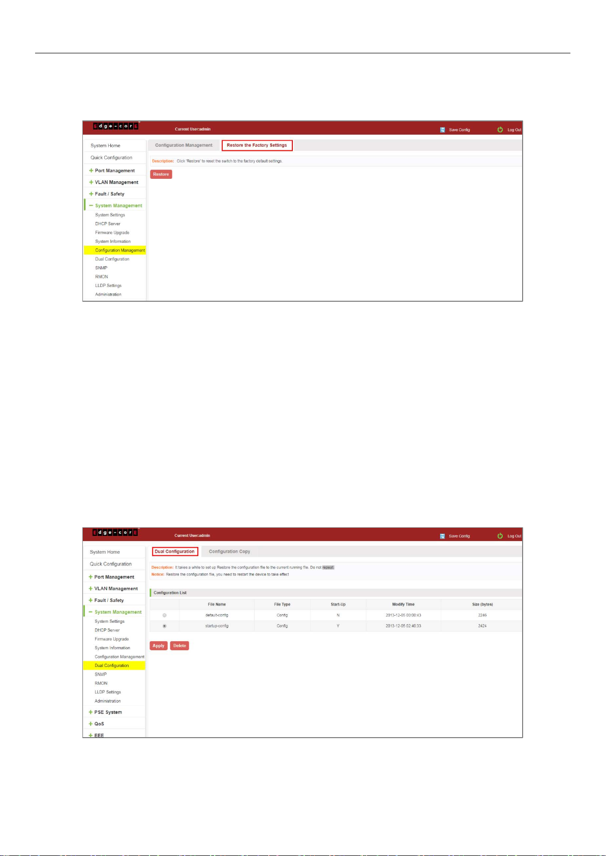
7.5.2 Restore factory settings
Click on the "System Management" "Configuration Management" "Restore the Factory Settings" to switch to Restore
the Factory Configuration actions:
Figure 7-24: Restore Factory Settings
Factory default operation steps are as follows:
Step 1: Click the "Restore the Factory Settings" button;
Step 2: In the pop-up confirmation box, click the "OK" button;
Step 3: After the completion of the reset switch, wait for equipment to restart, switch back to factory default
configuration.
7.6 DUAL CONFIGURATION
7.6.1 Backup and restore the current configuration file
Click on "System Management" "Dual Configuration".
83
Page 84

1. Configure some functions, such as: IP address, port speed limit, port mirroring and other functions.
84
Page 85

2. Click on the "System Management" "Dual configuration". To configure the switch backup the current running
profile.
3. On the basis of step 1, add or remove the function configuration, such as: port description.
4. Click on the "Apply"/"Delete". The configuration file is applied, the system will set the parameters to run at
system startup; can also delete the configuration file.
85
Page 86

7.6.2 Configuration Copy
Back up the running-config file to the startup-config file or backup-config file.
Figure 7-25: Configuration copy
7.7 SNMP
7.7.1 Check the SNMP
Click on the "System Management" "SNMP", you can view the SNMP configured information:
Figure 7-26: View the SNMP Configuration Information
By default SNMP is not open;
SNMP monitoring software and switches the SNMP version is consistent, if inconsistencies can lead to
communication failure.
86
Page 87

7.7.2 Activate the SNMP
Click ON the "System Management" "SNMP", choose the SNMP service, click ON the "OFF" to "ON", click ok:
Figure 7-27: Activation SNMP Function
Activation function SNMP configuration steps are as follows:
Step 1: Choose open SNMP options;
Step 2: Click "OK" button to complete the configuration.
7.7.3 To disable the SNMP
Click ON the "System Management" "SNMP", choose the SNMP service, click ON the "ON" to "OFF", complete the
configuration:
Figure 7-28: Disable the SNMP Function
Disable the SNMP function configuration steps are as follows:
Step 1: Choose close SNMP options;
Step 2: Click "OK" button to complete the configuration.
87
Page 88

7.7.4 Activate the TRAP
After open the SNMP, select the SNMP TRAP service, click ON the "OFF" to "ON", click ok:
Figure 7-29: Activation Function of the TRAP
Activate the TRAP function configuration steps are as follows:
Step 1: Select "ON" option;
Step 2: Click "OK" button to complete the configuration.
7.7.5 Disable the TRAP
Choose the SNMP TRAP service, click ON the "ON" to "OFF", click "OK", complete the configuration:
Figure 7-30: Disable TRAP Function
Disable the TRAP function configuration steps are as follows:
Step 1: Select "ON" to "OFF" option;
Step 2: Click "OK" button to complete the configuration.
88
Page 89

7.7.6 Change community
Click on the "System Management" "SNMP", in the community name text box input: public, permissions choice: read
and write, click the "OK" button, complete the configuration:
Figure 7-31: Change Community
Change community configuration steps are as follows:
Step 1: In the community name dialog box input: the pub;
Step 2: Select "RO" permissions;
Step 3: Click on "OK" button, complete the configuration.
7.7.7 Added the SNMP TRAP service host
Click on the "System Management" "SNMP", in the host IP text box input: 192.168.100.150, TRAP community name:
pub, SNMP version choice: 2C, click the "OK" button, complete the configuration:
Figure 7-32: Increases the SNMP TRAP Service Host
89
Page 90

Increase the SNMP TRAP service host configuration steps are as follows:
Step 1: In the host IP dialog box input: 192.168.100.150;
Step 2: In TRAP community name dialog input: pub;
Step 3: Select the SNMP version: 2C;
Step 4: Click on "OK" button, complete the configuration.
When an SNMP closed, hide the SNMP TRAP service host list.
7.7.8 Delete the SNMP TRAP service host
Click on the "System Management" "SNMP", in the SNMP TRAP service host list need to delete the object, click
"" " finish configuration:
Figure 7-33: Delete Community
7.8 RMON
7.8.1 View ROMN configure information
Click on the "System Management" "RMON", can view RMON configure information.
Figure 7-34: View RMON Configure Information
90
Page 91

7.8.2 Configure ROMN type
Configure ROMN type: Alarm, selected one port to configure and setting parameters and click "Apply" button.
Figure 7-35: Configure ROMN Type
Notice: Parameters There are some special rules in the configuration. The EVENT should be created first. Please note
the prompts in the configuration. eg: Rising Threshold is greater than Falling Threshold.
7.8.3 Change ROMN type
On the ROMN configure page, click the type "Event" or "History" and setting parameters. Be careful the parameter
of Community should be exit in SNMP Community name. Configure ok after clicking "Apply".
Figure 7-36: Change ROMN Type is Event
91
Page 92

Figure 7-37: Change ROMN Type is History
When the parameters configure is ok, click the Statistics List. We can choose the port to view the information.
Figure 7-38: View the Port Configure Information
7.8.4 Delete the configured rule
Select the entry you want to delete and click Fork to delete the unwanted configuration
Figure 7-39: Delete the Alarm List Rule
92
Page 93

Figure 7-40: Delete the Event List Rule
Figure 7-41: Delete the History List Rule
7.9 LLDP SETTINGS
7.9.1 LLDP settings
Click on the "System Management" "LLDP Settings", "LLDP Settings" can view the LLDP settings information. The
default mode is Global settings and this feature is turned off by default.
Figure 7-42: View LLDP Settings Information
93
Page 94

7.9.2 Enable LLDP settings
Click the drop-down menu to select enable and configuration parameters. Finally click "Apply" button.
Figure 7-43: Enable LLDP settings
7.9.3 LLDP PORT SET
Configuration the LLDP Port Properties:
Figure 7-44: LLDP port properties
7.9.4 Neighbor info
When the LLDP function is enabled, the neighbor information is recorded when a neighbor device is found. Notice:
you should be configuration the Peer device on CLI, on the port of the peer device that is connected to the DUT:
LLDP tlv-select sys-name sys-cap.
94
Page 95

7.10 ADMINISTRATION
7.10.1 Telnet info
Figure 7-45: Neighbor Info
Click on the "System Management" "Administration, "Administration Settings" can view the telnet settings
information. This feature is turned off by default.
Figure 7-46: Telnet Info
95
Page 96

7.10.2 ENABLE THE TELNET
Click on the button " " and apply .To enable the telnet, and the user can connect to the device via telnet.
Figure 7-47: Enable Telnet
Figure 7-48: Telnet Login
96
Page 97

7.10.3 HTTPS
Enable https function, users can through https management the device.
Figure 7-49: Enable HTTPS
Figure 7-50: HTTPS login
97
Page 98
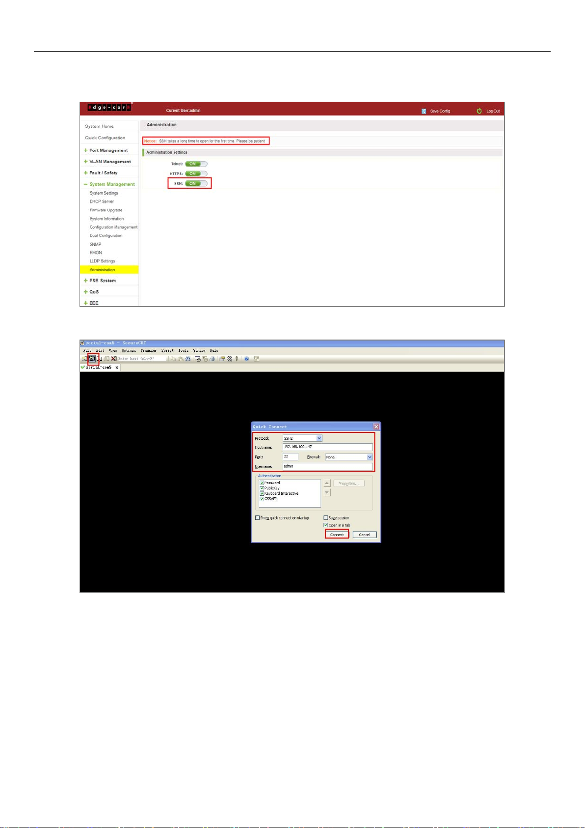
7.10.4 SSH
Enable SSH function and SSH takes a long time to open for the first time.
Figure 7-51: Enable SSH
98
Page 99

Figure 7-52: Use SSH2 Login
99
Page 100

Figure 7-53: Use SSH1 Login
100
 Loading...