

Page 1

s
ECG9210-04
Home Gateway VDSL2
Router with 802.11b/g
capabilities
User Guide
http://www.edgecorenetworks.com
http://www.edgecorenetwork
Page 2

Page 3

User Guide
Home Gateway VDSL2 Router
VDSL2 Home Gateway Router with
4100BASE-TX (RJ-45) Ports, 2 VDSL Ports (RJ-11)
and 802.11b/g wireless capabilities
Page 4

EGC9210-04
E022010-DT-R01
150200000095A
Page 5

Compliances
FCC - Class B
This equipment has been tested and found to comply with the limits for a Class B
digital device, pursuant to Part 15 of the FCC Rules. These limits are designed to
provide reasonable protection against harmful interference in a residential installation.
This equipment generates, uses and can radiate radio frequency energy and, if not
installed and used in accordance with instructions, may cause harmful interference to
radio communications. However, there is no guarantee that the interference will not
occur in a particular installation. If this equipment does cause harmful interference to
radio or television reception, which can be determined by turning the equipment off
and on, the user is encouraged to try to correct the interference by one or more of the
following measures:
• Reorient the receiving antenna
• Increase the separation between the equipment and receiver
• Connect the equipment into an outlet on a circuit different from that to which the
receiver is connected
• Consult the dealer or an experienced radio/TV technician for help
You are cautioned that changes or modifications not expressly approved by the party
responsible for compliance could void your authority to operate the equipment.
You may use unshielded twisted-pair (UTP) for RJ-45 connections - Category 3 or
better for 10 Mbps connections, or Category 5 or better for 100 Mbps connections.
This device complies with Part 15 of the FCC Rules. Operation is subject to the
following two conditions: (1) This device may not cause harmful interf erence, and (2)
this device must accept any interference received, including interference that may
cause undesired operation.
For product available in the USA/Canada market, on ly channel 1~11 can be operated.
Selection of other channels is not possible.
This device and its antenna(s) must not be co-located or operation in conjunction with
any other antenna or transmitter.
IMPORTANT NOTE:
FCC Radiation Exposure Statement:
This equipment complies with FCC radiation exposure limits set forth for an
uncontrolled environment. This equipment should be installed and operated with
minimum distance 20cm between the radiator & your body.
EC Conformance Declaration
Marking by the above symbol indicates compliance with the Essential Requirements of the
R&TTE Directive of the European Union (1999/5/EC). This equipment meets the following
conformance standards:
• EN 60950-1 (IEC 60950-1) - Product Safety
v
Page 6

• EN 300 328 - Technical requirements for 2.4 GHz radio equipment
• EN 301 489-1 / EN 301 489-17 - EMC requirements for radio equipment
This device is intended for use in the following European Community and EFTA countries:
Austria Belgium Cyprus Czech Republic Denmark
Estonia Finland France Germany Greece
Hungary Iceland Ireland Italy Latvia
Liechtenstein Lithuania Luxembourg Malta Netherlands
Norway Poland Portugal Slovakia Slovenia
Spain Sweden Switzerland United Kingdom
Requirements for indoor vs. outdoor operation, license requirements and allowed channels
of operation apply in some countries as described below:
• In Italy the end-user must apply for a license from the national spectrum authority to
operate this device outdoors.
• In Belgium outdoor operation is only permitted using the 2.46 - 2.4835 GHz band:
Channel 13.
• In France outdoor operation is only permitted using the 2.4 - 2.454 GHz band:
Channels 1 - 7.
Note: The user must use the configuration utility provided with this product to ensure the
channels of operation are in conformance with the spectrum usage rules for
European Community countries as described below.
• This device will automatically limit the allowable channels determined by the current
country of operation. Incorrectly entering the country of operation may result in illegal
operation and may cause harmful interference to other systems. The user is obligated to
ensure the device is operating according to the channel limitations, indoor/outdoor
restrictions and license requirements for each European Community country as described
in this document.
• This device may be operated indoors only in all countries of the European Community
using the 2.4 GHz band: Channels 1 - 13, except where noted below.
• In Italy the end-user must apply for a license from the national spectrum authority to
operate this device outdoors.
• In Belgium outdoor operation is only permitted using the 2.46 - 2.4835 GHz band:
Channel 13.
• In France outdoor operation is only permitted using the 2.4 - 2.454 GHz band:
Channels 1 - 7.
Declaration of Conformity in Languages of the European Community:
Czech
Česky
Estonian
Eesti
SMC tímto prohlašuje, že tento Radio LAN device je ve shodě se základními
požadavky a dalšími příslušnými ustanoveními směrnice 1999/5/ES.
Käesolevaga kinnitab SMC seadme Radio LAN device vastavust direktiivi
1999/5/EÜ põhinõuetele ja nimetatud direktiivist tulenevatele teistele
asjakohastele sätetele.
vi
Page 7

English Hereby, SMC, declares that this Radio LAN device is in compliance with the
essential requirements and other relevant provisions of Directive 1999/5/
EC.
Finnish
Suomi
Dutch
Nederlands
French
Français
Swedish
Svenska
Danish
Dansk
German
Deutsch
Greek
Ελληνική
Hungarian
Magyar
Italian
Italiano
Latvian
Latviski
Lithuanian
Lietuvių
Maltese
Malti
Valmistaja SMC vakuuttaa täten että Radio LAN device tyyppinen laite on
direktiivin 1999/5/EY oleellisten vaatimusten ja sitä koskevien direktiivin
muiden ehtojen mukainen.
Hierbij verklaart SMC dat het toestel Radio LAN device in overeenstemming
is met de essentiële eisen en de andere relevante bepalingen van richtlijn
1999/5/EG
Bij deze SMC dat deze Radio LAN device voldoet aan de essentiële eisen
en aan de overige relevante bepalingen van Richtlijn 1999/5/EC.
Par la présente SMC déclare que l'appareil Radio LAN device est conforme
aux exigences essentielles et aux autres dispositions pertinentes de la
directive 1999/5/CE
Härmed intygar SMC att denna Radio LAN device står I överensstämmelse
med de väsentliga egenskapskrav och övriga relevanta bestämmelser som
framgår av direktiv 1999/5/EG.
Undertegnede SMC erklærer herved, at følgende udstyr Radio LAN device
overholder de væsentlige krav og øvrige relevante krav i direktiv 1999/5/EF
Hiermit erklärt SMC, dass sich dieser/diese/dieses Radio LAN device in
Übereinstimmung mit den grundlegenden Anforderungen und den anderen
relevanten Vorschriften der Richtlinie 1999/5/EG befindet". (BMWi)
Hiermit erklärt SMC die Übereinstimmung des Gerätes Radio LAN device
mit den grundlegenden Anforderungen und den anderen relevanten
Festlegungen der Richtlinie 1999/5/EG. (Wien)
με την παρουσα SMC δηλωνει οτι radio LAN device συμμορφωνεται προσ
τισ ουσιωδεισ απαιτησεισ και τισ λοιπεσ σχετικεσ διαταξεισ τησ οδηγιασ
1999/5/εκ.
Alulírott, SMC nyilatkozom, hogy a Radio LAN device megfelel a vonatkozó
alapvetõ követelményeknek és az 1999/5/EC irányelv egyéb elõírásainak.
Con la presente SMC dichiara che questo Radio LAN device è conforme ai
requisiti essenziali ed alle altre disposizioni pertinenti stabilite dalla direttiva
1999/5/CE.
Ar šo SMC deklarē, ka Radio LAN device atbilst Direktīvas 1999/5/EK
būtiskajām prasībām un citiem ar to saistītajiem noteikumiem.
Šiuo SMC deklaruoja, kad šis Radio LAN device atitinka esminius
reikalavimus ir kitas 1999/5/EB Direktyvos nuostatas.
Hawnhekk, SMC, jiddikjara li dan Radio LAN device jikkonforma mal-ħtiġijiet
essenzjali u ma provvedimenti oħrajn relevanti li hemm fid-Dirrettiva 1999/
5/EC.
vii
Page 8

Spanish
Español
Polish
Polski
Portuguese
Português
Slovak
Slovensky
Slovenian
Slovensko
Por medio de la presente SMC declara que el Radio LAN device cumple con
los requisitos esenciales y cualesquiera otras disposiciones aplicables o
exigibles de la Directiva 1999/5/CE
Niniejszym SMC oświadcza, że Radio LAN device jest zgodny z
zasadniczymi wymogami oraz pozostałymi stosownymi postanowieniami
Dyrektywy 1999/5/EC.
SMC declara que este Radio LAN device está conforme com os requisitos
essenciais e outras disposições da Directiva 1999/5/CE.
SMC týmto vyhlasuje, že Radio LAN device spĺňa základné požiadavky a
všetky príslušné ustanovenia Smernice 1999/5/ES.
SMC izjavlja, da je ta radio LAN device v skladu z bistvenimi zahtevami in
ostalimi relevantnimi določili direktive 1999/5/ES.
Customer Information
1. This equipment complies with Part 68 of the FCC rules and the requirements
adopted by the ACTA. On bottom of this equipment is a label that contai ns,
among other information, a product identifier of [INSERT LABEL]. If requested,
this number must be provided to the telephone company.
2. If this equipment, ECG9210-04, causes harm to the telephone network, the
telephone company will notify you in advanc e that temporary discontinuance of
service may be required. But if advance notice isn't practical, the telephone
company will notify the customer as soon as possible. Also you will be advised of
your right to file a complaint with the FCC if you believe it is necessary.
3. The telephone company may make changes i n its facili ties, equipment, op erations
or procedures that could affect the operation of the equipment. If this happ ens, the
telephone company will provide advance notice in order for you to make
necessary modification to maintain uninterrupted service.
4. If you experience trouble with this equipment, you disconnect it from the network
until the problem has been corrected or until you are sure that the equipment is
not malfunctioning.
5. Please follow instructions for repairing if any (e.g. battery replacement section);
otherwise do not alternate or repair any parts of device except specified.
6. Connection to party line service is subject to state tariffs. Contact the state public
utility commission, public service commission or corporation commission for
information.
7. If your home has specially wired alarm equipment connected to the telephone
line, ensure the installation of this equipment does not disable alarm equipment,
consult your telephone company or a qualified installer.
viii
Page 9

Warnings and Cautionary Messages
Warning: This product does not contain any serviceable user parts.
Caution: Do not plug a phone jack connector in the RJ-45 port. This may damage this
Caution: Use only twisted-pair cables with RJ-45 connectors that conform to FCC
device.
standards.
Environmental Statement
The manufacturer of this product endeavours to sustain an environmentally-friendly policy
throughout the entire production process. This is achieved though the following means:
• Adherence to national legislation and regulations on environmental production standards.
• Conservation of operational resources.
• Waste reduction and safe disposal of all harmful un-recyclable by-products.
• Recycling of all reusable waste content.
• Design of products to maximize recyclables at the end of the product’s life span.
• Continual monitoring of safety standards.
End of Product Life Span
This product is manufactured in such a way as to allow for the recovery and disposal of all
included electrical components once the product has reached the end of its life.
Manufacturing Materials
There are no hazardous nor ozone-depleting materials in this product.
Documentation
All printed documentation for this product uses biodegradable paper that originates from
sustained and managed forests. The inks used in the printing process are non-toxic.
ix
Page 10

x
Page 11

About This Guide
Purpose
This guide details the hardware features of the Gateway, including its physical and
performance-related characteristics, and how to install the Gateway. It also includes
information on how to operate and use the management functions of the Gateway.
Audience
The guide is intended for use by network administrators who are responsible for installing
and setting up network equipment; consequently, it assumes a basic working knowledge
of LANs (Local Area Networks).
Conventions
The following conventions are used throughout this guide to show information:
Note: Emphasizes important information or calls your attention to related features or
instructions.
Caution: Alerts you to a potential hazard that could cause loss of data, or damage the
system or equipment.
Warning: Alerts you to a potential hazard that could cause personal injury.
Revision History
This section summarizes the changes in each revision of this guide.
January 2010 Revision
This is the first revision of this guide.
xi
Page 12

xii
Page 13

Contents
Chapter 1: Introduction 13
Overview 13
VDSL Technology 14
Features and Benefits 15
Description of Hardware 16
Chapter 2: Installation 25
Installation Overview 25
Package Contents 25
System Requirements 25
Cable Connections 26
Powering On 27
Configuring the TCP/IP Protocols 27
Chapter 3: Network Planning 29
Application Examples 29
Networking Concepts 29
Route Determination 29
Bridging 29
Routing 30
Network Applications 30
Accessing a Remote Site 30
Accessing the Internet 31
Network Services 32
DHCP Service 32
DNS Service 32
NAT Functions 32
Virtual Server 33
User-Definable Application Sensing Tunnel 33
DMZ Host Support 33
Security 33
Virtual Private Network 34
Chapter 4: Initial Configuration 35
Accessing the Setup Wizard 35
Using the Setup Wizard 36
Chapter 5: System Configuration 45
Using the Web Interface 45
Home Page 46
Advanced Settings Menu 47
Status Information 50
System Information 50
xiii
Page 14

Contents
WAN Status 51
Bridge WAN Status 52
LAN Status 52
System Log 53
DHCP Client List 53
System Configuration 54
System Mode 54
System Time 56
Admin Settings 57
System Tools 58
UPnP 59
Service Settings 60
SNMP 61
DNS 63
Management IP 63
WAN Configuration 64
WAN Type 64
WAN Settings 65
Dynamic IP Address 65
Static IP Address 66
PPPoE 67
DDNS 68
LAN Configuration 69
LAN Type 69
LAN Settings 70
Switch Ports 72
Route Configuration 73
Static Routing 73
Dynamic Routing 74
Policy Routing 76
Wireless Configuration 77
WLAN Security 79
WEP Security 79
WPA2 Security 80
WPS Security 82
Access Control 84
Client List 85
NAT Configuration 86
Virtual Server 86
Port Mapping 87
DMZ 89
Firewall Configuration 90
Firewall Settings 90
IP Filtering 91
ALG Configuration 92
xiv
Page 15

Contents
Remote Control 93
Denial of Service 94
VDSL Configuration 95
VDSL Status and Rate Information 95
Performance Counters 98
SNR Information 99
DELT 100
IGMP Configuration 101
IGMP Settings 102
QoS Configuration 104
QoS Settings 104
Traffic Classification 105
DSCP to 802.1p Mapping 107
ACS Configuration 108
TR Settings 108
Appendix A: Troubleshooting 111
Diagnosing Gateway Indicators 111
If You Cannot Connect to the Internet 112
Problems Accessing the Management Interface 112
Appendix B: Cables 113
Twisted-Pair Cable and Pin Assignments 113
10BASE-T/100BASE-TX Pin Assignments 113
Straight-Through Wiring 114
Crossover Wiring 115
Cable Testing for Existing Category 5 Cable 115
RJ-11 Ports 116
Appendix C: Specifications 117
Physical Characteristics 117
Standards 118
Compliances 119
Wireless Characteristics 119
Glossary 121
Index 127
xv
Page 16

Contents
xvi
Page 17

Chapter 1: Introduction
Overview
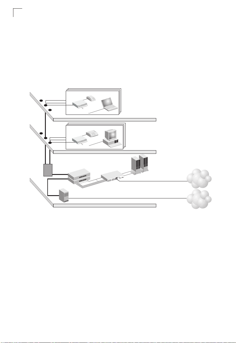
This device can serve as a key component in any Ethernet-over-VDSL2 data transport
system that consists of an end-user Gateway and a VDSL2 switch connected by
standard telephone cable. The VDSL connection delivers an Ethernet data link rated
up to both 100 Mbps downstream and 100 Mbps ups tream (VDSL2 profile 30A), while
simultaneously supporting standard telephone services. The system can be deployed
in any multi-dwelling/multi-tenant environment (apartment blocks, hotels, or office
complexes) to provide both high-speed Internet ac cess and telephone services without
any need for re-wiring. It also provides a built-in 802.11b/g access point for wireless
connectivity.
VDSL switches combine both the data and phone signals coming from your Internet
and telephone service providers, and pass these signals directly over standard
telephone wiring to multiple users in the same building. The Gateway is used to
separate these signals and pass them on to a customer’s computer and telephone
equipment.
The VDSL2 switch is typically located in a wiring closet or other cent ral location of a
multi-dwelling/multi-tenant unit, campus, or enterprise. An Internet connection is
provided from the ISP to the customer’s building over fiber optic cable, running
Ethernet directly over a 1 to 10 Gbps connection. This kind of WAN connection is
referred to as Fiber To The Building (FTTB). Data signals entering a site are first
passed through an Ethernet switch that segregates the signals for individual user
connections, and are then fed into the switch. Phone signals are also routed from PBX/
MDF distribution equipment into the switch. The data and phone signals for each user
are combined in the switch, and passed over VDSL lines to individual customers.
The Gateway at the customer end of the VDSL line connects to any PC equipped with
a 10BASE-T or 100BASE-TX network interface card. Your existing telephone, mo dem,
or fax machine simply plugs into the Gateway’s phone port. There is no need for
splitters, terminators, or filters. In fact, there is no need to modify your home wiring at
all. And because the VDSL connection is based on Ethernet, no complex software
configuration is required.
The Gateway provides access to a wide range of advanced transport features,
including support for real-time video, and other multimedia servic es requiring
guaranteed Quality of Service (QoS). It also provides multiprotocol encapsulation for
bridging Windows NetBEUI and Novell’s IPX protocols directly to a remote site for
complete access to corporate resources, or for routing TCP/IP traffic for Internet
connections.
13
Page 18
Introduction
ISP
(Internet)
Central Office
(PSTN)
Punch Down
Blocks /
Patch Panels
PBX
Telephone/Fax
Telephone
VDSL
Concentrators
Ethernet
Switch
1
E
S
3
5
2
6
F
TelephoneLine from Central Office
Fiber Optic Link to ISP
Local Servers
(Locally Hosted Services,
Video Servers, Billing)
Existing Phone
Lines to Clients
Multi-dwelling/Multi-tenant Building
Floor 2
Floor 1
Rooms/Clients
Rooms/Clients
VDSL Lines
Phone Lines
Ethernet
Links to Switch
VDSL
Gateway
VDSL
Gateway
1
VDSL Technology
VDSL (Very High Bit-Rate Digital Subscriber Line) is at the high-en d of all the DSL
technologies, offering the best combination of fiber optics and copper to provide
high-speed broadband Internet access. VDSL’s primary application is in providing a
broadband data service to multi-tenant residential or commercial buildings. In this
implementation, fiber optic cable carries the data from a telephone company’s central
office to the building; then the installed telephone copper wires take the data and
deliver it to individual units within that building.
Figure 1-1 Providing Broadband Internet Access through VDSL
VDSL provides high-speed Internet access over existing phone lin es by makin g use of
previously unused frequency bandwidth abov e the voice band (i.e., up to 30 MHz with
VDSL2). By placing VDSL signals above the frequency of the voice signal, a VDSL
service can coexist on the same line wit h o ther te lep hone servic es. VDSL c an o perat e
symmetrically, providing the same data rate in both directions, or asymmetrically,
providing a higher data rate in the downstr eam (receive) di rection than in the u pstream
(transmit) direction.
VDSL delivers high-performance online applications, such as high-quality video and
other switched multimedia services. This Ethernet VDSL2 Gateway provides robust
performance, with a data rate up to 100 Mbps downstream and 100 Mbps upstream,
and a range up to 200 meters (656 ft).
This system is based on advanced VDSL2 Multi-Carrier Modulation (MCM) technology
with adaptive channel equalization that overcomes bridge taps and other line
14
Page 19

Features and Benefits
distortions. Reed-Solomon Forward Error Correction and interleaving protects against
errors due to impulse noise, and enables recovery from signal interruptions. Frequency
Division Duplexing (FDD) separates downstream and upstream channels and allows
VDSL signals to coexist with regular telephon e se rv ice s. A p ower bac k-off mechanism
is also implemented to reduce noise from crosstalk in line bundles.
Features and Benefits
VDSL features (Gateway side) include:
• High-speed Internet access over existing phone lines
• VDSL2 connection provides the following rate/rang e options (profile 30A):
Table 1-1 Maximum Rates and Distances
Rate Mode Max. Range
100 Mbps Downstream 200 m (656 ft)
100 Mbps Upstream
• Concurrent data and telephone services over a single connection
• Always-on digital connection eliminates dial-up delays, providing transparent
reconnection when initiating a network request
• Supports ITU-T VDSL2 and interface standards
• Spectral compatibility with VDSL2, Smartphone digital PBX extensions and
narrowband interference
• Robust operation on severely distorted lines
• Supports power back-off algorithm that permits a mixed distance deployment
• Wireless 802.11b/g access point
• LEDs indicate VDSL link status, and power
• Simple plug-and-play installation
1
Additional VDSL2 features (Gateway side) include:
• Fast startup for quick initialization
• Trellis coding modulation for higher performance
• Seamless rate adaptation for enhanced quality in video applications
• Variable tone spacing enables best performance for long and short reach lines
• Improved framing, overhead channel, and interleaving
Gateway services include:
• Multiprotocol encapsulation of Windows NetBEUI, Novell’s IPX and TCP/IP via
bridging for complete access to corporate resources
• TCP/IP routing transport using RIP or RIP 2 for Internet access
15
Page 20

Introduction
1
• Network Address Translation (NAT/NAPT) which enables multiple user Internet
access with a single user account, flexible local IP address administration, and
firewall protection
• Virtual Server which allows remote users access to various services at your site
using a constant IP address
• DMZ Host allows a client to be fully ex posed to the Internet fo r applications wh ich do
not work properly behind a firewall
• Dynamic Host Configuration Protocol (DHCP) for dynamic IP address ass ignment as
a server or server relay
• TR-069 CPE WAN Management Protocol support for communication between the
Gateway and an Auto-Configuration Server
• TR-098 Multi-Service Delivery Framework for Home Networks
Description of Hardware
This Gateway is a Very High Bit-Rate Digital Subscriber Line (VDSL2) customer
premises equipment (CPE) that can connect to a remote site (via bridging) or to the
Internet (via routing). It transports data over standard telephone wire at a symmetric
data rate up to 100 Mbps downstream and 100 Mbps upstream, and a range up to
200 meters (656 ft).
This unit provides the following ports on the rear panel:
• One RJ-11 port for connection to your VDSL service provider’s incoming line.
• One RJ-11 port for connection to your telephone, modem, or fax machine. The
Gateway includes a built-in POTS voice/data splitter, so no external splitt er or
low-pass filter is required.
• Four RJ-45 ports for connection to a 10/100BASE-TX Ethernet Local Area Network.
These ports operate at 10/100 Mbps, half/full duplex. All of these ports support
automatic MDI/MDI-X operation, so you can use straight-through cables for all
network connections. (See “10BASE-T/100BASE-TX Pin Assignments,” page 113.)
• One 802.11b/g antenna for wireless connectivity.
• WPS button for instant wireless connection.
• Wall or ceiling mount kit.
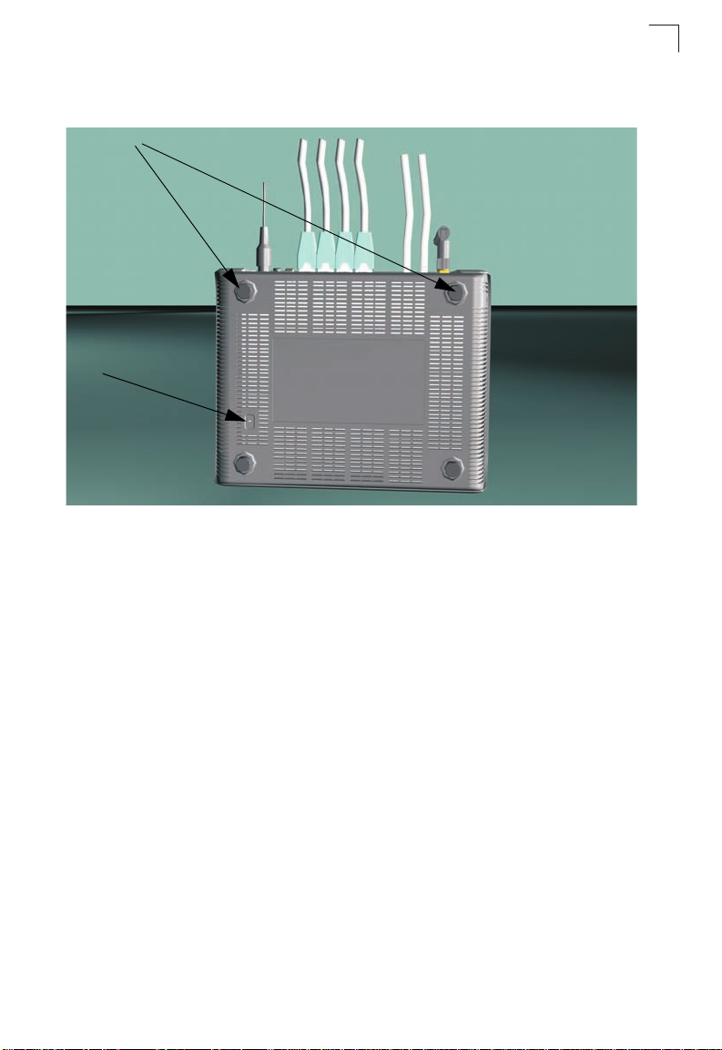
The rear panel also includes a DC p ower input jack, and a screw hole for groundi ng the
Gateway to earth.
There is also a reset button on the bottom of uni t that can be used to re store the de vice
to its factory default settings.
16
Page 21
Description of Hardware
PW
R ALARM
VDSL VD
SL LA
N
1 LAN
2 LAN
3 LAN
4 W
LAN
W
PS
LIN
K TX/RX
WPS
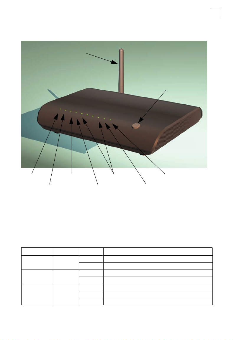
802.11b/g Antenna
WPS Button
Power LED VDSL LINK LED LAN1~4 LEDs WPS LED
ALARM LED VDSL TX/RX LED WLAN LED
The following figure shows the front components of the Gateway:
1
Figure 1-2 Top Panel
The Gateway includes key system and port indicators that simplify installation and
network troubleshooting. The LEDs, which are located on the top of the unit for easy
viewing, are described in the following table.
Table 1-2 LED Display Status
LED
Color Status Description
PWR Green On The unit is being supplied with power.
Off The unit is not receiving power.
ALARM Orange On Indicates VDSL link failure.
VDSL LINK Green On A stable link has been established with the VDSL network.
Off Connected to network; VDSL link has been established.
Off VDSL link has not been established.
Blinking The unit is synchronizing (initializing the VDSL link).
17
Page 22

Introduction
Power Receptacle Power Switch RJ-11 Phone Ports
Grounding Point RJ-45 LAN Ports
1
Table 1-2 LED Display Status (Continued)
LED
VDSL TX/RX Green On Signal detected on VDSL WAN port.
LAN1-4 Green On Ethernet link signal detected on LAN port.
WLAN Green
WPS Green
Color Status Description
Off No signal detected on VDSL WAN port.
Blinking Network traffic is crossing the VDSL WAN port.
Off No Ethernet link signal detected on LAN port.
Blinking Network traffic is crossing the LAN port.
On/
Flashing
Off Indicates the 802.11b/g radio is disabled.
On (for 10
seconds)
Fast
Flashing
Slow
Flashing
(for 10
seconds)*
Off Indicates that WPS is not in progress.
Indicates the 802.11b/g radio is enabled. Flashing indicates
wireless network activity.
Indicates the WPS authentication of a device has been
successfully completed.
Indicates the WPS authentication of a client device is in
progress.
Indicates the WPS authen tication of a device did not c omplete
after 120 seconds.
The following figure shows the rear components of the Gateway:
Figure 1-3 Rear Panel
18
Page 23
Description of Hardware
Reset Button
Rubber Feet
The following figure shows the base components of the Gateway:
Figure 1-4 Base Panel
1
19
Page 24
Introduction
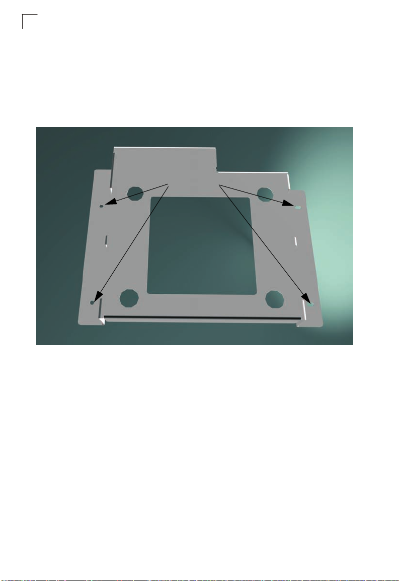
Mounting Holes
1
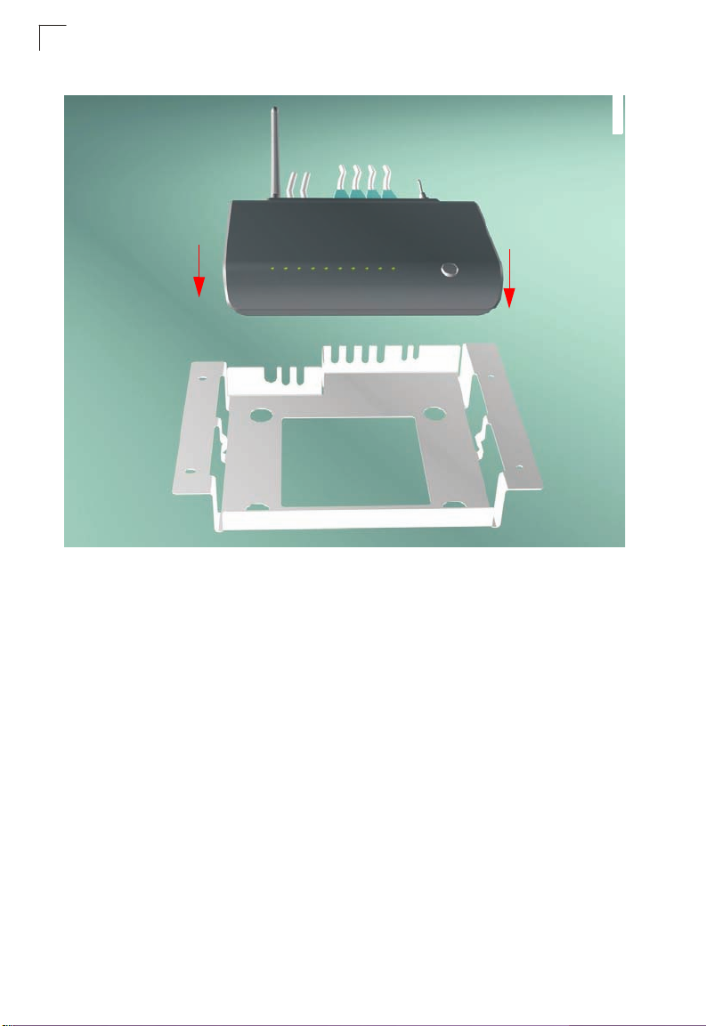
The gateway also includes a wall/ceiling mount bracket illustrated in the picture that
follows. Align the bracket in the direction indicated, marking four screw holes in the
mounting surface with a pencil. Drill four holes in the mounting surface suf ficie nt in size
to accomodate the screws that you are using. If drilling into a wall, make sure to use
wall-plugs as well.
The mounting bracket also includes two clips for attaching the unit to the backet.
Figure 1-5 Mounting Bracket - Front
Before attaching the bracket to the mounting surface be sure to connect the unit to its
required connections, a power source, RJ-11/RJ-45 leads, grounding source, and
power on the unit to make sure that it is functioning and providing connectivity.
20
Page 25

Description of Hardware
Mounting Clips
The mounting bracket also includes two clips for attaching the unit to the backet.
Figure 1-6 Mounting Bracket - Rear
1
21
Page 26
1
Introduction
Figure 1-7 Mounting the unit in the bracket
Figure 1-8
Mount the connected unit into the bracket in the direction of the red arrows shown
above, making sure the unit clips correctly into the mount ing clips.
22
Page 27
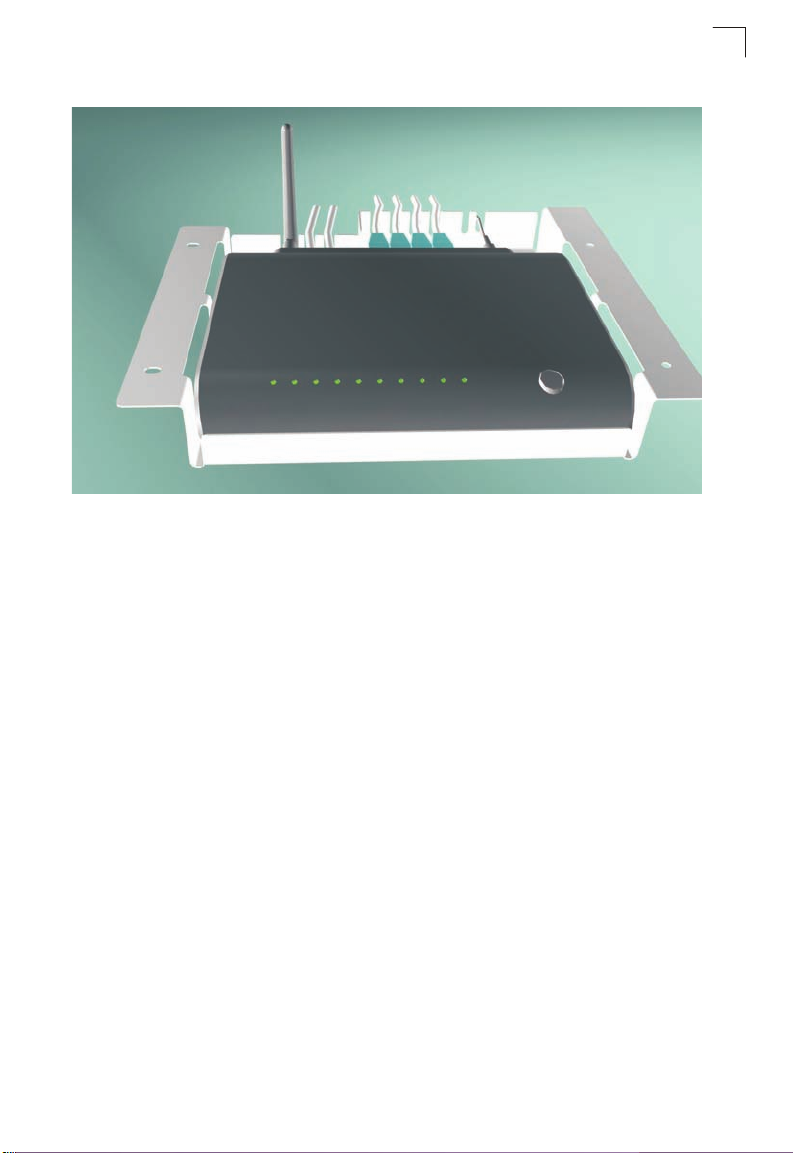
Figure 1-9 Unit in bracket
Description of Hardware
1
23
Page 28
Introduction
1
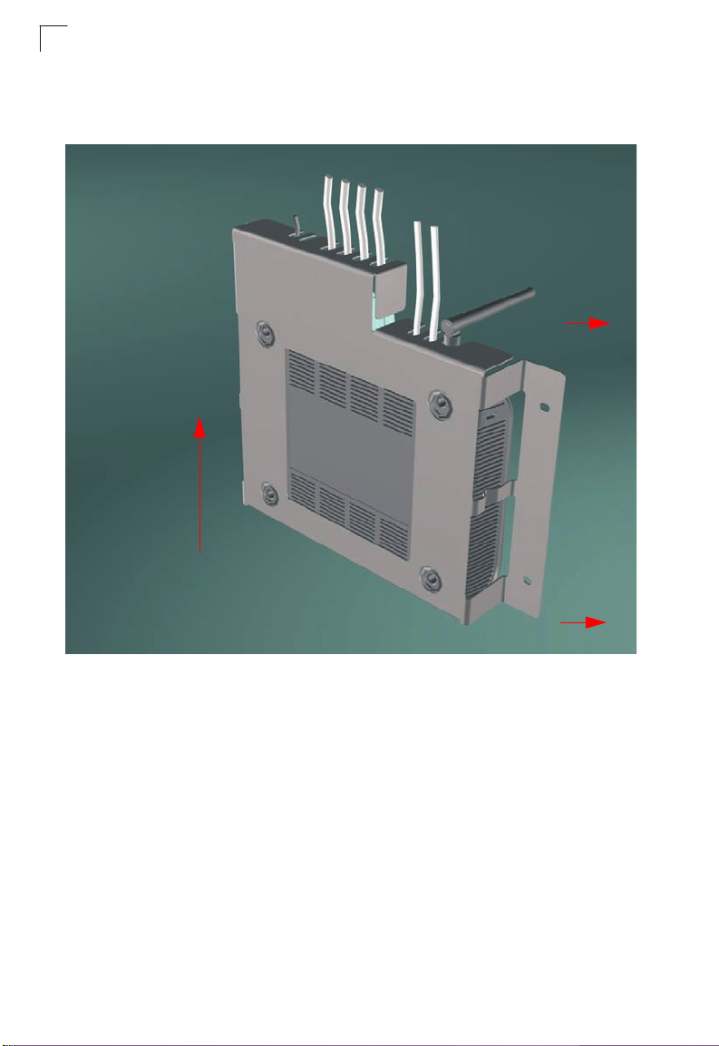
If mounting the assembled unit to a vertical surface follow the directions of the red
arrows indicated below .
24
Figure 1-10 Attaching the bracket to the mounting surface
Page 29

Chapter 2: Installation
Installation Overview
Before installing the Gateway, verify that you have all the items listed in “Package
Contents.” If any items are missing or damaged, contact your local distributor. Also,
be sure you have all the necessary tools and cabling before installing the Gateway.
Package Contents
After unpacking the Gateway, check the contents of the box to be sure that you have
received the following components:
• 1 Ethernet-over-VDSL2 Gateway
• 1 AC power adapter
• 4 rubber foot pads
• CD-ROM containing this User Guide
• 1 Category 5 UTP straight-through network cable (1 m / 3.28 ft)
• 1 standard RJ-11 telephone cable (1 m / 3.28 ft)
• Mounting bracket (Optional)
• Warranty Card
Please inform your dealer if there are any incorrect, missing, or damaged parts. If
possible, retain the carton, including the original packing materials in case there is a
need to return the Gateway for repair.
System Requirements
Before you start installing the Gateway, make sure you can provide the right operating
environment. See the following installatio n requirements:
• A PC or Macintosh with a 10/100 Mbps Ethernet adapter card inst alled.
• For Internet access, the computer must be configured for TCP/IP.
• Power requirements: 12 VDC via the included AC power adapter. Make sure that a
properly grounded power outlet is within 1.8m (6ft) of the Gateway.
• The Gateway should be located in a co ol dry place, with at least 5 cm (2 in.) of space
on all sides for ventilation.
• Place the Gateway out of direct sunlight, and away from heat sources or areas with
a high amount of electromagnetic interference. The temperature and humidity
should be within the ranges listed in the specifications.
• Be sure that the Gateway is also accessible for Ethernet and telephone cabling.
25
Page 30
Installation
Category 5 UTP cable to
Ethernet port on computer
Computer
AC Power Adapter
AC Power Outlet
RJ-11 Ports
RJ-45 Ports
VDSL Line Wall Jack
Standard Telephone Cable
Telephone, Fax, or Modem
2
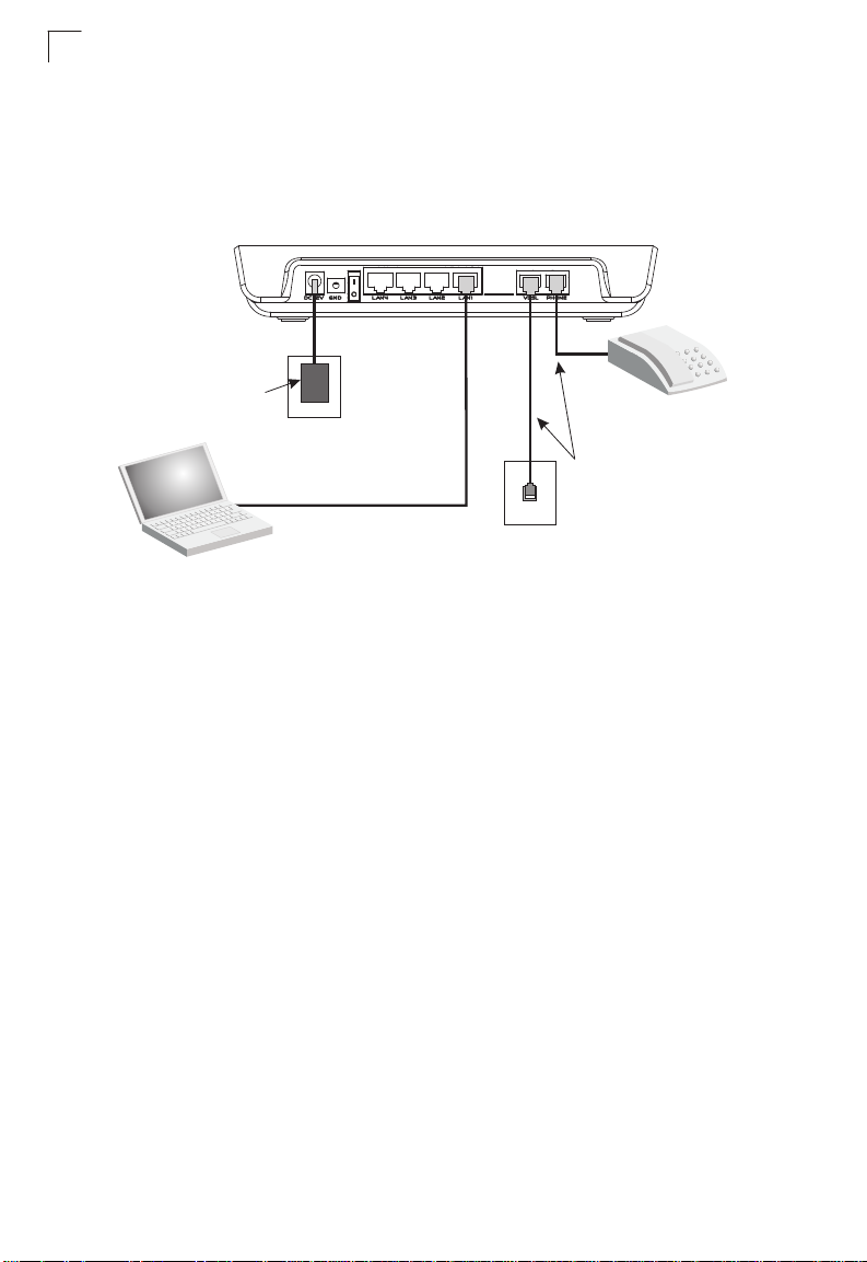
Cable Connections
Depending on the wiring configuration used in your house, sep arate wa ll jacks may be
used for telephone and VDSL services. Otherwise, you will need to connect
telephones and your computer directly to the Gateway.
Figure 2-1 Connecting the Gateway
1. Using standard telephone cable, connect the Gateway’s RJ-11 VDSL port to the
RJ-11 telephone wall jack providing the VDSL service.
2. Connect a telephone or fax machine to the RJ-11 port on the Gateway labeled
PHONE.
3. For Ethernet connections, make sure you have installed a 10BASE-T or
100BASE-TX network adapter card in the computers to be connected to the LAN.
4. Prepare straight-through shielded or unshielded twisted-pair cables with RJ-45
plugs at both ends. Use 100-Ohm Category 3, 4, or 5 cable for a 10 Mbp s Etherne t
connection, or Category 5 cable for a 100 Mbps connection.
5. Connect one end of the cable to the RJ-45 port of the network interface card, and
the other end to any of the RJ-45 LAN ports on the Gateway.
When inserting an RJ-45 plug, be sure the tab on the plug clicks into position to
ensure that it is properly seated.
Caution: Do not plug a phone jack connector into any RJ-45 port. Use only
twisted-pair cables with RJ-45 connectors that conform to FCC standards.
Notes: 1. When connecting to any network device (such as a PC, hub or switch), you can
26
use either straight-through or crossover cabling. (Refer to Appendix B: “Cables”
on page 113 for a description of cable types.)
2. Make sure the twisted-pair cable connected to any of the Gateway’s LAN ports
does not exceed 100 meters (328 feet).
Page 31

Powering On
Powering On
Plug the power adapter cord into the DC 12V power socket on the Gateway, and then
plug the power adapter directly into a power outlet. Check the LED marked PWR on
the top of the unit to be sure it is on. If the PWR indicator does not light up, refer to
Appendix A: “Troubleshooting” on page 111.
If the Gateway is properly configured, it will take about 30 seconds to establish a
connection with the VDSL service provider after powering up. During this time the
VDSL LINK indicator will flash during synchronization. After the VDSL connection has
been established, the VDSL LINK indicator will stay on.
Configuring the TCP/IP Protocols
To connect the Gateway to a computer through its Ethernet port, the computer must
have an Ethernet network adapter card installed, and be configured for the TCP/IP
protocol. Many service providers configure TCP/IP for client computers automatically
using a networking technology known as Dynamic Host Configu ration Protocol
(DHCP). Other service providers may require you to use a specific IP configuration
(known as a static IP address), which must be entered manually.
Carry out the following steps to check that the computer’s Ethernet port is correctly
configured for DHCP.
Windows 95/98/NT
1. Click “Start/Settings/Control Panel.”
2
2. Click the “Network” icon.
3. For Windows NT, click the “Protocols” tab.
4. Select “TCP/IP” from the list of network protocols; this may include details of
adapters installed in your computer.
5. Click “Properties.”
6. Check the option “Obtain an IP Address.”
Windows 2000
1. Click “Start/Settings/Network/Dial-up Connections.”
2. Click “Local Area Connections.”
3. Select “TCP/IP” from the li st of network protocols.
4. Click on “Properties.”
5. Select the option “Obtain an IP Address.”
Windows XP
1. Click “Start/Control Panel/Network Connections.”
27
Page 32

Installation
2
2. Right-click the “Local Area Connection” icon for the adapter you want to configure.
3. Highlight “Internet Protocol (TCP/IP).”
4. Click on “Properties.”
5. Select the option “Obtain an IP address automatically” and “Obtain DNS server
address automatically.”
Windows Vista
1. Click Start/Control Panel.
2. Double-click “Network and Sharing Center.”
3. Click “View status.”
4. Click “Properties.” If the “User Account Control” window appears, click “Continue.”
5. Highlight “Internet Protocol Version 6 (TCP/IPv6)” or “Internet Protocol Version 4
(TCP/IPv4),” and click “Properties.”
6. Select the option “Obtain an IP address automatically” and “Obtain DNS server
address automatically.”
Mac OS
1. Pull down the Apple Menu . Click “Control Panels” and select “TCP/IP.”
2. In the TCP/IP dialog box, verify that “Ethernet” is selected in the “Connect Via:”
field.
3. If “Using DHCP Server” is already selected in the “Configure” field, your computer
is already configured for DHCP. Otherwise, select “Using DHCP Server” in the
“Configure” field and close the window.
4. Another box will appear asking whether you want to save your TCP/IP settings.
Click “Save.”
5. Your service provider will now be able to automatically assign an IP a ddress to your
computer.
28
Page 33

Chapter 3: Network Planning
Application Examples
VDSL provides significant savings on network installation, equipment, and service
fees. Internet services operate over existing phon e cabling and a mi nimal amount of
network equipment. The only changes require installing a VDSL CPE (or Gateway
as described in this manual) for each client, and a VDSL switch in the basement or
wiring closet. Internet service can then be provided over a direct Ethernet connectio
from your ISP. For non-commercial environments, you can run the switch through a
broadband router (such as this Gateway) at the customer’s site. This will allow you
to use a single-user account and ISP sharing to significantly reduce network access
charges.
Using VDSL provides Internet connections of up to 100 Mbps downstream and 100
Mbps upstream at 200 meters. Installation is extremely economical for
multiple-tenant dwellings such as apartment buildings, hotels or school dormitories,
as well as commercial buildings.
VDSL provides multiple-user access to the Internet with benefits including:
• Internet services such as e-mail over faster connections than currently possible
with other options such as cable modem or ADSL
• Multimedia applications such as video and virtual gaming made available to the
broader public for the first time
• Access to corporate intranets at speeds close to that available in the office
• Both local network applications and Internet servi ces are supported for commercial
environments
n
Networking Concepts
Route Determination
Depending on the transport protocol used, this device can han dle traffic as a Layer-2
bridge, using only the physical address stored in the p acket’s sou rce and destination
address fields. Or it can forward traffic as a full y functional Layer-3 router, using a
specific route (that is, next hop) for each IP host or subnet that is statically
configured or learned through dynamic routing protocols.
Bridging
When Bridge Mode is selected, the Gateway behaves like a wire di rectly connecti ng
your local network to the ISP. The Gateway simply stores the physical address and
corresponding port number of each incoming packet in an address table. This
information is subsequently used to filter packets whose destination address is on
29
Page 34

Network Planning
3
the same segment (that is, the local network or remote network) as the source
address.
Routing
When Router Mode is selected, the Gateway forwards incoming IP packets and
uses RIP or RIP-2 for routing path management if enabled. The router sup ports both
static routing and dynamic routing.
• Static routing requires routing information to be stored in the router, either manually
or when a connection is set up, using the default gateway designated by your ISP.
• Dynamic routing uses a routing protocol to exchange routing information,
calculates routing tables, and responds to changes in the status or traffic on the
network.
Dynamic Routing Protocols - This router supports both RIP and RIP-2 dynamic
routing protocols. Routing Information Protocol (RI P) is the most widely used
method for dynamically maintaining routing t ables in small to medium networks. RIP
uses a distance vector-based approach to routing. Routes are chosen to minimize
the distance vector, or hop count, which serves as a rough estimate of transmission
cost. Each router broadcasts an advertisement every 30 seconds, together with any
updates to its routing table. This allows all routers on the net work to build consi stent
tables of next hop links which lead to relevant subnets.
RIP-2 is a compatible upgrade to RIP. However, RIP-2 adds usef ul capabilities for
plain text authentication, multiple independent RIP domains, variable length subnet
masks, and multicast transmissions for route advertising (see RFC 1388).
Note: If the destination route is not found in the routing table, the router simply transmits
the packet to a default router for resolution.
Network Applications
The Gateway can be configured as a bridge for making a transparent connection to
a remote site, or as a router for accessing the Internet. These applic ations are briefly
described in the following sections.
Accessing a Remote Site
The Gateway can be configured to act as a transparent bridge between a local PC
or LAN attached to the Ethernet port s and a remot e si te across th e WAN VDSL link.
Bridging can be used to make two separate networks appear as if they we re part of
the same physical network. When data enters an Ethernet port on the Gateway, its
destination MAC address (physical address) is checked in the address database to
see if it is located in the local segment (that is, attached to one of the Gateway’s
Ethernet ports). If the destination addres s is not found, the fr ame is forwarded to th e
VDSL port and queued for output. If the destination address is found to belong to
one of the local ports, the frame is dropped or “filtered.” However, note that
broadcast or multicast frames are always broadcast across the VDSL link.
30
Page 35

Network Applications
10/100Mbps Ethernet LAN
ECG9210-04
ECG9210-04
VDSL
10/100Mbps Ethernet LAN
The source MAC address of each frame is recorded into the address database only
if it belongs to the local LAN segment. This information is then used to make
subsequent decisions on frame forwarding. The address database can hold up to
512 unique MAC addresses. An entry in the address dat abase will be discarded only
if it has not been accessed for a period of time called the aging time. This is to
ensure that correct forwarding decisions can still be made when a node is moved to
another port, and to keep the table clean.
Figure 3-1 Transparent Bridged Network
3
Accessing the Internet
To access the Internet, which uses the TCP/IP protocol exclusively, the Gateway
should be configured to function as a router . One side of the connection is formed by
the ports attached to a loc al 10/ 100Mbp s Ethernet LAN (or directly to a h ost PC with
an Ethernet adapter), while the ot her is the Layer 3 transport service running on the
VDSL port. When the Gateway receives an IP packet over the WAN interface, the
destination address is checked in the routing table. If the address is found, the
packet is forwarded to the associated interface/port. Otherwise, the packet is
dropped. When it receives an IP packet over the LAN interface, it also checks the
routing table. If the source and destination address are in the same subnet, no
action is required because the packet can be passed on at Layer 2. If the address is
found to be in a remote subnet, the packet is forwarded to the next hop router.
Otherwise, if not found in the address table, it is sent to the default gateway
designated by the ISP.
The routing table contains information on which networks are accessible through
each interface. It can be dynamically update d using the Routing Inf ormation Protocol
(RIP), or statically configured through the web management interface. If you use
RIP, the router will exchange information with neighboring routers to learn the best
routes to remote networks, and advertise the networks for which it can provide the
best route.
When the system is powered on, the Gateway builds its own routing
according to previous static routing entries, and/or collects
adjacent routers through RIP or RIP-2
supported by all routers, but RIP-2 carries
protocol. RIP (that is, RIP-1) is generally
more information which allows the router to
routing information from
database
31
Page 36

Network Planning
LocalArea Network
ECG9210-04
VDSL
VDSL
TCP/IP Protocol
PPP/ATM
Internet
ISP
DSLAM
3
make better choices on the most appropriate path to a remote network. However,
RIP-1 is adequate for most networks and involves less overhead.
Figure 3-2 Routed Network
Network Services
DHCP Service
Dynamic Host Configuration Protocol (DHCP) allows network clients to dynamically
obtain TCP/IP configuration information upon bootup. When a DHCP client starts, it
broadcasts a DHCP request. The Gateway can be set up to respond to the client
with configuration information (including, an IP address, subnet mask and default I P
gateway) or to relay the request to another DHCP server.
The Gateway can be configured with an client pool o f up to 254 IP addresse s. These
addresses are leased to the requesting client for a specified amount of time, or until
the device surrenders the address during shut-down. Windows 95, 98, NT, 2000,
and Vista hosts as well as other systems that provide DHCP client services can be
configured with a TCP/IP address provided by this Gateway.
DNS Service
The DNS protocol is used to map host names to IP addresses. The Gateway can
specify a well-known DNS server, or relay service requests directly through to the
ISP for resolution.
NAT Functions
Network Address Translation (NAT) allows you to map multiple IP addresses for
clients from your local Ethernet through to the Internet using a single IP address for
the VDSL port. This allows multiple users to access the Internet using a single-user
account from your ISP.
32
Page 37

Network Services
3
Virtual Server
Y ou can also map mu ltiple local server s to the Gateway’ s external IP address. In this
way, service requests from Internet users can be redirected to designated servers
on the local network. This allows you to define a single access point for all the
Internet services provided at your site, such as a loc al web server or an FTP serve r.
And then, just by entering the external IP address for your site (provided by your
ISP), Internet users can access the service they need at the local address to which
you redirect them.
NAT allows Internet users through to the services you designate, but because all
your internal IP addresses are private, this provides a natural firewall that prevents
direct access to local resources by hackers. NAT also simplifies address
management because changes to IP addresses for local services will not affect
access for Internet users accessing your site. For example, when you update an IP
address for an Internet server on your local network, Internet users can continue to
access the service via the same external IP address.
User-Definable Application Sensing Tunnel
You can define special applications that require multiple connections such as
Internet gaming, videoconferencing, and Internet telephony. The Gateway can then
sense the application type and open a multi-port TCP/UDP tunnel for it.
DMZ Host Support
DMZ allows a networked computer to be fully exposed to the Internet. This function
is used when the special application sensing tunnel is insufficient to allow an
application to function correctly.
Security
The Gateway supports security features that can deny Internet access to specified
users, or filter all requests for specific services the administrator does not want to
serve. The Gateway’s firewall can also block common hacker attacks, including IP
Spoofing, Land Attack, Ping of Death, IP with zero length, Smurf Attack, UDP port
loopback, Snork Attack, TCP null scan, and TCP SYN flooding.
It also supports the following additional security features:
• Disable Ping from the LAN or WAN side
• Discard port scans from the WAN side
• Filter specific MAC or IP addresses
• Block certain web sites based a specified URL
• Stateful Packet Inspection which accepts only legitimate packets based on
connection type
33
Page 38

Network Planning
3
Virtual Private Network
The Gateway supports three of the most commonly used VPN protocols – PPTP,
L2TP and IPSec. These protocols allow remote users to establish a secure
connection to their corporate network. If your service provider supports VPNs, then
any of these protocols can be used to create an authenticated and encrypte d tunnel
for passing secure data over the Internet (i.e., a traditionally shared data network).
The VPN protocols supported by the Gateway are briefly described below.
Point-to-Point Tunneling Protocol – Provides a secure tunnel for remote client
access to a PPTP security gateway. PPTP includes provisions for call origination
and flow control required by ISPs.
Layer Two Tunneling Protocol – L2TP includes most of the features provided by
PPTP, but has less overhead and is more suited for managed networks.
IP Security – Provides IP network-layer encryption. IPSec can support large
encryption networks (such as the Internet) by using digital certificates for device
authentication.
34
Page 39

Chapter 4: Initial Configuration
Accessing the Setup Wizard
The Gateway provides a Setup Wizard for initial configurat i on of the uni t’s operating
mode (Bridge or Router as described in “Networking Concepts” on pag e 29) and
WAN IP address (when Router mode is selected).
For initial configuration, connect a PC directly to one of the LAN port s on the back o f
the unit, and use a web browser (such as Internet Explorer 6.0 or above, or Mozilla
Firefox 2.0.0.0 or above) to connect to the Gateway.
The Gateway has a default IP address of 192.168.2.1 and a subnet mask of
255.255.255.0. If your PC is set to “Obtain an IP address aut omatically” (that is, set
as a DHCP client), you can connect immediately to the web interface. Otherwise,
you must set your PC IP address to be on the same subnet as the Gateway (t hat is,
the PC and Gateway addresses must both start with 192.168.2.x).
To access the Setup Wizard, follow these steps:
1. Use your web browser to connect to the management interface using the default
IP address of 192.168.2.1.
2. Log into the Gateway’s management interface by entering the default user name
and password both as “admin,” and then click OK.
Figure 4-1 Login Dialog Box
35
Page 40

Initial Configuration
4
3. Click WIZARD when the home page appears.
Figure 4-2 Home Page
Using the Setup Wizard
There are only a few basic steps you need to set up the Gateway, and to configure
an IP address for the WAN interface (when operating in Router mode).
The Setup Wizard takes you through the configuration procedures shown below:
1. Select the Operating Mode – By default, the Gateway is set to operate in Bridge
mode, and requires no other features to be set before using the Advanced Setup
menu. If you plan on using the Gateway in Bridge mode, just click Next and skip
to Step 4. Otherwise, select Router mode, and click Next.
Figure 4-3 Mode Selection (Bridge Mode)
36
Page 41

Using the Setup Wizard
If Router mode is selected the information displayed on the screen changes to
that shown below.
Figure 4-4 Mode Selection (Router Mod e)
2. Set the WAN Connection Type – By default, the Gateway’s WAN port is
configured for dynamic IP assignment using DHCP. Select the option indicated by
your Internet service provider, and click Next.
4
Figure 4-5 WAN Type
• Dynamic IP – If you selected Dynamic IP, the following screen will appear.
Click Next to confirm your selection.
Figure 4-6 WAN Setting (Dynamic IP)
37
Page 42

Initial Configuration
4
• Static IP – If you selected Static-IP, the following screen will appear. Fill in the
required settings, and then click Next.
Figure 4-7 WAN Setting (Static IP)
Field Attributes
• IP address assigned by your ISP – IP address of the WAN interface. Valid
addresses consist of four decimal numbers, 0 to 255, separated by periods.
• Subnet Mask – This mask identifies the subnet and host portion of the IP
address.
• Default Address – The IP address of the gateway router which is used if the
requested destination address is not on the local subnet, nor in any of the
routing tables.
• Primary DNS – The IP address of the Primary Domain Name Server on the
network. A DNS maps numerical IP addresses to domain names which can
be used to identify network hosts by familiar names instead of the IP
addresses.
• Secondary DNS – The secondary domain name server.
38
Page 43

Using the Setup Wizard
• PPPoE – If you selected PPPoE, the following screen will appear. Fill in the
required settings, and then click Next.
Figure 4-8 WAN Setting (PPPoE)
Field Attributes
• User Name – Sets the PPPoE user name. (Range: 1-32 characters)
• Password – Sets a PPPoE password. (Range: 1-32 characters)
• Password Confirm – Prompts you to re-enter your password.
• Service Name – The service name assigned for the PPPoE connection. The
service name is normally optional, but may be required by some service
providers. (Range: 1-32 characters)
• Access Concentrator Name – The name of the access concentrator to use
in PPPoE Active Discovery Offers (PADO). (Range: 1-32 characters)
• MTU (1400-1492) – Sets the maximum packet size that the WAN port may
transmit. The Maximum Transmission Unit is e xpressed in bytes. By defaul t,
the Gateway will send several test messages to determine the MTU for the
upstream connection. (Range: 1400-1492 bytes)
• Idle Time (0-99) – The maximum length of inactive time the unit will stay
connected to the service provider before disconnecting. Select
“Auto-reconnect” to reconnect to the upstream gateway whenever an
Internet access request is made. (Range: 1-99 minutes; Default: 2 minutes)
4
39
Page 44

Initial Configuration
4
3. Enable Local DHCP Service – By default, the Gateway’s is configured to
provide DHCP service to any client attached to the Gateway’s LAN ports. Set the
administrative status of this feature, and click Next.
Figure 4-9 DHCP Setting
4. Set Wireless Settings – The wireless radio on the Gateway is disabled by
default. To enable it check the WLAN Enable box. The access point’s ESSID is
automatically set, but may be changed by altering this field. Click Next to cont inue
with the wireless setup.
Figure 4-10 WLAN Setting
Field Attributes
• WLAN – Enables the wireless radio interface.
• ESSID – The name of the wireless network service provided by the VAP.
Clients that want to connect to the net work must set their SSID to t he same
as that of the VAP interface. (Default: ECG9210-04_AP-0; Range: 1-32
characters)
40
Page 45

Using the Setup Wizard
5. Setting WLAN Security (WEP) – Sets the wireless security encryption key for
the wireless network.
Figure 4-11 WLAN Security - WEP
Field Attributes
• None – Disables security on the access point. (Default: Disabled)
• WEP – WEP is used as the multicast encryption cipher.
• Authentication Mode – Defines the mode with which the access point will
associate with other clients.
• Key Mode – Select 64 Bit, or 128 Bit length. Note that the same size of
encryption key must be supported on all wireless clients.
(Default: 64 Bit)
• Active Key – Selects the key number to use for encryption for the VAP
interface. If the clients have all four keys c onfigured to the sa me values, you
can change the encryption key to any of the eight sett ings witho ut hav ing to
update the client keys. (Default: Key 1)
4
41
Page 46

Initial Configuration
4
Setting WLAN Security (WPA) – Sets the WPA/WPA2 PSK wireless security
encryption key for the wireless network.
Figure 4-12 WLAN Security - WPA
Field Attributes
• TKIP/AFS – TKIP/AES is used as the multicast encryption cipher.
• AES – AES is used as the multicast encryption cipher. AES-CCMP is the
standard encryption cipher required for WPA2.
6. Click Next followed by Apply on the next srceen to save your settings. The unit
will save your settings and restart. Note that your configuration changes are not
saved until the Setup Wizard is completed and the system rest arted.
42
Figure 4-13 Saving Your Settings
Page 47

Using the Setup Wizard
7. When the system restarts, a countdown window displays for about 60 seconds.
Figure 4-14 Reboot
4
43
Page 48

Initial Configuration
4
44
Page 49

Chapter 5:
System Configuration
Using the Web Interface
The Gateway provides a web-based management interface for configuring device
features and viewing statistics to monitor network activi ty. This interf ace can be
accessed by any computer on the network using a standard web browser (such as
Internet Explorer 6.0 or above, or Mozilla Firefox 2.0.0.0 or above).
Note:
You can also use the Command Line Interface (CLI) to manage the Gateway over
a serial connection to the console port or via Telnet or SSH.
To make an initial connection to the management interface, connect a PC to one of
the Gateway’s LAN ports. Then either set it to “Obtain an IP address automatically”
(DHCP service is enabled by default on the Gateway) or configure it with a static
address within the same subnet as that used by the Gateway (that is, 192.168.2.x
with the subnet mask 255.255.255.0).
To access the configuration menu, follow these steps:
1. Use your web browser to connect to the management interface using the
default IP address of 192.168.2.1.
2. Log into the Gateway’s management interface by entering “admin” as both the
default user name and password.
Note:
It is strongly recommended to change the default password the first time you
access the web interface. For information on changing the password, see “Admin
Settings” on page 57.
45
Page 50

System Configuration
5
Home Page
When your web browser connects with the Gateway’s web agent, the home page is
displayed as shown below . For initial configuration, you can use th e Setup Wizard as
described in the preceding chapter. To carry out more detailed configuration tasks,
use the Advanced Setup Menu, as described in this chapter.
46
Figure 5-1 Home Page
Page 51

Using the Web Interface
Click “START WITH ADVANCED SETUP” to open the Advanced Settings menu as
shown below. By default, the Gatewa y is set to Bri dge Mode. (For a brief descrip tion
of Bridge Mode and Router Mode, see “Route Determination” on page 29.)
Figure 5-2 Initial Page for Advanced Settings (Router Mode)
5
Advanced Settings Menu
The Advanced Settings pages display the main menu on the left side of the screen
and sub-menu tabs at the top of screen. The main menu links are used to navigate
between key functional categories, while the sub-menus list related topics within
each of these categories. The sub-menus display configuration parameters, fixed
system information, or network statistics.
The information in this chapter is organized to reflect the structure of the web
management screens for easy reference.
The configuration pages include the options liste d in the table below. For details on
configuring each feature, refer to the corresponding page number.
Note:
The displayed pages and settings may differ depending on whether the unit is in
Bridge Mode or Router Mode.
Table 5-1 Advanced Settings Menu
Menu Description Mode Page
STATUS System information, access logs, and DHCP client list Both 50
Information Shows firmware/hardware and VDSL code versions, as
well as the unit’s serial number
Both 50
47
Page 52

System Configuration
5
Table 5-1 Advanced Settings Menu (Continued)
Menu Description Mode Page
WAN Shows configuration status (DHCP or static), IP
LAN Shows IP address, subnet mask, and local DHCP
Log Displays a log of all network access and service activity Both 53
DHCP Displays addresses currently bound to DHCP clients Router 54
SYSTEM Basic administrative settings Both 54
Mode Sets the device to operate as s bridge or router Both 54
Time Configures NTP settings, including time zone, server,
Admin Configures access password, and IP address(es)
Tools Includes management tools for pinging another device,
UPnP Enables UPnP auto-discovery mechanism Router 59
Services Enables TFTP, Telnet, and Secure Shell access Router 60
SNMP Configures SNMP settings. Both 61
DNS Dynamic Name Server Both 69
WAN Wide Area Network Router 69
WAN Type Configures virtual WAN ports Both 64
WAN Settings Configures address configuration options for DHCP,
DDNS Configures dynamic DNS services for DynDNS and
LAN Local Area Network Both 69
LAN Type Configures VLANs Both 69
LAN Settings Configures IP settings for the LAN, including IP
Switch Ports Configures port connection parameters, including
ROUTE Route Configuration Router 69
Static Routing Configures and displays static routing entries Router 73
Dynamic Routing Configures dynamic route learning from LAN and WAN
Policy Routing Configures IP policy routing Router 76
Wireless Wireless Configuration Both 77
address, subnet mask, DNS servers, gateway address,
and WAN link status
server status
and refresh time
authorized for remote access over the WAN link
updating firmware, restoring factory defaults, and
rebooting the unit
static assignment or PPPoE
TZO servers
address, DHCP server, and DNS assignment
speed and duplex mode
interfaces
Router 51
Router 52
Router 57
Both 57
Both 58
Router 64
Router 69
Both 69
Both 72
Router 74
48
Page 53

Using the Web Interface
Table 5-1 Advanced Settings Menu (Continued)
Menu Description Mode Page
Wireless Configures wireless AP settings Both 79
Client List List of all wireless clients currently associated with the APBoth 85
NAT Network Address Translation Router 86
Virtual Server Maps public to private service addresses Router 86
Port Mapping Maps one or more service ports to a local server Router 87
DMZ Allows a specified host on the local network to access
FIREWALL Firewall Configuration Both 90
Firewall Settings Enables or disables the firewall, and sets default policy
IP Filtering Filters IP addresses of clients accessing the Internet Both 91
ALG Enables or disables customized N AT travers al filters for
Remote Control Configures remote management access of the WAN
VDSL VDSL Configuration Both 95
Rate Information Displays general VDSL status information for the VDSL
Performance Counters Displays performance information including common
SNR Displays counters for sound-to-noise ratio
IGMP Internet Group Management Protocol Both 101
IGMP Configures IGMP Proxy, IGMP Snooping, Fast Leave Both 102
QoS Quality of Service Both 104
QoS Settings Enables or disables QoS, sets the upstream rate limit,
Traffic Classification Configures diffServ priorities based on protocol type,
ACS Auto-configuration server (TR-069 and TR-098) Router 108
TR Settings Configures parameters for establishing connection
the Internet without any firewall protection
for addresses not found in the MAC or IP filtering list
SIP, H323, IRC, PPTP, SNMP, TFTP, and IPSEC.
port.
line, BME and specific ports; also displays current rate
for various stream types
error conditions for the VDSL line
measurements
and the queuing mode
source and destination addresses, and TCP/UDP port
between Gateway and auto-configuration server
Router 89
Both 90
Router 92
Both 93
Both 95
Both 98
Both 99
Both 104
Router 105
Router 108
5
49
Page 54

System Configuration
5
Status Information
The Status pages display details on the current configuration and status of the
Gateway, network access logs, and DHCP client lists.
Note:
The Status Information pages display different statistics depending on the mode
selected – Bridge or Router. Refer to “Networking Concepts” on page 3-29 for a
general description about these operating modes. Refer to “System Mode” on
page 5-54 for information on setting the operation mode.
System Information
The System Information page displays firmware/h ardware and VDSL code versions,
the physical address of the LAN and W AN interfaces, and the unit’s serial number.
Click Status, System Info.
Figure 5-3 System Information
Field Attributes
• Connected Clients – The number of DHCP clients serviced by the Gateway.
• Runtime Code Version – Version number of operation code.
• LAN MAC Address – The physical layer address for the LAN interface.
• WAN MAC Address – The physical layer address for the WAN interface.
• Hardware Version – Hardware version of the main board.
• VDSL Version – VDSL firmware version.
• Serial Number – Serial number of the main board.
• Product ID – The product identification number.
50
Page 55

Status Information
• Company Name – The name of the manufacturer.
• Postal Address – The postal address of the manufacturer.
• Phone Number – The phone number of the manufacturer.
• Fax Number(option) – The facsimile number of the manufacturer.
• Support E-mail Address – The support email address.
WAN Status
This page shows the administrative status, the IP address configuration mode
(DHCP, static assignment, or PPPoE), the IP address, subnet mask, DNS servers,
gateway address, and WAN link status.
Click Status, WAN Status.
5
Figure 5-4 WAN Status
Field Attributes
• Mode – The administrative status of the WAN interface (on or off) , the IP ad dress
configuration mode (DHCP, Static IP, or Pope).
• TX packets – The total number of transmitted pack ets sen t by t he uni t sinc e boot
up.
• TX bytes – The total number of transmitted bytes sent by the unit since boot up.
• RX packets – The total number of packets received by the unit since connection
to a network.
• RX bytes – The total number of bytes received by the unit since connection to a
network.
51
Page 56

System Configuration
5
Bridge WAN Status
This page shows the administrative status of the bridge WAN port.
Click Status, Bridge WAN Status.
Figure 5-5 Bridge WAN Status
Field Attributes
• Mode – The administrative status of the bridge WAN port.
• TX packets – The total number of transmitted pack ets sen t by t he uni t sin ce b oot
up.
• TX bytes – The total number of transmitted bytes sent by the unit since boot up.
• RX packets – The total number of packets received by the unit since connection
to a network.
• RX bytes – The total number of bytes received by the unit since connection to a
network.
LAN Status
This page shows the IP address, subnet mask, and local DHCP server st atus.
Click Status, LAN Status.
Figure 5-6 LAN Status
Field Attributes
• IP Address – IP address of the LAN interface.
52
Page 57

Status Information
• Subnet Mask – This mask identifies the subnet and host portion of the IP addres s.
• DHCP Server – Shows if the Gateway’s DHCP server is enabled or disabled.
5
System Log
This page displays a log of all network acc ess requests by cl ient devices and servic e
responses sent from the Gateway.
Click Status, System Log.
Figure 5-7 System Log
Field Attributes
• Log Entry – Shows the date, time, process, and description.
• Download – Downloads the log table as an raw text file. In Windows, this is
downloaded to Notepad.
• Clear – Flushes the log table.
• Auto Refresh – Automatically updates the log table every 5 seconds.
DHCP Client List
This page displays the addresses currently bound to DHCP clients.
Click Status, DHCP Client List.
Figure 5-8 DHCP Client List
Field Attributes
• LAN Client List – The list of assigned addresses for the listed LAN.
53
Page 58

System Configuration
5
• Count Down – The time after which the connection will expire and the DHCP client
must request a new IP address.
• MAC Address – The MAC address of the DHCP client.
• IP Address – The IP address assigned to the DHCP client.
• Host – The host name of the DHCP client.
System Configuration
The System pages are used to configure basic administra tive setti ngs, in cludin g the
operating mode (bridge or router), NTP server selection, management access
control through a password or specified host address, firmware upgrade, UPnP
auto-discovery, and management through TFTP, Telnet or Secure Shell.
System Mode
This page sets the Gateway to operate as s bridge or router. Refer to “Networking
Concepts” on page 3-29 for a general description about these operating modes.
Click System, System Mode. Select the required operating mode, and click Apply.
54
Figure 5-9 System Mode - Bridge
Figure 5-10 System Mode - Router
Page 59

System Configuration
5
Figure 5-11 System Mode - Router - DHCP Enabled
Field Attributes
• Bridge – Sets the Gateway to function as a Layer-2 bridge, using only the physical
address stored in the packet’s source and destinat ion address fields to pass traffic.
• Router – Sets the Gateway to function as a Layer-3 router, using a specific route
(that is, next hop) for each IP host or subnet that is stati cally configured o r learned
through dynamic routing protocols.
The Gateway must reboot after each mode change. It takes about 60 seconds for
the router to reboot and start forwarding traffi c on the LAN and WAN interfaces.
Also note that the menus provided by the Gateway differ for the bridge and router
operating modes as noted in Table 5-1, “Advanced Settings Menu,” on page 47.
• VLAN Enable – Enables VLANs. (Router mode only)
• Enable PPPOE Pass Through – Enables PPPoE Pass Through
55
Page 60

System Configuration
5
• Enable Broadcast Pass Through – Enables Broadcast Pass Through.
• VID – Specifies the VLAN ID.
• 802.1p – Specifies quality of service level.
• Enable DHCP Option –
• Option 60 – Option 60 allows a DHCP server to differentiate between the two kinds
of client machines and process the requests from the two types of modems
appropriately. The DHCP server and client send a vendor class option that
contains an ASCII-encoded string with three parts delimited by a / character. The
first part is AAPLBSDPC, which advertises BSDP capability. The s econd part is the
client's architecture ("ppc" or "i386"). The third part is a system identifier.
• Option 61 – Specifies the client MAC address.
System Time
This page configures the local time zone, and Network Time Protocol (NTP) settings,
including the NTP server to use and the refresh time.
Click System, System Time. Set the time zone, enable NTP servi ce, specif y an NTP
server, set the time at which to refresh date and time information, and click Apply.
Figure 5-12 System Time
Field Attributes
• Time – The current date and time configured on the Gateway.
• Set Time Zone – Sets the time zone as an offset from Greenwich Mean Time
(GMT).
• NTP – Enables or disables client requests for NTP service.
• NTP Server 1/2 – The URL or IP address of the NTP server to use.
• Refresh Interval – Specifies the interval at wh ich t he Gate way will request a t ime
update from the NTP server.
56
Page 61

System Configuration
5
Admin Settings
The Administrative Settings page allows you to configure the management access
password, and IP address(es) authorized for remote management access over the WAN
link.
To protect access to the management interface, you need to configure a new
password as soon as possible. If a new password is not configured, then anyone
having access to the Gateway may be able to compromise the unit's security by
entering the default password.
Management access to the Gateway through the W AN port is enabled by def ault. To
prevent access by unauthorized hosts, enter the IP address for one or more known
hosts. Once any entry is added to the Remote Management Client List , access
attempts from any other host will be blocked.
Click System, Admin Settings. Set a new password, spe cify host st at ions authori zed
for remote management access, and click Apply.
Figure 5-13 Admin Settings
Field Attributes
• Current Password – The password for management access. (Default: admin;
Length: 3-16 characters, case sensitive)
• New Password – Prompts you to enter a new password for access.
• Confirm Password – Re-enter the new password.
57
Page 62

System Configuration
5
System Tools
This page provides facilities for pinging another device, updating firmware, restoring
factory defaults, and rebooting the unit.
Click System, System Tools. Follow the instructions shown on the web page to
perform any of the listed tasks.
Figure 5-14 System Tools
Field Attributes
• Firmware Update – Allows you to download new firmware by selecting a file stored
on your management station.
• Restore Factory Default – Restores the factory defaults.
• Reboot Gateway – Click the Reboot button to restart the Gateway. When
prompted, confirm that you want reset the Gateway. A time r will display the amount
time remaining in the boot up process.
• Ping – Performs a loopback test on a specified IP address.
58
Page 63

System Configuration
5
UPnP
This page is used to enable or disable the UPnP auto-discovery mechanism.
Universal Plug and Play (UPnP) is a set of protocols that allows devices to connect
seamlessly and simplifies the deployment of home and office networks. UPnP
achieves this by using UPnP device control protocols designed upon open,
Internet-based communication standards.
Note that only devices within the same broadcast domain can be discovere d through
UPnP. When the Gateway is discovered by another device, a brief description o f the
Gateway can be viewed, and the management interface can be accessed by
clicking on the Gateway icon.
For example, to access or manage the Gateway with the aid of UPnP under
Windows Vista, open the Network and Sharing Center, and enable Network
Discovery. Then click on the node representing your local network under the
Network Sharing Center. An entry for the Gateway will appear in the list of
discovered devices. Right click on the entry for the Gateway, and sel ect “View
Device webpage” to access the Gateway’s web management interface, or select
“Properties” to display a list of device attributes advertised by the Gateway through
UPnP.
Figure 5-15 UPnP
• EnablePing – Enables UPnP on the unit.
• Port Number – Specifies a port number for SOAP traffic.
• NAT-PMP – Enables/disables NAT Port Mapping Protocol.
• BitRate-UpStream – Specifies the upload speed of your connection. (Default: 1
Mbps; Options: 1 Mbps, 10 Mbps, 100 Mbps)
• BitRate-DownStream – Specifies the download speed of your connection.
(Default: 10 Mbps; Options: 1 Mbps, 10 Mbps, 100 Mbps)
• Secure Mode – Enables/disables secure mode.
59
Page 64

System Configuration
5
Service Settings
This page allows you to enable or disable TFTP, Telnet, and Secure Shell access. Note
that these functions are only used for the command line interface, not the web interface.
Click System, Service Settings. Enable or disable the required service, and click
Apply.
Figure 5-16 Service Settings
Field Attributes
• tftpd – Trivial File Transfer Protocol used to download firmware to the Gateway.
• telnetd – Replicates the serial port’s command line interface via Telnet.
• sshd – Replicates the serial port’s command line interfa ce over a secure interface.
When the client contacts the Gateway via the SSH protocol, the Gateway
generates a public-key that the client uses along with a local user name and
password for access authentication. SSH also encrypts all data transfers passing
between the Gateway and SSH-enabled management stations, and ensures that
data traveling over the network arrives unaltered.
• Port – The UDP port number to use for these services. (Range: 0-65535)
60
Page 65

System Configuration
5
SNMP
Simple Network Management Protocol (SNMP) is a communication protocol
designed specifically for managing devices on a network. Equipmen t commonly
managed with SNMP includes switches, routers and host computers. SNMP is
typically used to configure these devices for proper operation in a network
environment, as well as to monitor them to evaluate performance or detect poten tial
problems.
Managed devices supporting SNMP contain software, which runs locally on the
device and is referred to as an agent. A defined set of variables, known as managed
objects, is maintained by the SNMP agent and used to manage the device. These
objects are defined in a Management Information Base (MIB) that provides a
standard presentation of the information controlled by the agent. SNMP def ines both
the format of the MIB specifications and the protocol used to access this inf ormation
over the network.
The access point includes an onboard agent that supports SNMP versions 1, 2c,
and 3 clients. This agent continuously monito rs the status of the access point, as
well as the traffic passing to and from wireless clients. A network management
station can access this information using SNMP management software that is
compliant with MIB II. To implement SNMP management, the access point must first
have an IP address and subnet mask, configured either manually or dynamically.
Access to the onboard agent using SNMP v1 and v2c is controlled by community
strings. To communicate with the access point, the management station must first
submit a valid community string for authentication.
Access to the access point using SNMP v3 provides additional se curity features that
cover message integrity, authentication, and encryption; as well as controlling
notifications that are sent to specified user targets.
61
Page 66

System Configuration
5
Figure 5-17 SNMP
• SNMP – Enables or disables SNMP management access and also enables the
access point to send SNMP traps (notifications). (Default: Disable)
• Contact – A text string that describes the system contact. (Maximum length: 255
characters)
• Location – A text string that describes the system location. (Maximum length: 255
characters)
• Trap IP – The IP address of the SNMP server.
• ROCommunity – Defines the SNMP community access string th at has rea d-only
access. Authorized management stations are only able to retrieve MIB objects.
(Maximum length: 23 characters, case sensitive; Default: public)
• WOCommunity1/2 – Defines the SNMP community access string that has write
only access. (Maximum length: 23 characters, case sensitive)
62
Page 67

System Configuration
5
DNS
The Domain Name System (DNS) distributes the responsibility of assigning doma in
names and mapping those names to IP addresses by designating authoritative
name servers for each domain. Authoritative name servers are assigned to be
responsible for their particular domains, and in turn can assign other authoritative
name servers for their sub-domains.
Figure 5-18 DNS
• Primary and Secondary DNS Addr ess – The IP address of Domain Name
Servers on the network. A DNS maps numerical IP addresses to domain names
and can be used to identify network hosts by familiar names instead of the IP
addresses.
If you have one or more DNS servers located on the local network, type the IP
addresses in the text fields provided. Otherwise, le ave the ad dresse s as al l z eros
(0.0.0.0).
Management IP
The Management IP page configures the IP address through which the unit can be
managed using a web-browser.
Figure 5-19 Management IP
• Management IP Address – The IP address through which the unit can be
managed.
• Management Netmask – Specifies the subnet mask for network traffic.
• Management Gateway – Specifies the gateway address for routing to the unit.
63
Page 68

System Configuration
5
WAN Configuration
The WAN pages are used to configure the address assignmen t method for the W AN
interface, and to configure dynamic DNS service.
WAN Type
The WAN Type page allows the user to create multiple WANs by VLAN.
Figure 5-20 WAN Type
• No Tag – Specifies no VLAN tag.
• VID – The VLAN ID.
• NAT – Enables/disables NAT on the specified VLAN.
• Add – Applies the settings and creates the WAN.
64
Page 69

WAN Configuration
5
WAN Settings
This page configures address assignment options for the WAN interface, using DHCP, a
static address, or PPPoE. The WAN interface should connect directly to a Layer 3 device
at your service provider’s central office or to another gateway device at your office. You
therefore need to use the method and parameter settings given to you by your service
provider or network administrator.
Dynamic IP Address
Click WAN, WAN Settings. Be sure the WAN interface is enabled. Then select
Dynamic IP Address mode, fill in the appropriate string for the DHCP options as
required, and click Apply.
Figure 5-21 WAN Settings (DHCP)
Field Attributes
• Mode – Select Dynamic IP Address to obtain a address from an upstream DHCP
server.
• Class Identifier (Option 60) – Vendor Class Identifier is used identify the vendor
class and configuration of the Gateway to the DHCP server, which then uses this
information to decide on how to service the client or the type of information to
return.
• Client Identifier (Option 61) – Client Identifier i s a unique identifier for the Gateway
which is sent to the DHCP server. DHCP servers use this value to index their
database of address bindings. This value must therefore be unique for all cli ents in
an administrative domain.
• ENumber (Option 125) – Vendor Idenifying Vendor-Specific Information tag
specified in the form of of a string of numerals xx xx xx xx.
65
Page 70

System Configuration
5
The general framework for these DHCP options are set out in RFC 2132, but the
specific string to use should be supplied by your service provider or network
administrator.
Static IP Address
Click WAN, W AN Settings. Be sure the W AN int erface is enable d. Then select Static
IP Address mode, fill in the appropriate settings as required, and click Apply.
Figure 5-22 WAN Settings (Static)
Field Attributes
• Mode – Select Static IP Address to manually set an addre ss for the Gateway.
• IP – IP address of the WAN interface.
• Netmask – This mask identifies the subnet and host portion of the IP address.
• Default Gateway – The IP address of the gateway router which is used if the
requested destination address is not on the local subnet, nor in any of the routing
tables.
66
Page 71

WAN Configuration
PPPoE
Point-to-Point Protocol over Ethernet (PPPoE) emulates a dial-up connection. It
allows an ISP to use existing network configuration settings to implement VDSL
service without significant changes.
Click WAN, WAN Settings. Be sure the WAN interface is enabled. Then select
PPPoE mode, fill in the appropriate settings as required, and click Apply.
5
Figure 5-23 WAN Settings (PPPoE)
Field Attributes
• Mode – Select PPPoE to obtain a address using this protocol.
• User Name – Sets the PPPoE user name. (Range: 1-32 characters)
• Password – Sets a PPPoE password. (Range: 1-32 characters)
• Service Name – The service name assigned for the PPPoE connection. The
service name is normally optional, but may be requ ired by some service providers.
(Range: 1-32 alphanumeric characters)
• Confirm Password – Re-enter your new password.
• AC Name – The name of the access concentrator to use in PPPoE Active
Discovery Offers (PADO).
• MTU (1400-1492) – Sets the maximum packet size that the WAN port may
transmit. The Maximum Transmission Unit is expressed in by tes. By default, the
Gateway will send several test messages to determine the MTU for the upstream
connection. (Range: 1400-1492 bytes)
• Idle Time (0-99) – The maximum length of inactive time the unit will stay connected
to the service provider before disconnecting. Select “Auto-reconnect” to reconnect
67
Page 72

System Configuration
5
to the upstream gateway whenever an Internet access request is made.
(Range: 1-99 minutes; Default: 2 minutes)
DDNS
The DDNS Settings page is used to configure dynamic DNS services for DynDNS and
TZO servers.
specific host name to their computer’s dynamically assigned IP address. DDNS
allows your host name to follow your IP address automatically by changing your
DNS records when your IP address changes. To set up an DDNS account, visit the
web sites of these service providers at www.dyndns.org or www.tzo.com.
Click WAN, DDNS. Enable DDNS, set the timeout, enter the client information
provided by your DDNS service provider, and click Apply.
DDNS provides clients accessing the Internet with a method to tie a
Figure 5-24 DDNS Settings
Field Attributes
• Status – Enables DDNS. (Default: Disabled)
• Interface – Selects the WAN interface.
• Timeout – The maximum time between updates.
• Connection – Shows if a connection has been established with the DDNS server.
• DDNS Server – The DDNS service provider, DynDNS or TZO.
• Host Name – The prefix to identify your presence on the DDNS server.
• User Name/Account – Your user name for DDNS service.
Password/Key – Your password for DDNS service.
68
Page 73

LAN Configuration
5
LAN Configuration
The LAN pages are used to configure an IP address for management access
through the LAN interface, configure the local DHCP server, and DNS service.
These pages are also used to configure port connection parameters, including
speed and duplex mode.
LAN Type
LAN Type settings ena ble VLANs on the unit s four LAN po rts. You may configure up
to four VLANs in total.
Figure 5-25 LAN Type
Field Attributes
• VLAN – Enables or disables VLANs. (Default: Disabled)
• VLAN Type – Selects port-based VLANs by default.
• Port 1~4 – Selects a physical port to apply a VLAN tag to.
• VID – Specifies a VLAN ID. (Range: 0-4095)
• 802.1p – Specifies quality of service level.
• Add – Adds the VLAN to the physical port.
69
Page 74

System Configuration
5
LAN Settings
This page is used to configure IP settings for the LAN, including an IP address for
management access, a local DHCP server, and DNS service.
Click LAN, LAN Settings. Enable the LAN interface, set an IP address for
management access from the LAN side, configure the DHCP server and DNS
service, then click Apply.
Figure 5-26 LAN Settings
70
Figure 5-27 LAN Settings (DHCP Enabled)
Page 75

LAN Configuration
Figure 5-28 LAN Settings (DHCP Relay)
Field Attributes
• IP Address – IP address used for management access from the LAN side.
• Netmask – This mask identifies the subnet and host portion of the IP address.
The following attributes on l y a pp l y to R ou t er m o de :
• DHCP Server – Enables or disables the local DHCP server.
• Domain – DNS suffix appended to unqualified names that are used by this client.
• Class ID – Vendor Class Identifier (Option 60) is used identify the vendor class and
configuration of the client to the DHCP server, which then uses this information to
decide on how to service the client or the type of information to return.
• Client ID – Client Identifier (Option 61) is a unique identifier for the client which is
sent to the DHCP server. DHCP servers use this value to index their database of
address bindings. This value must therefore be unique for all clients in an
administrative domain.
• Option 125 – Vendor Idenifying Vendor-Specific Information tag specified in the
form of of a string of numerals xx xx xx xx.
• IP Pool Starting Address – The initial IP address in a range that the DHCP server
allocates to DHCP clients. Note that the address pool ran ge is always in the same
subnet as the Gateway’s IP address. The maximum clients that the unit can
support is 253.
• IP Pool Ending Address – The ending IP address in a range that the DHCP server
allocates to DHCP clients.
• Lease Time – The amount of time an IP address is l eased to the requesting cl ient.
When the time limit expires, the client has to request a new IP address.
• Assign DNS – Specifies whether to use the DNS servers assigned by the DHCP
server, or to manually specify the DNS servers.
• Primary DNS Address – The first server to query for domain name resolution.
5
71
Page 76

System Configuration
5
• Secondary DNS Address – The backup DNS server.
Switch Ports
This page is used to configure port connection parameters, including speed and
duplex mode.
Click LAN, Switch Ports. Set the required connection parameters for any port, and
click Apply.
Figure 5-29 Switch Ports
Field Attributes
• Port – The four ports on the LAN interface.
• Mode – The connection mode for a port.
- auto – Uses auto-negotiation to obtain the optimal settings.
- 100full - Forces 100 Mbps full-duplex operation
- 100half - Forces 100 Mbps half-duplex operation
- 10full - Forces 10 Mbps full-duplex operation
- 10half - Forces 10 Mbps half-duplex operation
- off – Disables this port.
72
Page 77

Route Configuration
5
Route Configuration
The ROUTE pages are used to configure either static rout ing entries, or to enable or
disable dynamic routing, or to enable policy routi ng o n the LAN and WAN interfaces.
Static Routing
The Gateway can dynamically configure routes to other network segments using
RIP. However, static routes can also be manually entered in the routing table. Static
routes may be required to access network segments where dynamic routing is not
supported, or can be set to force the use of a specific route to a subnet, rather than
using dynamic routing. Static routes do not automatically change in response to
changes in network topology, so only configure a small number of stable routes to
ensure network accessibility.
Click ROUTE, Static Routing. Enable the static route table, enter the destination
network, the network mask, the gateway device, and click Apply.
Figure 5-30 Static Routing
Field Attributes
• Route – Enables the static routing table.
• Destination Net – IP address of the destination network, subnetwork, or host.
• Netmask – Network mask for the associated IP subnet. This mask identifies the
host address bits used for routing to specific subnets.
• Gateway – IP address of the next router hop used for this route.
73
Page 78

System Configuration
5
Dynamic Routing
The Gateway supports RIP (also referred to as RIP-1) and RIP-2 dynamic routing
protocols. Routing Information Protocol (RIP) is the most widely used method for
dynamically maintaining routing tables. RIP uses a distance vector-based approach
to routing. Routes are chosen to minimize the distance vector, or hop count, which
serves as a rough estimate of transmission cost. Each router broadcasts its
advertisement every 30 seconds, together with any update s to it s ro uting tabl e. Thi s
allows all routers on the network to build consistent tables of next hop links which
lead to relevant subnets.
RIP can utilize any of the following methods to prevent loops from occurring:
• Split horizon – Never propagate routes back to an interface port from which they
have been acquired.
• Poison reverse – Propagate routes back to a n interface port from which they have
been acquired, but set the distance-vector metrics to infinity. (This provides faster
convergence.)
•
Triggered updates – Whenever a route gets changed, broadcast an update message
after waiting for a short random delay, but without waiting for the periodic cycle.
RIP-2 is a compatible upgrade to RIP-1. RIP-2 adds useful capabilities for plain text
authentication, multiple independent RIP domains, v ariable length subnet masks,
and multicast transmissions for route advertising (RFC 1723).
There are several serious problems with RIP that should be considered. First of all,
RIP-1 has no knowledge of subnets, both RIP versions can take a long time to
converge on a new route after the failure o f a l ink or router duri ng wh ich t ime routing
loops may occur, and its small hop count limitation of 15 restricts its use to smaller
networks. Moreover, RIP-1 wast es valuable network bandwidth by propagating
routing information through broadcasts; it also considers too few network variables
to make the best routing decision.
If the local network connected to the LAN interface does not include any routers,
then it is not necessary to configure either st atic or d ynamic routing for t his interface.
Also, if the path from the Gateway back to t he router (that i s, the remote gate way) at
the ISP’s central office does not pass through any other routers, then this gateway
will always be the first hop, and again it will not be necessary to conf igure either
static or dynamic routing.
74
Page 79

Route Configuration
Figure 5-31 Dynamic Routing
Field Attributes
• Enable – Enables dynamic routing for both the LAN and WAN interface.
• LAN Version – Specifies RIP-1 or RIP-2 on the LAN interface.
• WAN Version – Specifies RIP-1 or RIP-2 on the WAN interface.
5
75
Page 80

System Configuration
5
Policy Routing
Policy routing enables the user to route LAN trafiic to the WAN port according to
source IP, source port, and Protocol.
Figure 5-32 Policy Routing
Field Attributes
• Enable Policy Routing – Enables policy routing to the WAN interface.
• Source IP – Specifies the source IP address.
• Mask – Specifies an IP mask.
• Protocol – Specifies the port type, TCP, UDP or both.
• Src. Port – Specifies the soruce port.
• Des. Port – Specifies the destination port.
• Interface – Specifes the virtual WAN interface.
• Add – Adds the entry to the Policy Routing Rule List.
• Del – Deletes an entry from the Policy Routing List.
76
Page 81

Wireless Configuration
Wireless Configuration
The IEEE 802.11b/g interfaces include configuration options for radio signal
characteristics and wireless security features.
The unit’s access point function can operate in three modes, mixed 802.11b/g,
802.11b only, or 802.11g. Also note that 802.11g is backward compatible with
802.11b, at slower data transmit rates.
5
Figure 5-33 Wireless Setup
Field Attributes
• WLAN – Specifies a wireless LAN (WLAN) interface.
•ESSID – The name of the wireless network service provided by the VAP. Clients
that want to connect to the network must set t hei r SSID to t he same as that of the
VAP interface. (Default: “ECG9210”; Range: 1-32 characters)
77
Page 82

System Configuration
5
• Status – Displays whether the wireless interface is enabled or not.
• Mode – Specifies the security mode.
• Access Control – Configures the access control method.
WLAN Settings
• WLAN Enable – Enables the communication for the VAP wireless interface.
• (Default: Enabled)
•SSID – The name of the wireless network service provided by the VAP.
• SSID Broadcast – Enables broadcasting of the SSID to the l ocal wireless network.
(Default: Enabled)
• WDS Status – Enables the WDS status.
WLAN General Settings
• Operation Mode – Defines the radio mode for the VAP interface. (Default:
802.11b/g Mixed)
• Channel ID – The radio channel that the access point uses to communicate with
wireless clients. When multiple access points are deployed in the same area, set
the channel on neighboring access points at least five channels apart to avoid
interference with each other. For example, you can deploy up to three access
points in the same area using channels 1, 6, 11. Note that wireless clients
automatically set the channel to the sa me as that used by the access point to which
it is linked. Selecting Auto Select enable s th e acce ss poi nt to automat ic all y sel ect
an unoccupied radio channel.
• Tx Preamble Type – The radio preamble (sometimes called a head er) is a section
of data at the head of a packet that contains information that the wireless device
and client devices need when sending and receiving packe ts. You can set the radio
preamble to long or short. A short preamble improves throughput performance,
whereas a long preamble is required when legacy wireless devices are part of your
network.
• Beacon Interval – The rate at which beacon signals are transmitted from the
access point. The beacon signals allow wireless clients to maintain cont act with the
access point. They may also carry power-management information.
(Range: 40-500 TUs; Default: 100 TUs)
•Transmit Power – Adjusts the power of the radio signals transmitted from the
access point. The higher the transmission power, the farther the transmission
range. Power selection is not just a trade off between covera ge area and maximum
supported clients. You also have to ensure that high-p ower signals do not inte rfere
with the operation of other radio devi ces in the servic e area. (Default : Full; Ran ge:
Half, Quarter, One Eigth, Min.)
• RTS Threshold – Sets the packet size threshold at which a Request to Send
(RTS) signal must be sent to a receiving station prior to the sending station starting
communications. The access point sends RTS frames to a receiving station to
negotiate the sending of a data frame. After receiving an RTS frame, the station
sends a CTS (clear to send) frame to notify the sending station that it can start
sending data.
78
Page 83

Wireless Configuration
If the RTS threshold is set to 0, the access p oin t always send s RTS sig nal s. If set
to 2347, the access point never sends RTS signals. If set to any other val ue, and
the packet size equals or exceeds the RTS threshold, the RTS/CTS (Request to
Send / Clear to Send) mechanism will be enabled.
The access points contending for the medium may not be aware of each other. The
RTS/CTS mechanism can solve this “Hidden Node Problem.” (Range: 0-2346
bytes: Default: none)
• Fragmentation Threshold – Packet Fragmentation can also be used to improve
throughput in noisy/congested situations. Although packet fragmentation is often
thought of as something bad, and does add a large overhead, reduci ng throughput,
sometimes it is necessary. (Range: 256-2346)
5
WLAN Security
The unit’s wireless interface is configured by default as an “open system,” which
broadcasts a beacon signal including the configured SSI D. Wireless clients with a
configured SSID of “ANY” can read the SSID from the beacon, and automatically se t
their SSID to allow immediate connection to the wireless network.
To improve wireless network security, you have to implement two main functions:
• Authentication – It must be verified that clients atte mpting to connect to the network
are authorized users.
• Traffic Encryption – Data passing between the unit and clients must be protected
from interception and eavesdropping.
For a more secure network, the access point can implement one or a combination of
the following security mechanisms:
• Wired Equivalent Privacy (WEP)
• IEEE 802.1X
• Wi-Fi Protected Access (WPA) or WPA2
The security mechanisms that may be employed depend on the level of security
required, the network and management resources available, and the software
support provided on wireless clients.
WEP Security
WEP provides a basic level of security, preventing unauthorized access to the
network, and encrypting data transmitted between wireless clients and the access
point. WEP uses static shared keys (fixed-length hexadecimal or alphanumeric
strings) that are manually distributed to all clients that want to use the network.
WEP is the security protocol initially specified in the IEEE 802.11 standard for
wireless communications. Unfortunately, WEP has been found to be seriously
flawed and cannot be recommended for a high level of network security. For more
robust wireless security, the access point provides Wi-Fi Protected Access (WPA)
for improved data encryption and user authentication.
79
Page 84

System Configuration
5
Setting up shared keys enables the basic IEEE 802.11 Wired Equivalent Privacy
(WEP) on the access point to prevent unauthorized access to the network.
If you choose to use WEP shared keys instead of an open system, be sure to define
at least one static WEP key for user authentication and data encryption. Also, be
sure that the WEP shared keys are the same for each client in the wireless network.
Note that all clients share the same keys, whi ch are used for user authent ication and
data encryption. Up to four keys can be specified. These four keys are used for all
VAP interfaces on the same radio.
Figure 5-34 WEP Security
Field Attributes
• Security Mode – Specifies the security mode to be used for authentication.
• Authentication Mode – Specifies open or shared authentication.
• Key Mode – Specifies 64 Bit or 128 Bit security. (Default: 64 bit)
• Passphrase – Specifes a passphrase used for authentication. (Default: none;
Range 1-32 characters)
• Active Key – Specifies a WEP key for authentication.
WPA2 Security
WPA was int roduced as an interim solution for the vulnerability of WEP pending the
ratification of the IEEE 802.1 1i wireless security st andard. In ef fect, the WPA security
features are a subset of the 802.11i standard. WPA2 includes the now ratified
802.1 1i standard, but also of fers backward comp atibility with WPA. Therefore, WPA2
includes the same 802.1X and PSK modes of operation and support for TKIP
encryption.
80
Page 85

Wireless Configuration
Figure 5-35 WPA2 PSK Security
Field Attributes
•TKIP/AES – Uses Temporal Key Integrity Protocol (TKIP) or AES keys for
encryption. WPA specifies TKIP as the data encryption method to replace WEP.
TKIP avoids the problems of WEP static keys by dynamically changing data
encryption keys. WPA/WPA2 mixed modes allow both WPA and WPA2 clients to
associate to a common SSID interface. In mixed mode, the unicast encryption
cipher (TKIP or AES-CCMP) is negotiated for each client.
•AES – Uses Advanced Encryption Standard (AES) keys for encryption. WPA2
uses AES Counter-Mode encryption with Cipher Block Chaining Message
Authentication Code (CBC-MAC) for message integrity. The AES Counter-Mode/
CBCMAC Protocol (AES-CCMP) provides extremely robust data confidentiality
using a 128-bit key. Use of AES-CCMP encryption is specified as a standard
requirement for WPA2. Before implementing WPA2 in the network, be sure client
devices are upgraded to WPA2-compliant hardware.
•PSK – Displays the pre-shared key if WPA/WPA2 has been enabled.
•EAP – IEEE 802.1X access security uses Extensible Authentication Protocol
(EAP) and requires a configured RADIUS authen tication server to be accessible in
the enterprise network. If you select WPA or WPA2 Enterprise mode, be sure to
configure the RADIUS settings.
•PSK Key – Specifies a pre-shared key. (Default: none; Range: 8-63 characters)
5
81
Page 86

System Configuration
5
Figure 5-36 WPA2 EAP Security
Field Attributes
• RADIUS Server IP – Specifies a RADIUS server IP address.
• RADIUS Server Port – Specifies a RADIUS server port number. (Default: 1812)
• Secret – Specifies a secret text string.
WPS Security
The WPS protocol itself consists as a series of EAP message exchanges that is
triggered by a user action and relies on an exchange of descriptive information that
should precede that user's action.
The descriptive information is transferred through a new IE that's added to the
Beacon, Probe Response and optionally to the Probe Request and Associa tion
Request/Response messages. Other than purely informative TLVs, those IEs will
also hold the possible, and the currently deployed, configuration methods of the
device. The WPS IE, has a type field with a value of '221', and OUI of 00-50-F2-04.
The Data part of the IE is constructed out of TLVs that describe the device and its
capabilities.
After the identification of the device's cap abil ities on b oth ends, a h uman trigger is to
initiate the actual session of the protocol. The session consists of 8 messages, that
are followed in the case of a successful session by a message to indicate the
protocol is done. The exact stream of messages may change when configuring
different kinds of devices (AP or STA) or using different physical media (wired or
wireless).
82
Page 87

Wireless Configuration
Figure 5-37 WPS Security
Field Attributes
• Self PinCode – Displays a PIN code for authentication.
•SSID – Displays the SSID.
• Configure via Push Button – Starts a scan for neighboring access points.
• Configure via Client PinCode – Allows the user to enter a PIN code for
authentication.
• UPnP Configured for vista – Enables support for Windows Vista.
5
83
Page 88

System Configuration
5
Access Control
Wireless clients can be authenticated for network access by checking their MAC
address against a local database configured on the access poi nt. You can configure
a list of up to 32 wireless client MAC addresse s in the filt er list to eit her allow or deny
network access.
Figure 5-38 Access Control
Field Attributes
• Wireless Access Control – Enables access control.
• List Mode – Specifies whether the MAC address is to be allowed (Whitelist) or
denied (Blacklist).
• MAC Address – Specifies a MAC address to add to the access control list.
• MAC Address Control List – Displays the MAC address entries to be allowed or
denied access to the access point.
84
Page 89

Wireless Configuration
Client List
The Client List displays all current clients associated with the access point.
5
Figure 5-39 Client List
Field Attributes
• MAC Address – Displays the MAC address of the currently associated client.
• Client Type – Displays the type of client associated with the access point.
85
Page 90

System Configuration
5
NAT Configuration
Network Address Translation (NAT) is a method of mapping between a single global
address on the WAN interface to multiple local addresses on the LAN interface. For
the Gateway, the internal (local) IP addresses are those assigned to PCs or other
network devices by the DHCP server, and the external IP address is the single
address assigned to the WAN port.
Virtual Server
If you configure the Gateway as a virtual server, remote users accessing services
such as web sites or FTP servers on your local network t hrough public IP addresses
can be automatically redirected to local servers configured with private IP
addresses. In other words, depending on the requested service (designated by the
TCP/UDP port number), the Gateway redirects the external service request to the
appropriate server (located at an internal IP address). This secures your network
from direct attack by hackers, and provide s more flexible management by allowing
you to change internal IP addresses without affecting outside access to local
network services.
For example, if you set Type/Public Port to TCP/80 (HTTP or web) and the Private
IP/Port to 192.168.2.2/80, then all HTTP requests from outside users will be
transferred to 192.168.2.2 on port 80. Therefore, by just entering the IP address
provided by the ISP, Internet users can access the service they need at the local
address to which you redirect them.
The more common TCP service port numbers include: HTTP: 80, FTP: 21,
Telnet: 23, and POP3: 110.
86
Page 91

NAT Configuration
Click NAT, Virtual Server. Specify the IP address of the local server, the private port
number, TCP or UDP type, the public port number, and click Apply.
Figure 5-40 Virtual Server
Field Attributes
• Public Port – Specifies the WAN port number.
• Private IP – The IP address of a server on the local network. The specified address
must be in the same subnet as the Gateway and its DHCP server address pool.
• Private Port – Specifies the local LAN TCP/UDP port number. (Range: 1-65535)
• Type – Specifies the port type, TCP or UDP. (Default: TCP)
• Description – A helpful character string to identify the virtual server.
5
Port Mapping
Some applications, such as Internet gaming, videoconferencing, Internet telephony
and others, require multiple connections. These applications cannot work with
one-to-one address/port translation. If you need to run applications that require
multiple connections, use port mapping to specify the additional public ports to be
opened for each application.
87
Page 92

System Configuration
5
Click NA T, Port Mapping. Specify the TCP/UDP port ra nge, the IP address of a local
server, and cl ick Apply.
Figure 5-41 Port Mapping
Field Attributes
•Enable – Enables port mapping.
• Port Mapping – Specifies one of two port mapping lists.
• Source IP – Species a source IP address to route from.
• External Port – Specifies an external port, or port range.
• Internal IP – Specifies an internal port to route through.
•Internal Port – Specifies an internal port, or port range.
• Protocol – Specifies the use of a single TCP/UDP port or range of ports.
• Port – A TCP/UDP port or range of ports to assign to a specific application.
• Description – A useful text string that describes the port mapping.
• List Enable – Enables all specified port maps.
88
Page 93

NAT Configuration
DMZ
This page is used to allow a specified host on the local network to access the
Internet without any firewall protection. Some Internet applications, such as
interactive games or videoconferencing, may not function properly behind the
Gateway’s firewall. By specifying a Demilitarized Zone (DMZ) host, the PC's TCP
ports are completely exposed to the Internet, allowing unrestricted two-way
communications. The host PC should be assigned a static IP address and this
address configured as the DMZ host IP.
Figure 5-42 DMZ
Field Attributes
• DMZ IP Address – Selects one of two IP addresses to enable for DMZ service.
• on/off – Enables/disables the DMZ IP address.
5
89
Page 94

System Configuration
5
Firewall Configuration
The Gateway provides extensive firewall protection by restricting connect ion
parameters to limit the risk of intrusion and def ending against a wide array of
common hacker attacks.
Firewall Settings
This page is used to enable or disable the firewall, and set the default forwarding
policy for addresses not found in the MAC or IP filtering list.
Click FIREWALL, Firewall Settings. Enable the firewall, set the default forwarding
policy, and click Apply.
Figure 5-43 Firewall Settings
Field Attributes
• Enable – Enables or disables the firewall. (Default: Disabled)
• Default Policy – Accepts or drops packets not found in the MAC or IP address
filtering tables. (Default: Accept)
90
Page 95

Firewall Configuration
5
IP Filtering
This page is used to filter the IP addresses of clients attempting to access the
Internet based on the source or destination IP address and TCP/UDP port of each
packet. Address filtering allows the Gateway to permit or deny specified packets
passing through to the Internet.
Click FIREWALL, IP Filtering. Mark the check box to enable I P address filt ering. Set
the addresses to be filtered, the TCP/UDP port, specify whether the matching
packets are to be passed on or dropped, and then click ADD to enter each address
in the table. Once all of the address entries have been specified, click Apply.
Figure 5-44 IP Filtering
Field Attributes
•Policy – Specifies to deny packets matching an entry.
• Enable IP Filter – Enables filtering of all packets in the IP Filtering List.
•Protocol – Specifies a port typem TCP, UDP, ICMP or all.
• Source/Destination – Specifies whether the address is contain ed in the pack et’s
source or destination field.
• Mask – The network prefix which indicates the number of significant bits used to
identify the network portion of the address.
• Port – Specifies the TCP/UDP port number. (Range: 0-65535)
91
Page 96

System Configuration
5
ALG Configuration
This page is used to enable or disable custo mized Application La yer Gateway (ALG)
traversal filters for SIP, H323, IRC, PPTP, SNMP, and TFTP applications.
Click FIREWALL, ALG Configuration. Enable ALG traversal filters for the required
applications, and click Apply.
Figure 5-45 ALG Configuration
Field Attributes
• ALG Configuration – Allows Application Layer Gateway (ALG) traversal fi lters to
be used to support address and port translation for specified application layer
control/data protocols.
• Services – Services for which customized NAT traversal filters are supported.
- SIP – Session Initiation Protocol is used for Internet conferencing, telephony,
events notification and instant messaging.
- H.323 – ITU-T standard that defines protocols used to provide audio-visual
communication sessions on any packet-based network. It i s widely deployed by
service providers to support both voice and video services over IP networks.
- IRC – Internet Relay Chat
- PPTP – Point-to-Point Tunneling Protocol is a method for implementing virtual
private networks.
- SNMP – Simple Network Management Protocol.
- TFTP – Trivial File Transfer Protocol.
92
Page 97

Firewall Configuration
- IPSEC – Internet Protocol Security is a protocol suite for securing Internet
Protocol (IP) communications by authenticating and encrypting each IP packet
of a data stream.
• Status – Enables or disables filter for specified protocol.
Remote Control
The Remote Control function configures the IP addresses of users who may have
exclusive control of the VDSL/Router from the WAN port.
Figure 5-46 Remote Control
5
Field Attributes
• Only following IP can access web setup – Enables only specified IP addresses
to have management access of the device.
• IP Address – Specifies an IP address for management access.
93
Page 98

System Configuration
5
Denial of Service
A denial-of-service attack (DoS attack) is an att empt to make computer resources
unavailable to its intended users. Th is device provides following options to protect
this device from those attacks. You can optionlly enable those protections for your
needs.
Figure 5-47 DoS
Field Attributes
• DoS Protection Enable – Enables DoS protection .
• Attacks – Lists the type of DoS attack the unit provides protection from.
• Protection – Enables/disables the DoS for the specified attack.
94
Page 99

VDSL Configuration
VDSL Configuration
VDSL connection parameters can be applied globally to all VDSL ports on the
Gateway.
VDSL Status and Rate Information
This page is used to display the status of the VDSL line, provision the BME and
VDSL ports, run loop-back tests for diagnostic purp oses; and also to display the
current rate for various stream types and other VDSL line information.
Use any of the functions listed in the VDSL Status table for the System Provision,
Port Provision, or to stop ports. Or display the basic or detailed list of rate
information.
5
Figure 5-48 VDSL Status and Rate Information
Field Attributes
VDSL Status, Provisioning, Diagnostics
• Line Status – Displays the line status of the VDSL link, including administrative
status, and port state (Activating, Provisioned or Showtime).
• BME – Includes the following OAM functions for the Gateway’s Burst Mode Engine
(that is, VDSL port controller).
- Reset – Resets power to the BME.
- System Provision – Assigns default values to BME system parameters,
including vendor ID for T1/E1 and ITU, revision number, option mask to e nabl e
PM mode, PM alert and diagnostic modes.
- Port Provision – Loads the parameters stored in FLASH to the VDSL port.
95
Page 100

System Configuration
5
• Port – Starts or stops the VDSL port.
Rate and Line Information
• BME – The number of VDSL ports supported by the BME.
• Downstream/Upstream Line Rate – This rate includes payload (user data) and
any applicable framing overhead.
• Fast Downstream/Upstream Payload Rate – The actual payload carried on the
fast channels.
• Slow Downstream/Upstream Payload Rate – The actual payload carried on the
interleaved channels.
• Downstream Attainable Payload Rate – The maximum rate that can be achiev ed
in the download direction. This is based on measurements made during line
probing. This rate includes payload (user data) and any applicable framing
overhead.
• Downstream Attainable Line Rate – The maximum attainable line rate on the
downstream channel.
• Downstream/Upstream Line Protection (Slow Path) – The number of additional
DMT symbols added to each packet to increase the noise margin.
• Downstream/Upstream Delay – The maximum interleave delay. Int e rleaving
causes a delay in the transmission of data. Interleave delay applies only to the
interleave (slow) channel and defines the mapping (relative spacing) between
subsequent input bytes at the interleaver input and their pla cement in the bit
stream at the interleaver output. Larger numbers provide greater separation
between consecutive input bytes in the output bit stream allowing for improved
impulse noise immunity at the expense of payload latency.
• VDSL Estimated Loop Length – Estimated length of the VDSL connection; used
to calculate power backoff.
• Ghs Estimated Near End Loop Length – Estimated length of the VDSL
connection as viewed from the input receiver on the Gatewa y; used for
handshaking.
• Ghs Estimated Far End Loop Length – Est imated length of the VDSL connection
as viewed from the central office; used for handshaking.
• Current Framing Mode – Indicates one of the packet framing modes (0: HDLC,
1: EFM, 2: By Pass).
• Band Plan Type –
Table5-49 VDSL2 Band Plans
Code Band Plan
0x00 BP1_998_3
0x01 BP2_998_3
BP998_3B_8_5M
96
 Loading...