

Page 1
Quick Start Guide
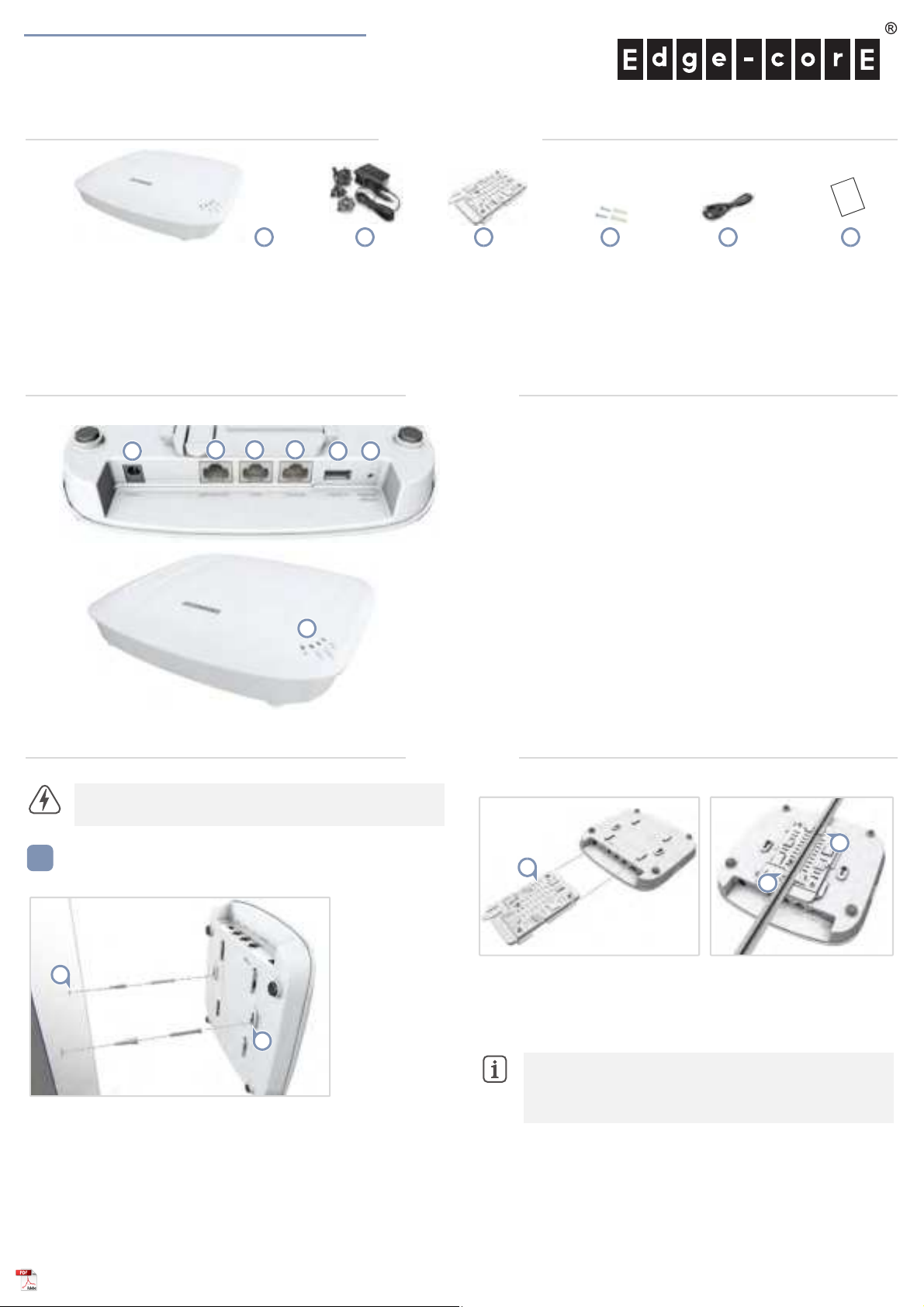
1
1
2
2
2
1
1.
12 VDC power input
2. Uplink(PoE) Port: 2.5Gbps connection to 802.3at PoE LAN device.
3. LAN Port: 2.5Gbps connection to LAN devices.
4. Console port
5. USB 2.0 port (reserved for future use)
6. Restart/Reset button:
■
A quick press restarts the system.
■
A 5 second press resets to factory defaults.
7. System LED Indicators:
■
Uplink(PoE): On (link), Blinking (traffic)
■
2.4G: On (radio on), Blinking (traffic)
■
5G: On (radio on), Blinking (traffic)
■
Status: On (power OK), Blinking (boot up)
2 3
4
516
7
Dual-Band Wi-Fi 6 Indoor Access Point
EAP102
1 2 3 4 5 6
1.
EAP102 access point
2. AC power adapter with international socket converters
3. Mounting bracket accessory
Package Contents
4. Screw kit—2 screws and 2 plugs
5. (Optional) Console cable—RJ-45 to DB-9
6. QR code card
Overview
Warning:
adapter, and all connected cables are not for outdoor use.
For indoor use only. The access point, AC power
Mount the AP
a. Mounting on a Wall
At the installation location on the wall, set two screws in the wall
1.
128 mm (5.0 in.) apart. Use the wall plugs and screws included in the
screw kit.
2. Slide the AP’s wall mounting slots down onto the screws so that the
unit is secure.
www.edge-core.com
Installation
b. Mounting on a T-Bar
1.
Slide the bracket accessory onto the base of the AP until it clicks into
its locked position.
2. Position the ceiling-mount clip holders on either side of the T-bar,
– 1 –
and then turn the AP until the two clips lock it to the T-bar.
Note:
The AP mounting supports two different sizes of
suspended ceiling T-bars. The position illustrated above is for
24.5 mm bars. Use the position at a 90 degrees angle for
15 mm bars.
E122020-CS-R01
Page 2

Quick Start Guide
2
2
1
1
3
2
1
3
4
Connect Cables
a. Connect LAN Cables
Connect Category 5e or better cable to the Uplink(PoE)
1.
RJ-45 port. When connected to a PoE source, the Uplink(PoE) port
connection provides power to the unit.
2. (Optional) Connect a local LAN switch or computer to the LAN
2.5GBASE-T RJ-45 port.
b. (Optional) Connect AC Power Adapter
2.5GBASE-T
Connect to the Web User Interface
1.
Connect a PC directly to the AP’s LAN port.
2. Set the PC IP address to be on the same subnet as the AP LAN port
default IP address. (The PC address must start 192.168.2.x with
subnet mask 255.255.255.0.)
3. Enter the AP’s default IP address of 192.168.2.1 into the web
browser address bar.
4. Log in to the web interface using default settings:
Username = admin
Password = admin
Note:
To connect to the web interface using the Uplink(PoE)
port, the IP address is automatically assigned through DHCP by
default. If a DHCP server is unreachable, the Uplink(PoE) port
reverts to a fallback IP address of 192.168.1.10.
1.
Connect the AC power adapter to the DC power jack on the AP and
then plug the adapter into a nearby AC power source.
Check AP LEDs
1. Uplink(PoE) LED — on green for a valid link.
2. 2.4G and 5G LEDs — on green for radio enabled.
3.
Power/Status LED — on green for normal operation.
Note:
To reset the AP to factory default settings, press and
hold down the AP’s Restart/Reset button for 5 seconds.
– 2 –
Page 3

Safety and Regulatory Information
FCC Class B
This equipment has been tested and found to comply with the limits for a
Class B digital device, pursuant to Part 15 of the FCC Rules. These limits
are designed to provide reasonable protection against harmful
interference in a residential installation. This equipment generates, uses
and can radiate radio frequency energy and, if not installed and used in
accordance with the instructions, may cause harmful interference to radio
communications. However, there is no guarantee that interference will
not occur in a particular installation. If this equipment does cause
harmful interference to radio or television reception, which can be
determined by turning the equipment off and on, the user is encouraged
to try to correct the interference by one of the following measures:
■
Reorient or relocate the receiving antenna
■
Increase the separation between the equipment and receiver
■
Connect the equipment into an outlet on a circuit different from
that to which the receiver is connected
■
Consult the dealer or an experienced radio/TV technician for
help
FCC Caution: Any changes or modifications not expressly approved by
the party responsible for compliance could void the user’s authority to
operate this equipment.
This device complies with Part 15 of the FCC Rules. Operation is subject
to the following two conditions: (1) This device may not cause harmful
interference, and (2) this device must accept any interference received,
including interference that may cause undesired operation.
For product available in the USA/Canada market, only channel
1~11 can be operated. Selection of other channels is not possible.
IMPORTANT NOTE:
FCC Radiation Exposure Statement:
This equipment complies with FCC radiation exposure limits set forth for
an uncontrolled environment. This equipment should be installed and
operated with minimum distance 24 cm between the radiator and your
body.
CE Statement
This equipment complies with EU radiation exposure limits set forth for an
uncontrolled environment. This equipment should be installed and
operated with minimum distance 20 cm between the radiator and your
body.
The device is restricted to indoor use only when operating in the
5150 to 5350 MHz frequency range.
All operational modes:
2.4 GHz: 802.11b, 802.11g, 802.11n (HT20), 802.11n (HT40),
802.11ac (VHT20), 802.11ac (VHT40), 802.11ax (HE20),
802.11ax (HE40)
5 GHz: 802.11a, 802.11n (HT20), 802.11n (HT40), 802.11ac
(VHT20), 802.11ac (VHT40), 802.11ac (VHT80), 802.11ax (HE20),
802.11ax (HE40), 802.11ax (HE80)
The frequency and maximum transmitted power limit in EU are listed
as below:
2412-2472 MHz: 20 dBm
5150-5350 MHz: 23 dBm
5500-5700 MHz: 30 dBm
Quick Start Guide
AT BE BG CH CY CZ
DE DK EE EL ES FI
FR HR HU IE IS IT
LI LT LU LV MT NL
NO PL PT RO SE SI
SK TR UK
The abbreviations of the countries, as prescribed in above table, where
any restrictions on putting into service or any requirements for
authorization of use exist.
CE Mark Declaration of Conformance for EMI and Safety (EEC)
This information technology equipment is in compliance with the
Directive 2014/53/EU and Directive 2014/35/EU.
The Declaration of Conformity (DoC) can be obtained from
www.edge-core.com -> support -> download.
Japan VCCI Statement
5 GHz band (W52, W53): Indoor use only
NCC Statement (Taiwan)
NCC 警語
經型式認證合格之低功率射頻電機,非經許可,公司、商號或使用者
均不得擅自變更頻率、加大功率或變更原設計之特性及功能。
低功率射頻電機之使用不得影響飛航安全及干擾合法通信;經發現有
干擾現象時,應立即停用,並改善至無干擾時方得繼續使用。
前項合法通信,指依電信法規定作業之無線電通信。
低功率射頻電機須忍受合法通信或工業、科學及醫療用電波輻射性電
機設備之干擾。
MPE
本產品電磁波曝露量 (MPE) 標準值 1mW/cm2,送測產品實測值為
0.32982mW/cm2,建議使用時至少距離人體 20cm。
Warnings and Cautionary Messages
Warning:
parts.
Warning:
out by qualified personnel only.
Warning:
connect the field ground lead on the tri-pole power plug to a
valid earth ground line to prevent electrical hazards.
Caution:
measures to prevent electrostatic discharge when handling this
equipment.
Caution:
port. This may damage this device.
Caution:
that conform to FCC standards.
This product does not contain any serviceable user
Installation and removal of the unit must be carried
When connecting this device to a power outlet,
Wear an anti-static wrist strap or take other suitable
Do not plug a phone jack connector in the RJ-45
Use only twisted-pair cables with RJ-45 connectors
– 3 –
Page 4

Hardware Specifications
AP Chassis
Size (WxDxH) 201 x 195 x 39.8 mm (7.91 x 7.68 x 1.57 in.)
Weight 0.7 kg (1.54 lb)
Quick Start Guide
Temperature Operating: 0° C to 45° C (32° F to 113° F)
Humidity Operating: 5% to 95% (non-condensing)
Network Interfaces
Ports Uplink(PoE) RJ-45 Port: 2.5GBASE -T, PoE PD
2.4 GHz Radio IEEE 802.11b/g/n/ac/ax
5 GHz Radio IEEE 802.11a/n/ac/ax
Bluetooth Radio IEEE 802.15.1
Radio Frequencies 2.4 – 2.4835 GHz (US, Canada, ETSI)
Power Specifications
PoE Input Power 24 W max, 48 VDC–55 VDC;
AC Power Adapter AC Input: 100–240 VAC, 50-60 Hz
Regulatory Compliances
Radio EN300 328 V2.2.2 (2019-07)
Storage: -40° C to 70° C (-40° F to 158° F)
LAN RJ-45 Port: 10/100/1000/2.5GBASE-T
5.15 – 5.25 GHz (lower band) US/Canada,
Europe
5.725 – 5.825 GHz (upper band) US/Canada
802.3at-compliant
DC Output: 12 VDC, 2 A
EN301 893 V2.1.1(2017-03)
47 CFR FCC Part 15.247
47 CFR FCC Part 15.407
NCC LP0002
MIC certification Rule, Article 2 Paragraph 1 Item
19
MIC certification Rule, Article 2 Paragraph 1 Item
19-3 and 19-3-2
Emissions EN 301 489-1 V2.1.1 (2017-02)
Safety Low Voltage Directive (2014/35/EU, formerly
Taiwan RoHS CNS 15663
EN 301 489-17 V3.1.1 (2017-02)
AS/NZS CISPR 32:2015, Class B
47 CFR FCC Rules and Regulations Part 15
Subpart B, Class B Digital Device
CNS 13438
MIC certification Rule, Article 9 & Article 34
2006/95/EC, formerly 73/23/EEC)
CNS 14336-1
IEC/EN 62368-1, IEC/EN 60950-1
– 4 –
 Loading...