

Eden Bath EBFM002WBN Installation Manual
Wall mounted basin mixer
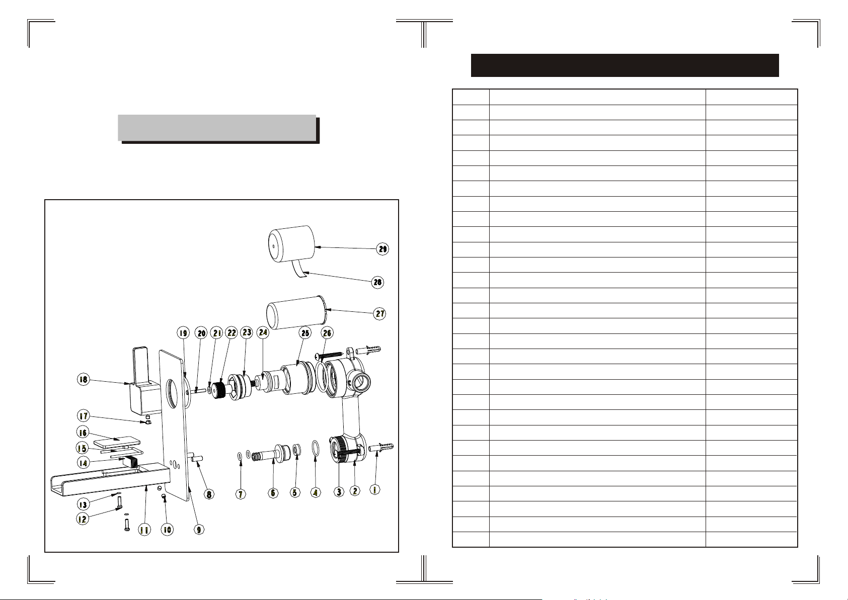
Components List
EB_FM002V
Installation Instruction
Please read this instruction carefully so as to avoid the
installation difficulty.
No
1
2
3
4
5
6
7
8
9
10
11
12
13
14
15
16
17
18
19
20
21
22
23
24
25
26
27
28
29
.
Component
Plastic sleeve
Main body
Cross-head screw
O-ring
Flow rate controller
Union
O-ring
Setting pin
Plate
Female allen screw
Spout
Cross-head screw
O-ring
Net
O-ring
Decorating cover
Plug
Handle
Sealing strip
Cross-head screw
Flat washer
Union
Cartridge fastener
Ceramic head part
Cartridge seat
O-ring
Safe cover for diverter
Index
Safe cover for cartridge
Quantity
3
1
3
1
1
1
2
2
1
3
1
2
2
1
1
1
1
1
1
1
1
1
1
1
1
1
1
1
1

Installation Step
Installation Fig
1/2-14NPT
Flow rate Curves
5
8
3
2
44
1
After installing the main body, read the index on cover , install the decorating tiles
and glue the plate (5).
9
6
7
See the fig for the position of the valve and inlet pipes.
Test:
Open the supply pipes, close the ceramic cartridge and check any leakage;
open the ceramic cartridge and check the smooth water flow. Having tested,
install the valve to the wall, take the safe cover apart and install the plate
and handle.
L/min
35
30
25
20
15
10
5
0
0.5
1.5
1
2
2.5
303.5 4
4.5 5
Test pressure:
1.6MPa (16bar)
Flow pressure:
0.05MPa
Min
1.60MPa
Max
Recommended pressure:
Bar
0.1MPa to 0.8MPa (1 to 8 bar)
Note
1.Ensure to clean the water supply pipe before installing to
avoid being jammed.
2.The cold-water supply must be connected on the right and
the hot-water supply on the left.
3.Check the installing dimension according to the Figure and
ensure it is installed correctly.
4.Hot-water inlet must not be over 80 C.
o
 Loading...