

Edelweiss EQ1-DYN User Manual
digital audio
weiss engineering ltd.
Florastrasse 42, 8610 Uster, Switzerland
) +41 1 940 20 06 2 +41 1 940 22 14
8 http://www.weiss.ch / http://www.weiss-highend.com
GAMBIT
EQ1-DYN
OPERATING MANUAL
Software Version: 0S: 1.1

OPERATING INSTRUCTIONS FOR GAMBIT EQUALIZER EQ1-DYN CONTENTS
CONTENTS
CONTENTS _______________________________________________________________________2
FRONT PANEL ____________________________________________________________________3
Front Panel Groups __________________________________________________________________________ 4
INTRODUCTION __________________________________________________________________5
Processing _________________________________________________________________________________ 5
Display____________________________________________________________________________________ 5
Snapshots _________________________________________________________________________________ 5
Remote Control_____________________________________________________________________________ 5
OPERATION ______________________________________________________________________6
Status Display_______________________________________________________________________________ 6
Band Parameters ____________________________________________________________________________ 8
Controls __________________________________________________________________________________ 9
M/S Mode ________________________________________________________________________________ 11
Snapshots ________________________________________________________________________________ 12
Dither ___________________________________________________________________________________ 14
Display Resolution __________________________________________________________________________ 14
LCD Contrast _____________________________________________________________________________ 14
EQ Bypass ________________________________________________________________________________ 14
Remote Control____________________________________________________________________________ 15
Software Information________________________________________________________________________ 15
Self Test__________________________________________________________________________________ 15
TECHNICAL DATA________________________________________________________________16
AES/EBU Input_____________________________________________________________________________ 16
AES/EBU Output ___________________________________________________________________________ 16
Power ___________________________________________________________________________________ 19
Overload _________________________________________________________________________________ 19
Filters ___________________________________________________________________________________ 19
Parameter Table ___________________________________________________________________________ 20
Dither ___________________________________________________________________________________ 22
Remote Control Protocol_____________________________________________________________________ 23
Daniel Weiss Engineering Ltd., Florastr. 42, CH-8610 Uster Page 2 of 27
) +41 1 940 20 06 2 +41 1 940 22 14 8 http://www.weiss.ch * weiss@weiss.ch
OPERATING INSTRUCTIONS FOR GAMBIT EQUALIZER EQ1-DYN FRONT PANEL
•
Ž
Œ
FRONT PANEL
•
Graph 1: Front Panel Elements
Daniel Weiss Engineering Ltd., Florastr. 42, CH-8610 Uster Page 3 of 27
) +41 1 940 20 06 2 +41 1 940 22 14 8 http://www.weiss.ch * weiss@weiss.ch

OPERATING INSTRUCTIONS FOR GAMBIT EQUALIZER EQ1-DYN FRONT PANEL
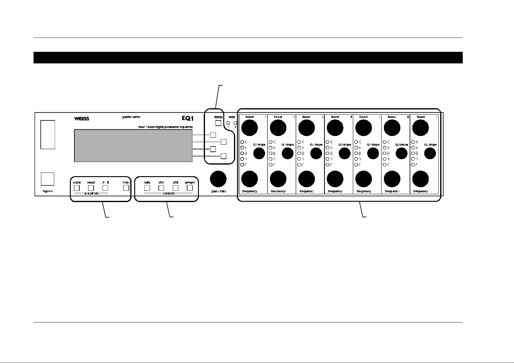
Front Panel Groups
The front panel of the EQ1 offers several control and display features. These can be grouped according to
Graph 1: Front Panel Elements:
Π- Band Parameters
• - Menu
Ž - Controls
• - Snapshots
This manual will explain how to operate the EQ1 according to these groups.
The Bypass key is discussed separately in chapter EQ Bypass (p. 14). The “gain/ data” encoder appears
throughout the rest of this manual and is therefore not explained separately.
Daniel Weiss Engineering Ltd., Florastr. 42, CH-8610 Uster Page 4 of 27
) +41 1 940 20 06 2 +41 1 940 22 14 8 http://www.weiss.ch

OPERATING INSTRUCTIONS FOR GAMBIT EQUALIZER EQ1-DYN INTRODUCTION
INTRODUCTION
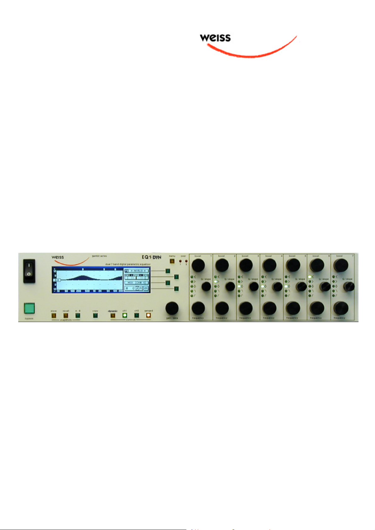
Congratulations on purchasing the Weiss Gambit Series EQ1-DYN Digital Equalizer !
The EQ1-DYN is a dynamically controlled equalizer. It has four dynamic bands and three linear
bands per channel, each operating at 88.2 or 96
kHz, depending on input sampling frequency
(88.2kHz processing with 44.1kHz and 88.2kHz
inputs, 96kHz processing with 48kHz and 96kHz
inputs).
A dynamic band operates similar to a compressor,
with two additional features:
1. The band is sensitive to signal level in its frequency range only. There is no crossmodulation from other bands. Some compressors (like the Weiss 102 Compressor)
also have this feature, called “sidechain EQ”.
The exact centre frequency and bandwidth of
the sidechain is dependent on the centre frequency and Q setting of the dynamic band.
2. The gain is only applied to certain frequencies, and not across the whole audio band.
No compressor has this feature.
In addition to the dynamic operation of the bands,
the overall dynamic frequency response is displayed in real-time in the LC display. This is necessary for the proper setup of the parameters of
the dynamic band, and it gives direct visual feedback on the operation of the EQ1-DYN, similar
to gain reduction meters on compressors.
Features of the EQ1-DYN include:
Display
Double logarithmic graph of the magnitude
function of the equalizer calculated in real
time
Status display showing sampling frequency,
channel status data handling, current workspace and snapshot number and a resetable
peak-hold and over-hold per channel
Band display (activated by touch) showing
boost, Q/ slope and frequency settings for
each band
Two over-LED’s with settable number of
consecutive over-samples which cause an
“over” display combined with an over-hold
function
Snapshots
3 x 128 non-volatile snapshots where all
parameters are stored
A-B workspaces for quick comparison be-
tween two settings
Remote Control
Supports MIDI, RS-232 and RS-422 proto-
cols
Standard MIDI Continuous Controllers for
Processing
Four dynamic peaking filters with threshold
adjustment.
24bit digital input, internal 40bit floating-
point arithmetic, dithered output for 16bit,
20bit or 24bit wordlengths.
Daniel Weiss Engineering Ltd., Florastr. 42, CH-8610 Uster Page 5 of 27
) +41 1 940 20 06 2 +41 1 940 22 14 8 http://www.weiss.ch * weiss@weiss.ch
parameter remote control (including overall
gain)
Snapshot automatization with MIDI Pro-
gram Change Commands
MIDI Dump of Snapshots
OPERATING INSTRUCTIONS FOR GAMBIT EQUALIZER EQ1-DYN OPERATION
OPERATION
The following explanations assume that the equalizer is in power-up mode, i.e. no menu is active.
If a menu is active, press the “menu” key repeatedly until the status display appears.
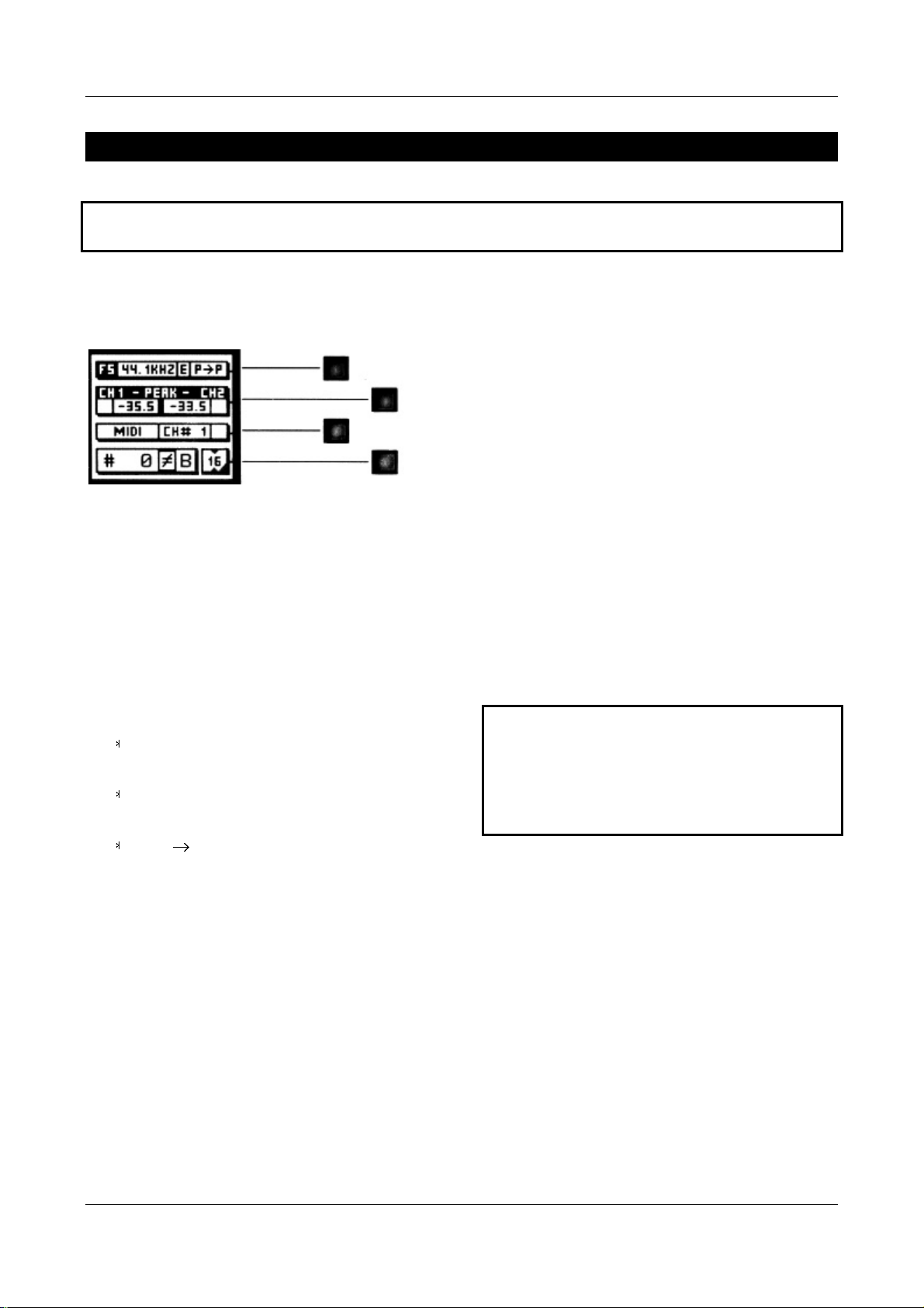
Status Display
Key A
Key B
Key C
Key C
Key D
Graph 2: Status Display
The status display consists of four groups displaying audio signal properties and information about
the current state of the EQ1. The groups are
situated adjacent to the softkeys to the right of
the LCD (Graph 2).
Channel Status Group
Situated adjacent to key A, displays the following
information:
sampling frequency in kHz: “44.1”, “ 48”,
“88.2” or “96”
pre-emphasis: “E” appears if pre-emphasis
is set (empty if not used)
input output channel status data format:
“C” for consumer and “P” for professional
To change the output channel status data format,
press key A and select format type or loop
through.
Peak Group
Use this value to set the optimal gain for a specific
session. Reset it for every session.
Over-Hold
Whenever an over is encountered, the boxes to
the side of the peak-hold values are marked.
The functions of the over-LED’s and the over-
hold both depend on the NUMBER OF
CONSECUTIVE OVER-SAMPLES setting. To adjust this
setting, press key B once. Use the “gain/ data”
encoder to change the value, then press “menu”
to return to the status display.
This setting defines the number of consecutive
over-samples needed for an over-indication. To
indicate every over-sample, enter 1. If another
value is entered, you are still able to detect a single over-sample with the peak-hold function.
Over-samples are defined as exceeding the
24bit integer range. A full scale signal
(0dBFS) will not be treated as over. A signal
that triggered an over in a previous processor in the audio chain will therefore not
trigger an over in the EQ1 (unless boosted).
Remote Group
Situated adjacent to key C, displays remote control protocol (“MIDI”, “RS 232” or “RS 422”),
channel (“1” - “16”) and status (on/ off, displayed
with check box).
Situated adjacent to key B, this group contains a
peak-hold and an over-hold for each channel. To
For remote control set-up see chapter Remote
Control.
reset these values press key B twice.
Peak-Hold
The numeric peak value is measured relative to
0dBFS, where 0dB equals digital full scale.
Daniel Weiss Engineering Ltd., Florastr. 42, CH-8610 Uster Page 6 of 27
) +41 1 940 20 06 2 +41 1 940 22 14 8 http://www.weiss.ch * weiss@weiss.ch

OPERATING INSTRUCTIONS FOR GAMBIT EQUALIZER EQ1-DYN OPERATION
Snapshot Display
Bottom line in the status display. Refer to this for
information on current workspace and snapshot.
There are two workspaces (“A” and “B”) for
quick comparison of two equalizer settings. A
workspace can be stored to a snapshot for later
use.
The number of the last recalled snapshot will be
displayed. If you change any value after the recall,
the “ ” will change to “ ” to symbolize that the
workspace is not equal to the displayed snapshot
anymore.
For snapshot handling see chapter Snapshots.
Dither Icon
The dither icon is situated right next to key D
(see Graph 2). If dither is off, the icon contains
the number “24“, the word length of the output
signal in bits. Turning dither on will produce arrows above and below the new word length
number (“16“ or “20“). Additionally, if autoblacking is enabled, the bottom right corner of the
icon is inverted.
For details on dither refer to chapter Dither.
Daniel Weiss Engineering Ltd., Florastr. 42, CH-8610 Uster Page 7 of 27
) +41 1 940 20 06 2 +41 1 940 22 14 8 http://www.weiss.ch * weiss@weiss.ch
OPERATING INSTRUCTIONS FOR GAMBIT EQUALIZER EQ1-DYN OPERATION
Band Parameters
What Is A Band?
The EQ1 has seven independent bands per channel. A band has the following parameters which
can be adjusted separately for each band:
1. Mode
2. Boost
3. Q/ Slope / Shape
4. Frequency
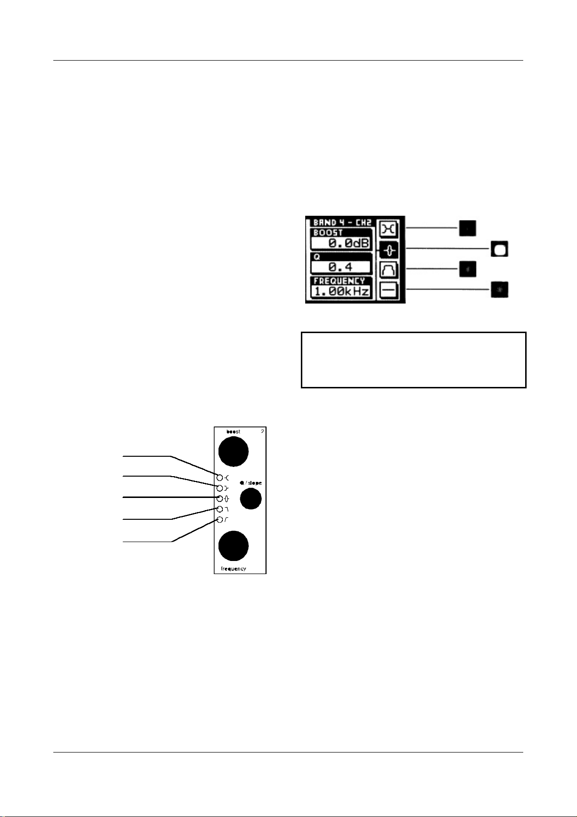
Mode specifies the filter type. There are five filter
types (low and high cut, low and high shelving and
peaking) and a bypass mode. Each band has its
own five-LED chain to indicate its active mode
(see
Graph 3).
To activate a band and see its detailed parameter
values, touch any knob in a band (see Graph 1,
Œ
). The active band’s parameter values will be
shown in the band display (see Graph 4) replacing
the status display, and its LED chain will light up,
showing you where to adjust the parameter values.
Graph 4: Band Display
Depending on the setting of “Auto Switchback From Band To Status Display”, this
display will hold or disappear again after
having released the knob.
High Shelving
Low Shelving
Peaking
High Cut
Low Cut
To change the “Auto Switchback From Band To
Status Display” setting, press the “menu” key,
then select “Controls” with key B. The value can
now be changed with key B.
Range
The parameters’ range is independent of the
mode and is listed at page 20.
Graph 3: Mode LEDs
Daniel Weiss Engineering Ltd., Florastr. 42, CH-8610 Uster Page 8 of 27
) +41 1 940 20 06 2 +41 1 940 22 14 8 http://www.weiss.ch * weiss@weiss.ch
OPERATING INSTRUCTIONS FOR GAMBIT EQUALIZER EQ1-DYN OPERATION
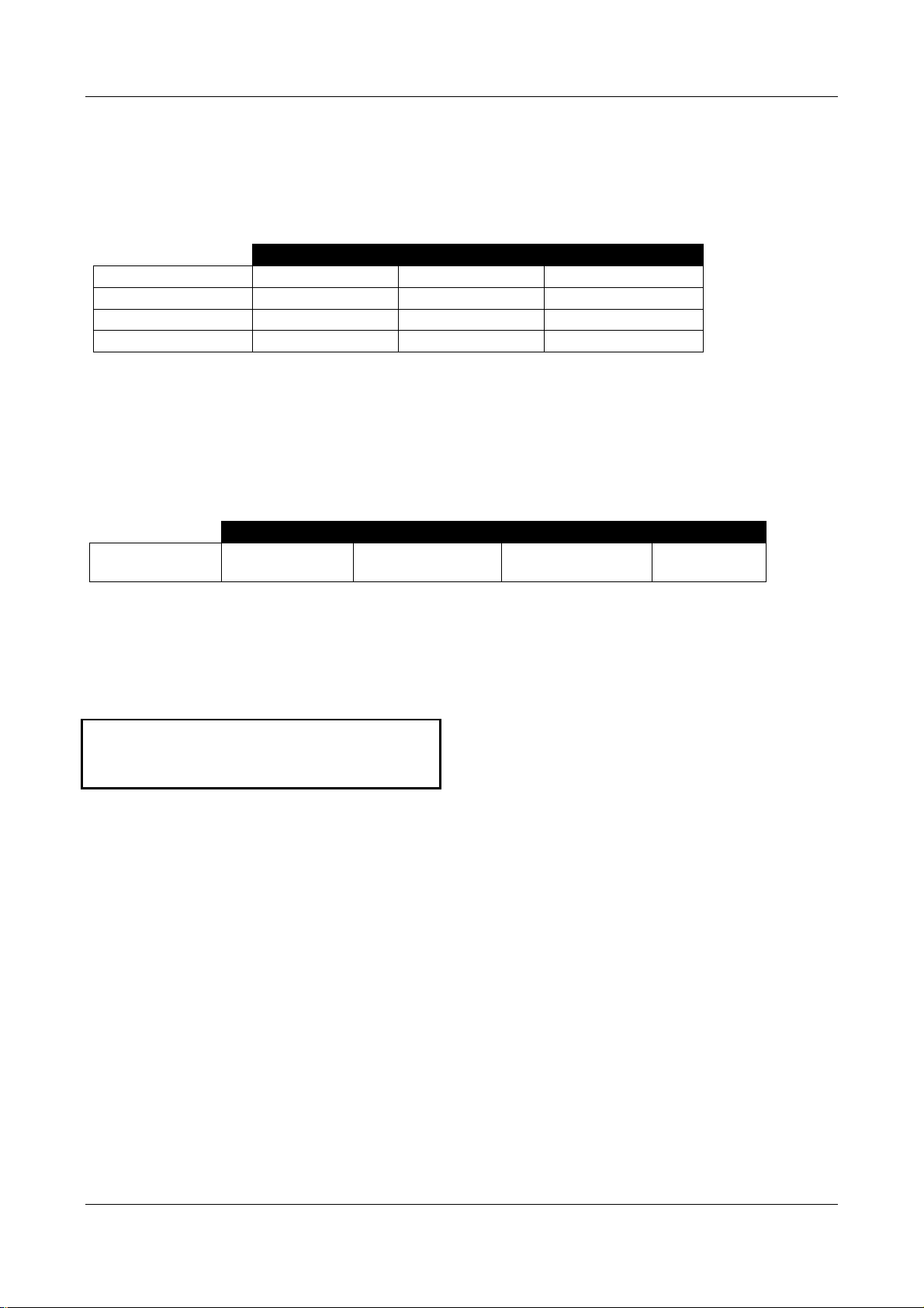
Adjusting Band Parameters
To adjust boost, Q/ slope or frequency simply
turn the corresponding knob (see Table 1).
“boost” “Q/ slope” “frequency”
Peaking-Filter
Dynamic-Peaking
Shelve-Filter
Cut-Filter
set boost set Q set centre frequency
set boost set Q / threshold set centre frequency
set boost set shape set 3dB frequency
- set slope set -3dB frequency
To adjust the mode, activate the band. Press a
key (Table 2) to change the mode value. The active mode is highlighted and the adjacent softkey
is lit.
Key A Key B Key C Key D
Mode
toggle lo- / hishelve
toggle peaking
/dynamic peaking
Controls
See Graph 1: Front Panel Elements, Ž.
Table 1
CH1 & CH2
These two keys patch the band controls to the
according channels. The band controls can either
be separate for each channel or ganged together.
toggle lo- / hi-cut bypass
If the band bypass is on (highlighted), its filter
settings (type and parameters) are saved but have
no effect on the audio signal. Turning bypass off
will restore the previous band settings.
Bypassing all bands is sonically equivalent to
using the overall bypass (refer to EQ Bypass)
if the gain is set to 0.0dB.
Only bands 1, 2, 5, and 6 can be set into dynamic
mode. This allows for linear gain adjustment before and after a dynamic band.
Table 2
The key is lit for the active channel.
To copy CH1 settings to CH2 or vice versa, press
the “copy” key and select an option (Graph 6).
Ganged
When this key is lit, the band controls act for both
channels simultaneously. Switching channels while
the “ganged” key is lit will activate CH1 and CH2
settings alternately for both channels.
If ganged is off, the controls will affect the active
channel only.
Daniel Weiss Engineering Ltd., Florastr. 42, CH-8610 Uster Page 9 of 27
) +41 1 940 20 06 2 +41 1 940 22 14 8 http://www.weiss.ch * weiss@weiss.ch
 Loading...