

Edelweiss DS1-MK3 User Manual
digital audio
weiss engineering ltd.
Florastrasse 42, 8610 Uster, Switzerland
+41 44 940 20 06 +41 44 940 22 14
http://www.weiss.ch / http://www.weiss-highend.com
GAMBIT
DS1-MK3
OPERATING MANUAL
Software Version: 0S: 3.0, DSP: 3.0
Release Date: May, 2008

digital audio
weiss engineering ltd.
Florastrasse 42, 8610 Uster, Switzerland
+41 44 940 20 06 +41 44 940 22 14
http://www.weiss.ch / http://www.weiss-highend.com
Authors: Andor Bariska, Daniel Weiss, Weiss Engineering LTD.
Weiss Engineering LTD. reserves the right to make changes to product specification or documentation without prior notice. Updated manuals and datasheets
are available at our website for downloading. Weiss Engineering LTD. makes no
warranty, representation or guarantee regarding the suitability of its products
for any particular purpose, nor does part of this manual, and specifically discalims any and all liability, including without limitation consequential or incidental
damages.
All rights reserved. No part of this publication may be reproduced or transmitted in any form or by any means, electronic or mechanical including photocopying, scanning or any information storage or retrieval system without the express prior written consent of the publisher.
© Copyright Weiss Engineering LTD., 2008.
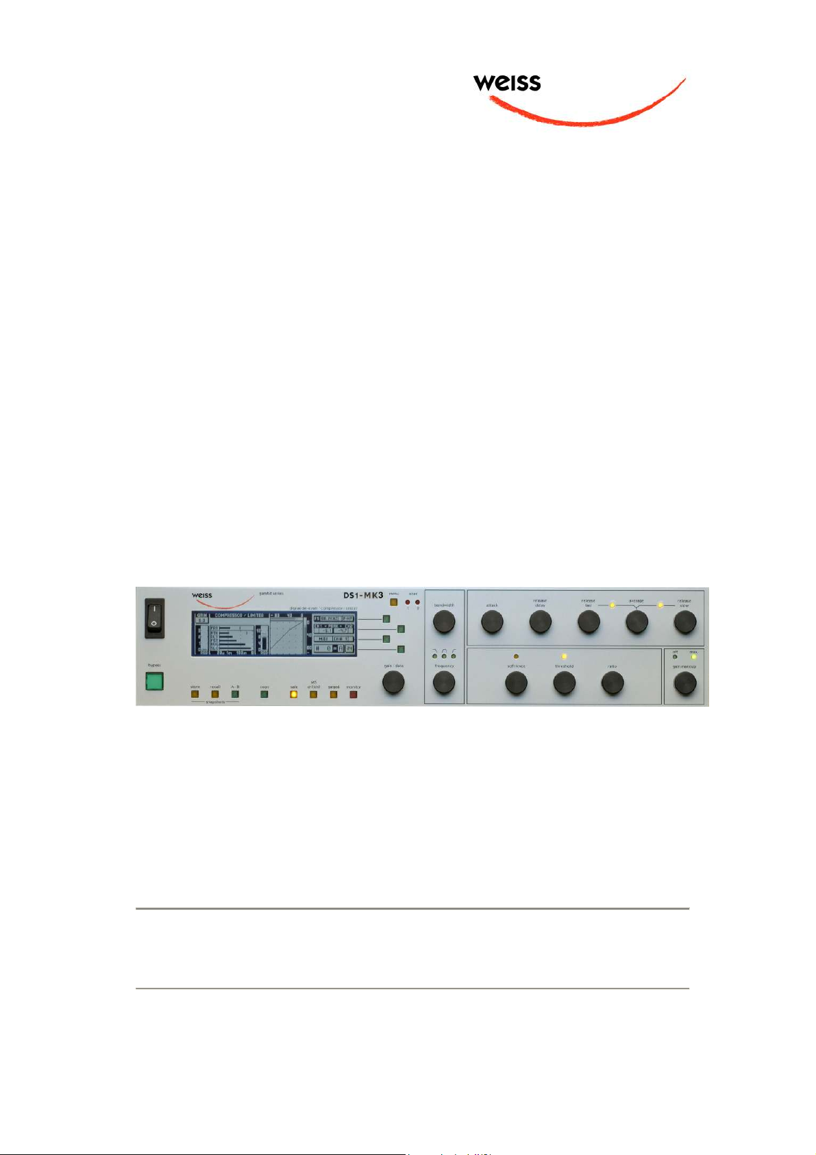
OPERATING INSTRUCTIONS FOR GAMBIT DE-ESSER/COMPRESSOR DS1-MK3 FRONT PANEL
dig ital de -esser / c ompre ssor / lim iter
FRONT PANEL
menu
gamb it seri es
byp ass
cop yA - Brec allsto re
sna pshots
Graphic 1: Front Panel Elements
saf e
M/S
ch1/ ch2
DS1-M K3
moni tor
gan ged
menu
gai n / data
over
ove r
1 2
1 2
band widt h
att ack
rel ease
del ay
gai n makeupfre quency
rel ease
slo w
max.off
rel ease
fas t
thr eshol d rat iosof t-knee
ave rage
Graphic 2: Display Elements
Weiss Engineering Ltd., Florastr. 42, CH-8610 Uster Page 3
+41 44 940 20 06 +41 44 940 22 14 http://www.weiss.ch weiss@weiss.ch

OPERATING INSTRUCTIONS FOR GAMBIT DE-ESSER/COMPRESSOR DS1-MK3 FRONT PANEL
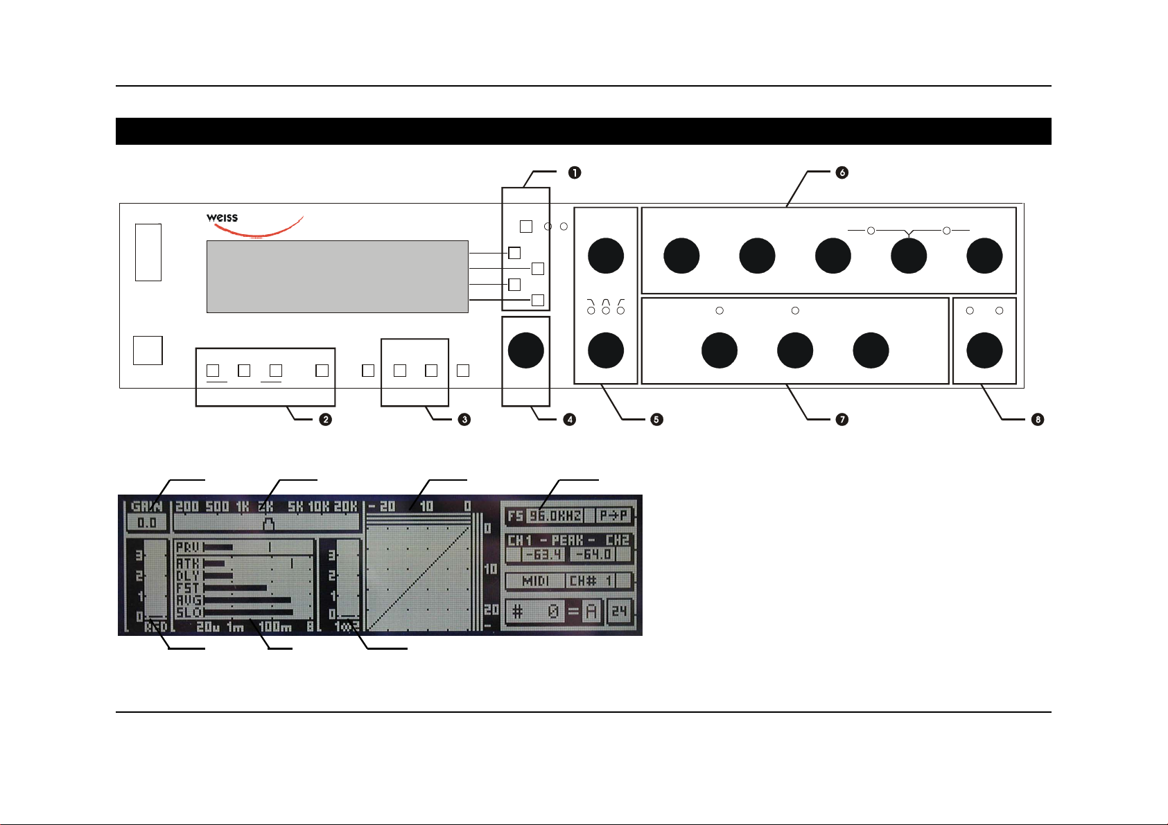
Front Panel Groups
The front panel of the DS1-MK3 offers several control and display features.
Control
Refer to Graphic 1: Front Panel Elements
- Menu- and softkeys p. 7
- Snapshot keys p. 19
- ganged / channel select keys p. 16
- Gain / Data controller p. 8
- Crossover controllers p. 12
- Envelope follower controllers p. 10
+
Display
Refer to Graphic 2: Display Elements
- Non-linear transfer curve controllers p. 11
- Gain value p. 8
- Crossover setting (frequency selective mode only) p. 12
- Non-linear transfer curve and signal metering p. 11
- Status display p. 7
- Peak limiter gain reduction meter p. 8
- Envelope follower settings p. 10
- Compressor gain reduction meters p. 10
Weiss Engineering Ltd., Florastr. 42, CH-8610 Uster Page 4
+41 44 940 20 06 +41 44 940 22 14 http://www.weiss.ch weiss@weiss.ch

OPERATING INSTRUCTIONS FOR GAMBIT DE-ESSER/COMPRESSOR DS1-MK3 INTRODUCTION
INTRODUCTION
Congratulations on purchasing the Weiss DS1-MK3 De-esser / Compressor !
This two channel digital De-esser / Compressor
features linear-phase crossover filters covering
the whole audio band. Thus the DS1-MK3 is not
just a De-esser but can also be used as band
selective or full band Compressor / Limiter. The
controls for the two channels can be ganged or
unganged (useful for M/S compression). Similarly, sidechain linking can be turned off.
Internal processing is either 88.2kHz (with 44.1
and 88.2kHz input) or 96kHz (with 48 or 96kHz
input) in DeEsser and in Compressor mode.
Double-precision up- and down-sampling units
within the DS1-MK3 result in negligible distortion and high transparency for absolutely clean
sound.
The non-linear segment can be adjusted from
1000:1 to 1:5, allowing every kind of dynamic
processing, from limiting to upward expansion
(for over-compressed signals). Put back a little
dynamics into that ultra-finalized mix!
An additional safety-limiter takes care of any
overs that are generated in DeEsser as well as in
Compressor mode.
This and the ability to remote control parameters and snapshots makes the DS1-MK3 the
perfect tool for the recording and mastering
engineer!
Processing
∗ 24bit digital input, internal 40bit floating-
point arithmetic, dithered output for 16bit,
20bit or 24bit wordlengths.
∗ Transparent phase-linear crossover for
frequency selective compression
∗ All parameters are immediately accessible
with instant feedback through LEDs and
the LC display.
∗ Logarithmic graph of the transfer function
of the de-esser/compressor calculated in
real time
∗ Status display showing sampling fre-
quency, channel status data handling, current workspace and snapshot number and
a resetable peak-hold and over-hold per
channel
∗ Parameter display (activated by touching
the knobs) showing all timing, level and
gain parameters
∗ Signal status LEDs, showing OVERs, range
of envelope signal and the status of the
release time comparator
Snapshots
∗ 3 x 128 non-volatile snapshots where all
parameters are stored
∗ A-B workspaces for quick comparison be-
tween two settings
Remote Control
∗ Supports MIDI, RS-232 and RS-422 proto-
cols
∗ Standard MIDI Continuous Controllers for
parameter remote control (including overall gain)
∗ Snapshot automatization with MIDI Pro-
gram Change Commands
∗
MIDI Dump of Snapshots
Display
∗ Standardised peak meters for compressor-
stage in- and output with peak hold
∗ Gain reduction meter with peak hold for
compressor and for safety-limiter each.
Weiss Engineering Ltd., Florastr. 42, CH-8610 Uster Page 5
+41 44 940 20 06 +41 44 940 22 14 http://www.weiss.ch weiss@weiss.ch

OPERATING INSTRUCTIONS FOR GAMBIT DE-ESSER/COMPRESSOR DS1-MK3 UPDATE
HISTORY
UPDATE HISTORY
(for example) high frequency inner details at low
Update from DS1 to DS1MK2 v1.0 or v1.1
The main difference between these two versions
is the ability of the DS1-MK2 to accept 88.2 /
96kHz input signals. Contrary to the DS1, where
double sampling processing was only used in
compressor mode, the DS1-MK2 now uses internal up- and downsampling stages and all processing is at 88.2 / 96 kHz.
There is a completely new feature available in
the DS1-MK2, the upward expander. This is the
logical extension of the compressor. Just turn
the ratio controller counterclock wise to experience this new sound. New scale range on p. 26.
The DeEsser section has been enhanced with a
new crossover, which covers the whole audio
bandwidth (the DS1 used 271 Hz as lowest cutoff frequency, the DS1-MK2 can now be tuned
down to 41 Hz). New scale range on p. 25.
And for those who like it hot, there is a new
peak limiter section added in series to the compressor / de-esser, which cuts down spikes
above 0.0dBFS. Read about its operation on p.8.
Update from DS1-MK2
v1.0 or v1.1 to DS1-MK2
v1.3
The main new enhancement is the parallel compressor option. To read about operating and
options of the parallel compressor, turn to p. 14.
This way of using a compressor was motivated
by Bob Katz, here is what he says about it on
the Mastering Webboard:
“You want a patch that compresses without
stomping on the attacks at all, preserves transients but gives you great inner detail? ...
You have one control, one control only, and that
is the output level of the compressor [gain
makeup], the ‘sidechain’. You can bring out inner details without losing breathing, and hardly
affecting the upper dynamics at all. Works great.
Not just great, absolutely fantastically. Fattens
bass instruments without causing breathing or
pumping. You name it, it works very well.
Variations: Use it like the Dolby Spectral Enhancer, by split band [parallel] compression, so that
levels are enhanced. ”
The other change in architecture is the addition
of a second gain before the safety limiter, referred to as pre-limiter gain. The old overall gain
is also still available. Read on p. 8.
Also, the scales of the gain, gain makeup and
ratio parameters has been modified to suit customer feedback. New values on p. 26.
Update from DS1-MK2
v1.3 to DS1-MK2 v2.0
In the v2.0 version POW-R dithering capabilities
have been added. The dithering menu now has a
"setup" entry which gives you access to the
three POW-R algorithms.
Update from DS1-MK2
v2.0 to DS1-MK2 v2.1
New Feature: Safety Limiter is now also of auto
release type. No changes to the user interface.
Update from DS1-MK2
v2.x to DS1-MK3 (v3.0)
After several years of the DS1’s use in mastering
and recording studios world wide we have gathered and implemented a list of most wanted
features suggested by our customers.
These include:
- Ganged or unganged control, i.e. independent
parameters in L/R or M/S possible
- M/S or L/R processing
- Switchable sidechain link
- Continuously variable signal sensing from Peak
to 800ms RMS
Weiss Engineering Ltd., Florastr. 42, CH-8610 Uster Page 6
+41 44 940 20 06 +41 44 940 22 14 http://www.weiss.ch weiss@weiss.ch
OPERATING INSTRUCTIONS FOR GAMBIT DE-ESSER/COMPRESSOR DS1-MK3 OPERATION
OPERATION
The following explanations assume that the de-esser/compressor is in power-up mode, i.e. no
menu is active. If a menu is active, press the “menu” key repeatedly until the status display
appears.
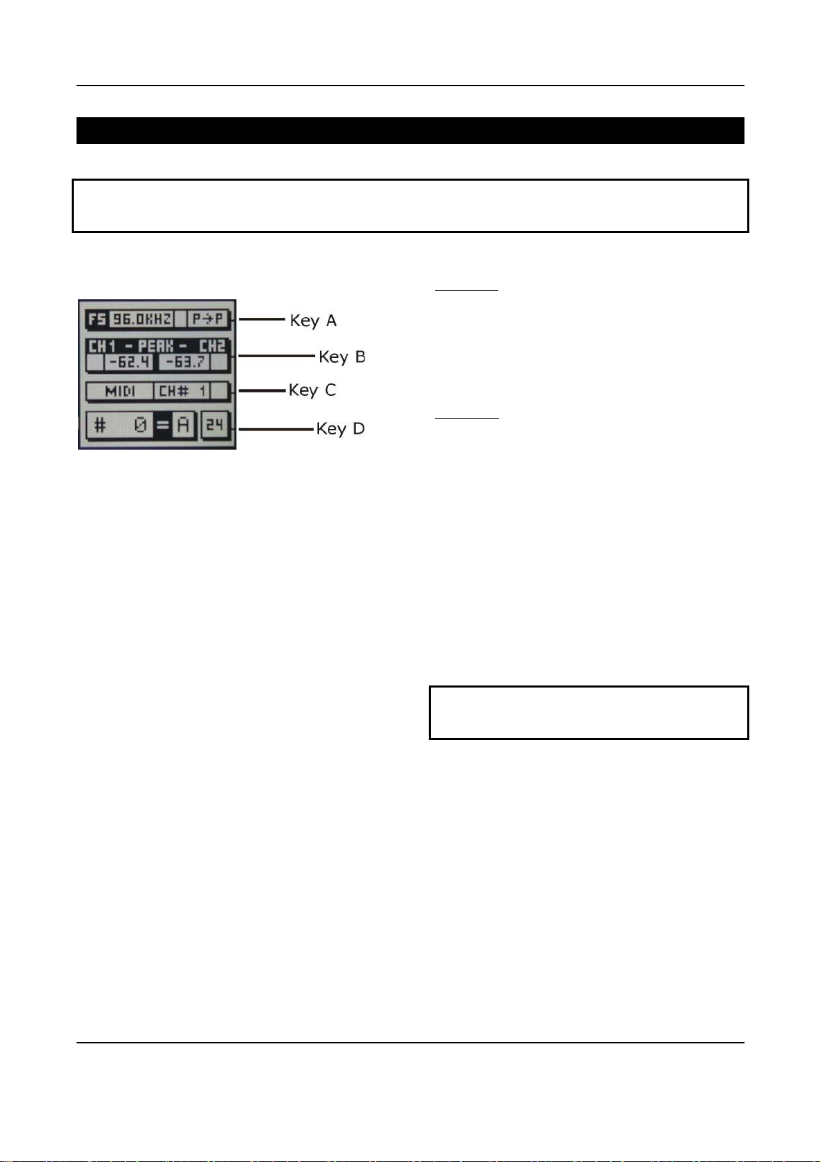
Status Display
Graphic 3: Status Display
The status display consists of four groups
displaying audio signal properties and
information about the current state of the DS1MK3.
Channel Status Group (Key A)
Situated adjacent to key A, displays the following information:
∗ sampling frequency in kHz: “44.1”, “48”,
“88.2” or “96”.
∗ pre-emphasis: “E” appears if pre-
emphasis is set (empty if not used)
∗ input → output channel status data for-
mat: “C” for consumer and “P” for professional
To change the output channel status data format, press key A and select format type or loop
through.
Peak Group (Key B)
Situated adjacent to key B, this group contains a
peak-hold and an over-hold for each channel. To
reset these values press key B twice.
Peak-Hold
The numeric peak value is measured relative to
0dBFS (digital full scale).
Use this value to set the optimum gain for a
specific session. Reset it for every session by
pressing key B twice.
Over-Hold
Whenever an over is encountered, the boxes to
the side of the peak-hold values are marked.
The functions of the over-LED’s and the overhold both depend on the NUMBER OF
CONSECUTIVE OVER-SAMPLES setting. To adjust
this setting, press key B once. Use the gain/
data controller () to change the value, then
press “menu” to return to the status display.
This setting defines the number of consecutive
over-samples needed for an over-indication. To
indicate every over-sample, enter 1. If another
value is entered, you are still able to detect a
single over-sample with the peak-hold function.
Over-samples are defined as exceeding the
integer range. A full scale signal (0dBFS)
will not be treated as over.
Remote Group (Key C)
Situated adjacent to key C, displays remote
control protocol (“MIDI”, “RS 232” or “RS 422”),
channel (“1” - “16”) and status (on/ off, displayed with check box).
For setup see chapter Remote Control (p.21).
Weiss Engineering Ltd., Florastr. 42, CH-8610 Uster Page 7
+41 44 940 20 06 +41 44 940 22 14 http://www.weiss.ch weiss@weiss.ch
OPERATING INSTRUCTIONS FOR GAMBIT DE-ESSER/COMPRESSOR DS1-MK3 OPERATION
Out-
Output
Snapshot Display (Key D)
Bottom line in the status display. Refer to this
for information on current workspace and snapshot. There are two workspaces (“A” and “B”) for
quick comparison of two de-esser/compressor
settings. A workspace can be stored to a snapshot for later use.
The number of the last recalled snapshot will be
displayed. If you change any value after the
recall, the “=” will change to “≠” to symbolise
that the workspace is not equal to the displayed
snapshot anymore.
For snapshot handling see chapter Snapshots
(p.19).
Dither Icon (Key D)
The dither icon is situated right next to key D
(see Graphic 3). If dither is off, the icon contains
the number “24“, the word length of the output
signal in bits. Turning dither on will produce
arrows above and below the new word length
number (“16“ or “20“). Additionally, if autoblacking is enabled, the bottom right corner of
the icon is inverted.
For details on dither refer to chapter Dither (p.
18).
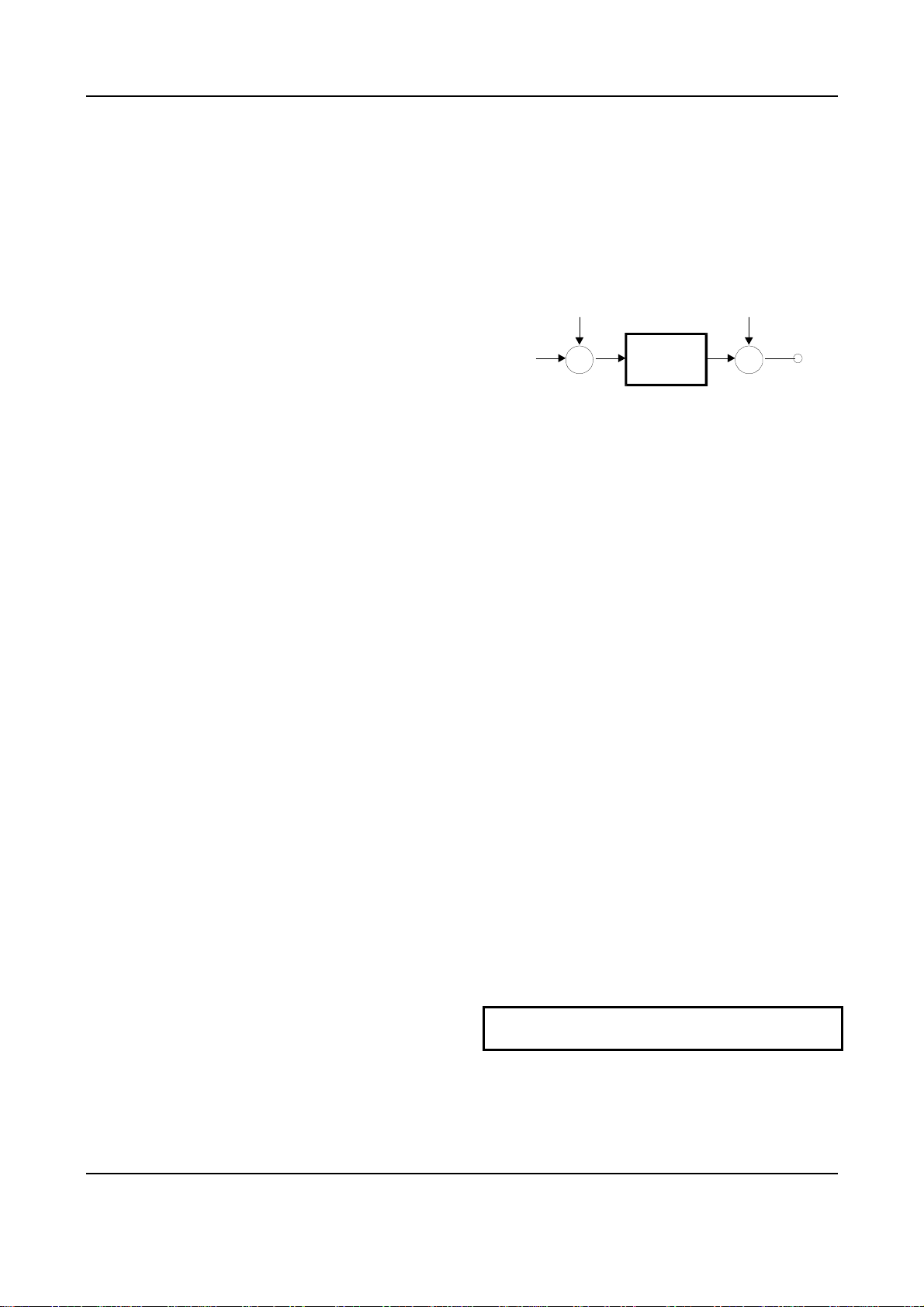
Gain / Output Gain
There are two gains, one pre safety-limiter and
one post safety-limiter, as depicted in Graphic 4.
Gain
from previous
processing
Graphic 4: Output section
When touching the gain controller (), the
required gain can be selected from a menu. To
change the output gain, press softkey D. If an
arrow appears inside the output gain window,
the Output Gain can be adjusted. Press the D
key again to control the pre-limiter gain which is
shown in the upper left corner of the display.
Both gains are bypassed when Bypass is active.
The value shown in is the setting of the prelimiter gain.
The post-limiter output gain should be used to
set the maximum output level only (usually
0.0dB).
X X
Safety
Limiter
Gain
put
Safety Limiter
This feature is activated by pressing the “safe”
key. When the “safe” key is lit, the limiter is on.
Safety limiter activity can be monitored with the
second gain reduction meter below the “GAIN”
window ().
If the “safe” key is lit, overs will be limited by
this fast peak limiter. The parameters of the
limiter are fixed and cannot be adjusted.
However, the pre-limiter gain can be used to
drive the safety limiter.
Too much pre-limiter gain will result in distortion!
Weiss Engineering Ltd., Florastr. 42, CH-8610 Uster Page 8
+41 44 940 20 06 +41 44 940 22 14 http://www.weiss.ch weiss@weiss.ch
OPERATING INSTRUCTIONS FOR GAMBIT DE-ESSER/COMPRESSOR DS1-MK3 OPERATION
Non-Linear
Transfer Curve
x
Sidechain
Mainchain
Out-
Compressor Parameters
Following is a detailed description of all parameters that can be adjusted in the compressor stage. Guidelines are given for settings (see also the factory presets), but optimal settings are usually programme
dependent, so experimenting and listening is inevitable for satisfying results.
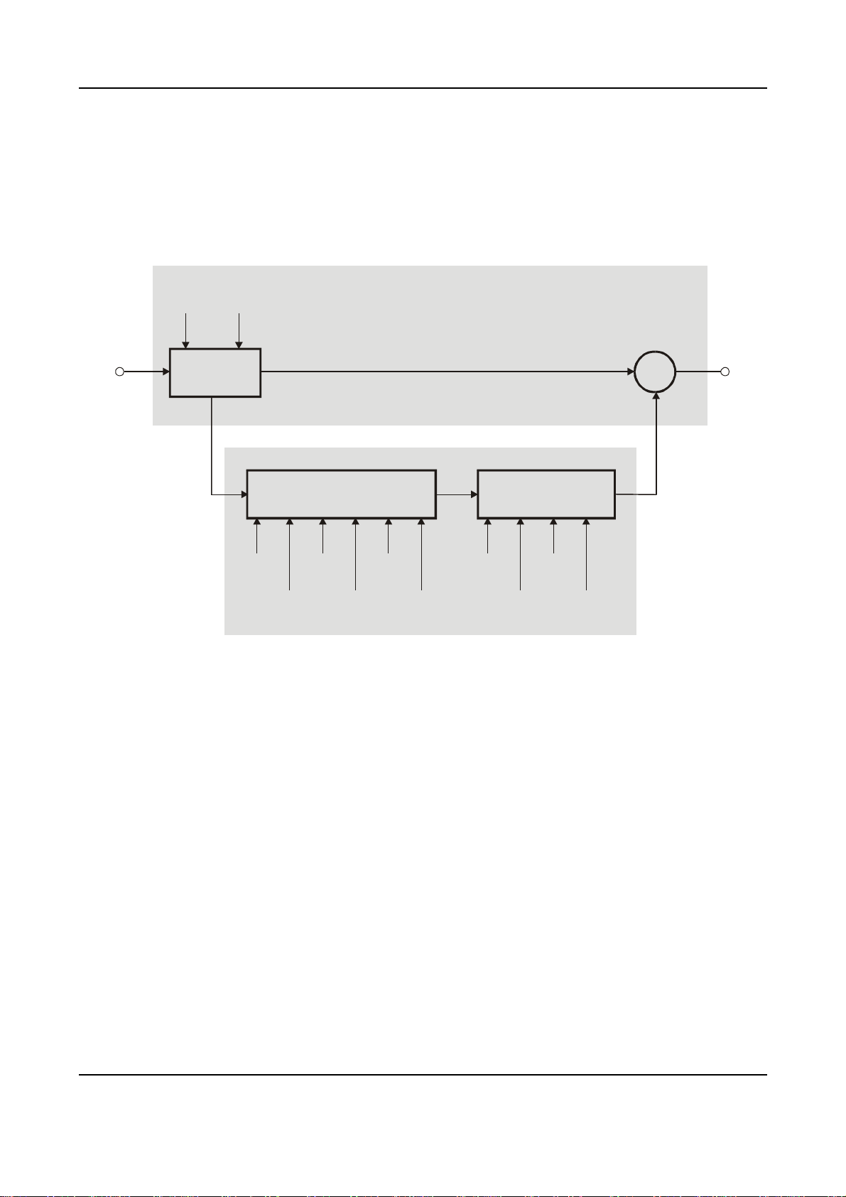
Graphic 5 shows schematic and parameters of the DS1-MK3 compressor stage:
overall
delay
preview
Input
Graphic 5: Compressor schematic
Delay
Envelope
Detection
attack
release
delay
release
fast
average RMS
release
slow
soft-knee
threshold
audio signal
put
gain control
signal
ratio
gain
makeup
Delay
A typical compressor/limiter circuit measures
the audio signal and then generates the gain
reduction control signal. At the time the control
signal changes the gain, the programme material is already there, so the gain change occurs
too late. The result is overshoot and possible
subsequent distortion.
The DS1-MK3 uses a different method to generate the gain control signal: The audio passing
through the mainchain is delayed by a fixed
amount of time, determined by the „overall delay“. By branching the signal out of the delay
line, the sidechain „sees“ the signal before it
reaches the output, thus allowing look-ahead
compared to the mainchain. The resulting corrected output signal has no overshoots, no leading edge distortion or other side effects due to
timing lags in the sidechain.
Weiss Engineering Ltd., Florastr. 42, CH-8610 Uster Page 9
The preview (the time the signal reaches the
sidechain ahead of the multiplier) cannot, of
course, exceed the overall delay.
The overall delay is the sum of the maximum
overall delay („Delay“ box in Graphic 5) and the
delay required for other signal processing (linear-phase filtering for up- and downsamplers).
Any snapshot value of the preview delay which
exceeds this maximum, is clipped to the maximum, because the overall delay is not stored in
the snapshots and therefore the preview delay in
any snapshot can exceed the currently selected
overall delay.
Setting overall delay: The overall delay is
adjusted by pressing the „menu“ key () then
selecting the „system“ and then the „overall
delay“ option. Use the gain / data controller
() to change the delay value. Maximum consequential preview time and delay in frames is
also displayed. Please note that during delay
+41 44 940 20 06 +41 44 940 22 14 http://www.weiss.ch weiss@weiss.ch
OPERATING INSTRUCTIONS FOR GAMBIT DE-ESSER/COMPRESSOR DS1-MK3 OPERATION
change, audio is muted to avoid audio signal
cuts.
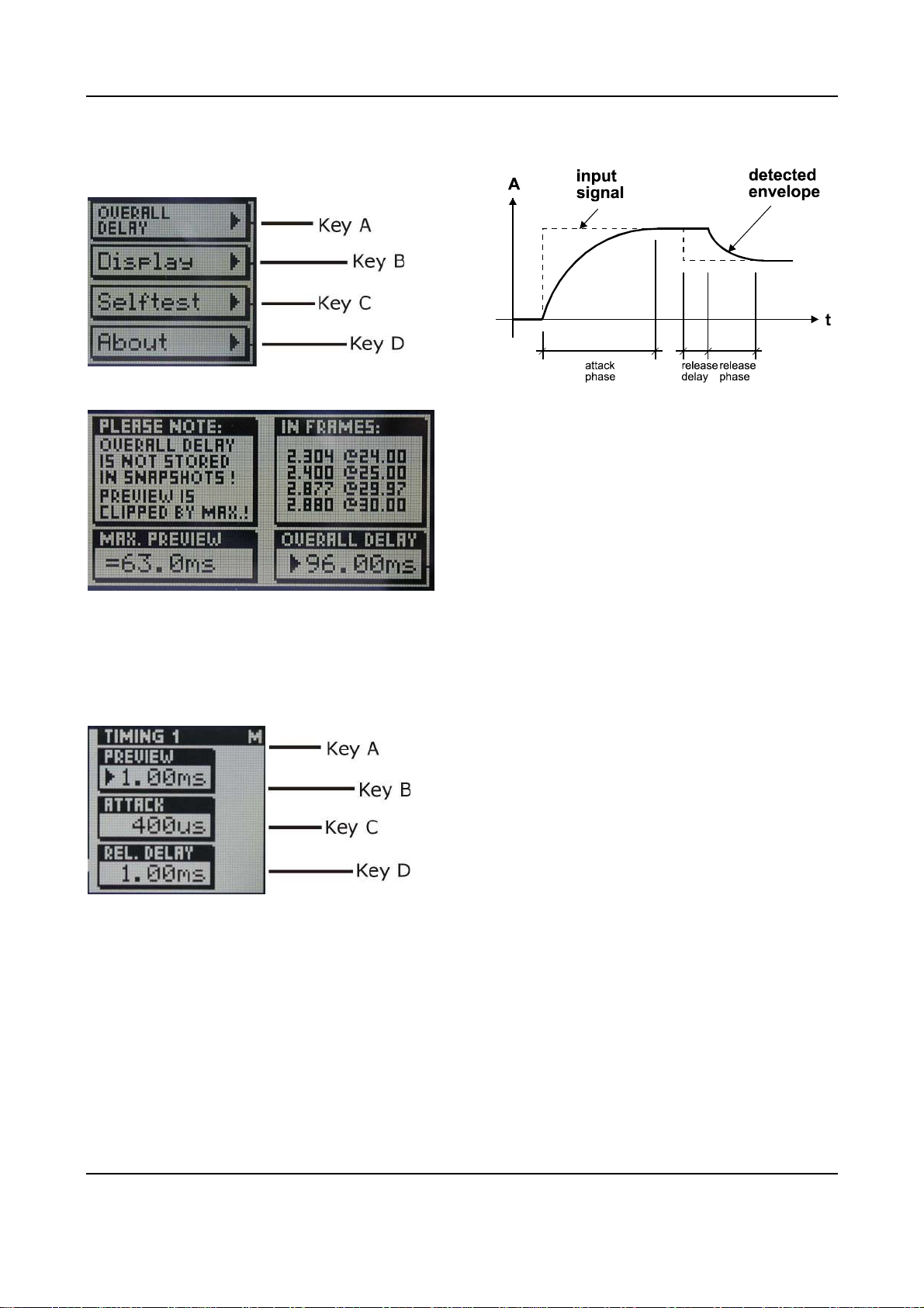
Graphic 6: System menu
Graphic 9: Envelope Parameters
Attack and Preview: The longer the attack
time, the more will the leading edge of fast transients pass by the gain reduction circuit unaltered (as in Graphic 9 during attack phase).
Very fast attack time settings such as 20µs, i.e.
one sample period, do catch every transient, but
may distort low frequencies. To utilise longer
attack times and still catch fast transients, use
preview.
Release and Average: The input signal is
monitored with two different methods: peak
amplitude (*) and RMS value. The peak amplitude is the programme portion we don't perceive
as very loud, however which can easily cause
overloads. The RMS value of the programme
material we perceive as loudness. Its variations
contribute most to the dynamic range of the
audio.
The sidechain processor compares the two
measurements it obtained from the peaks and
the RMS. The ratio between the two determines
which time constant would be the appropriate
release, e.g. after short duration peak the faster
release will be applied during the release phase.
The time period over which the RMS value of the
programme material is averaged is set by the
"average" parameter. The effect of the average
parameter can best be studied on the gain re-
duction meter (). Fast "average" settings will
cause most of the gain reduction meter to move
very fast (depending on the "release fast" setting) , slower settings will just have the top part
of the gain reduction move fast, with the bottom
part depending on the "release slow" setting.
(*) Peak / RMS: In the DS1-MK3 the peak
measurement is supplemented with an RMS
measurement with variable averaging time. To
access the RMS detection timeconstant touch
Graphic 7: Overall Delay display
Setting preview: Touch either the „attack“ or
„release delay“ controller () to activate the
timing 1 window, then use the gain / data con-
troller () to adjust preview time.
Graphic 8: Timing 1 window
Envelope Follower
The envelope follower parameter controllers are
in area . The purpose of the envelope follower
is to cause gradual gain changes, thus eliminat-
ing distortion. The current values are shown in
.
Weiss Engineering Ltd., Florastr. 42, CH-8610 Uster Page 10
+41 44 940 20 06 +41 44 940 22 14 http://www.weiss.ch weiss@weiss.ch
OPERATING INSTRUCTIONS FOR GAMBIT DE-ESSER/COMPRESSOR DS1-MK3 OPERATION
the gain / data controller (
window:
) which opens this
Graphic 10: Gain / Data Knob menu
Hit Key B to assign the gain / data knob to the
RMS detection timeconstant. The left endstop of
this parameter switches the detection to peak
mode, as used in all previous DS1 versions.
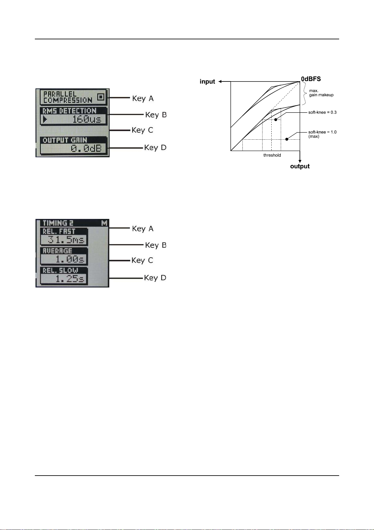
Graphic 11: Timing 2 window
Release Delay: Normally the release phase
begins immediately after the programme material has fallen in level. The release delay determines how long the DS1-MK3 holds the current
level before entering release (see Graphic 9).
The resulting dynamic characteristic is very
smooth and avoids otherwise typical 'pumping'
effects. The ideal setting is programme dependent and experimentation may be necessary to
achieve the best combination of all dynamic
parameters.
Non-Linear Transfer Curve
The transfer curve parameter controllers are in
area
+
sponsible for the actual gain reduction () calculations. The detected signal envelope is com-
pared with the transfer curve, the gain control
signal (see Graphic 5) is then adjusted accordingly if the envelope overshoots the transfer
curve.
. This part of the sidechain is re-
Graphic 12: Transfer Curve Parameters
Threshold: Sets the level which the envelope
signal has to reach before gain reduction is applied.
Ratio: Sets the slope of the segment above the
threshold. The ratio can be adjusted for compression or expansion, depending on the requirement. For full band expansion (e.g. to reintroduce dynamics into an over-compressed
signal), one will usually work with the gain
makeup set to maximum. This means that a
0.0dB input will be passed through without gain,
signals below the threshold will be reduced with
a constant gain (depending on threshold and
ratio setting, can be read from the display when
touching the gain makeup controller), and
signals between the threshold and 0.0dBFS get
expanded. For full band expansion, one will
typically have quite high thresholds (-1dB ... –
4dB), because of the resulting overall gain.
The expander can also be used in frequency
selective mode, for example to repair the effect
of a misused multi-band compressor – for this
purpose, the gain makeup can be set higher
than the calculated maximum setting, to
compensate for the overall gain that the
expander causes. This can potentially cause
overs (for loud signals in the expanded band), it
is therefore good practice to engage the safety
limiter (see below).
Weiss Engineering Ltd., Florastr. 42, CH-8610 Uster Page 11
+41 44 940 20 06 +41 44 940 22 14 http://www.weiss.ch weiss@weiss.ch
 Loading...